EP1167246B1 - Rampe hélicoidale à entrée double et à double hélice - Google Patents
Rampe hélicoidale à entrée double et à double hélice Download PDFInfo
- Publication number
- EP1167246B1 EP1167246B1 EP01114224A EP01114224A EP1167246B1 EP 1167246 B1 EP1167246 B1 EP 1167246B1 EP 01114224 A EP01114224 A EP 01114224A EP 01114224 A EP01114224 A EP 01114224A EP 1167246 B1 EP1167246 B1 EP 1167246B1
- Authority
- EP
- European Patent Office
- Prior art keywords
- chutes
- chute
- port
- pair
- items
- Prior art date
- Legal status (The legal status is an assumption and is not a legal conclusion. Google has not performed a legal analysis and makes no representation as to the accuracy of the status listed.)
- Expired - Lifetime
Links
Images

Classifications
-
- B—PERFORMING OPERATIONS; TRANSPORTING
- B65—CONVEYING; PACKING; STORING; HANDLING THIN OR FILAMENTARY MATERIAL
- B65G—TRANSPORT OR STORAGE DEVICES, e.g. CONVEYORS FOR LOADING OR TIPPING, SHOP CONVEYOR SYSTEMS OR PNEUMATIC TUBE CONVEYORS
- B65G11/00—Chutes
- B65G11/06—Chutes of helical or spiral form
- B65G11/063—Chutes of helical or spiral form for articles
Definitions
- This invention relates generally to material handling apparatus and more particularly to a spiral chute for translating items from one level to another.
- Declining chutes in the form of spirals is a component that is widely used in the material handling industry for conveying items from higher to lower elevations.
- Chutes are known to be fabricated from a variety of materials, including wood, metal, or plastics. In all cases, the chute is designed so that the items being handled will slide along a continuous conveying surface.
- Spiral chutes are generally known and are called spiral chutes because their edges and side walls form the shape of a spiral. Spiral chutes are specified by their degree of rotation, direction, width and inside radius. The degree of rotation, moreover, can be as large or as small as the particular application requires.
- One such application comprises a system for air express parcel delivery.
- parcels are consolidated into aircraft containers based on their delivery destinations.
- the operators loading the containers can only load at a certain rate, and may be responsible for loading more than one container. It is therefore necessary to have an accumulation device for each container to serve as a buffer and to collect the arriving parcels while the container is unattended.
- This requirement dictates a relatively long chute such as a 540° spiral having a constant inside radius so as to provide this functionality.
- Such a chute in effect forms a helix and has the advantage that it consumes less floor space than a straight chute.
- material handling apparatus which includes a pair of spiral chutes having the same inside radius which are nested one above the other about the same vertical axis.
- the two spiral chutes are mutually rotated such that their entry ports face in opposite directions, i.e. 180°, relative to one another.
- a double helix spiral chute configuration is provided.
- each chute has a dual entry capability by including both a top entry port and a side entry port downstream thereof that allows each chute to be served from two or more sources, while providing a respective single output port at the discharge end of the chute.
- the side entry port of one chute can be located adjacent the top entry port of the other chute so that a single sorting machine can feed both chutes.
- the same arrangement allows another sorting machine to feed both chutes on the opposite side Such a feature eliminates the requirement for presorting, and provides system redundancy in the event that a sorting machine for one source is out of service.
- the double helix, dual entry delivery chute configuration according to the subject invention provides a component with which to fabricate an improved material handling system.
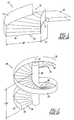
- FIG. 1 wherein there is shown a conventional spiral chute 10 including inner and outer side walls 12 and 14 separated by a lower conveying surface 16.
- the chute 10 is designed so that items fed to an entry port 18 from a conveyor belt 20 are delivered to a discharge location, for example a receiving station, not shown, by way of an output port 22.
- Spiral chutes are specified by their degree of rotation, direction, width and inside radius.
- Figure 1 depicts a left-hand spiral chute which is, for example 152.4 cm, (60 inches) wide and having a 30.48 cm (12 inch) inside radius.
- the degree of rotation can be as large or small as the particular application requires.
- Figure 2 shows a spiral chute 24 having 540° of rotation. It includes an outer wall 26 and a conveying surface 28 which spirals around a hub 30 in the form of a helix which is aligned with a vertical axis 32.
- An entry port 34 is located at the top of the chute 24, while an output port 36 is located at the bottom or discharge end of the chute.
- the elevation change between the input port 34 and the output port 36 is shown, for example, comprising 304.8 cm or 3.048 m (120 inches or 10 feet).
- the chute 24 can be used to convey items downward 3.048m (10 feet) in elevation. Due to its significant length, however, it can also be used as a accumulation device for buffering items prior to downstream processing past the output port 36.
- spiral chute shown in Figure 2 One such application for the spiral chute shown in Figure 2 is for air express parcel delivery.
- the advantage of the spiral chute, such as shown in Figure 2 is that it consumes less floor space and therefore has a smaller "footprint" than a straight chute.
- a known improvement in this concept involves the nesting of two spiral chutes about the same vertical axis.
- a configuration is shown in Figure 3 where a second 540 degree spiral chute 38 is located on top of the chute 24.
- the chute 38 consists of an outer wall 40 and a conveying surface 42, and having a top entry port 44 and an output port 46.
- Such an arrangement results in a composite double helix spiral chute configuration being provided as shown by reference numeral 48. It is to be noted, however, that in the double helix configuration 48 shown in Figure 3, the two chutes 24 and 38 are mutually rotated 180° so that the two top entry ports 34 and 44 are rotated 180° with respect to one another as are the two output ports 36 and 46.
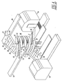
- Such an arrangement has particular utility in a loading system such as shown in Figure 4 where two separate sorting machines 50 and 52, also referred to simply as sorters, having respective diverter mechanisms 51 and 53, convey items in opposite directions from two separate sources, not shown.
- This type of material handling system is widely used in the automated and conventional sortation industry for loading a pair of containers 54 and 56 respectively located at the discharge ends of the two spiral chutes 24 and 38 as shown.
- top entry input port 44 is located along the side of sorter 52 opposite the diverter mechanism 53.
- the top entry input port 34 of chute 24 is located to the side of sorter 50 opposite diverter mechanism 51.
- the diverter mechanism 53 operates to divert items in the direction b where they enter the top entry input port 42 where they travel down the chute 38 to the discharge end at output port 46.
- an inner side wall member 62 is located across from the diverter 53 at the input port 42.
- each of the spiral chutes 24 and 38 connects to a respective sorting machine 50 or 52.
- sorting In the event that an item such as a package on conveyor 52 needs to be directed to chute 24 rather than chute 38, it must undergo a process known as "presorting". Otherwise, it must be resent via sorter 50 after it has been handled by the sorter 52. This latter process is called “rehandling". Presorting requires additional personnel and/or additional equipment. Rehandling acts to reduce the effective processing rate of the system, since equipment is utilized twice for handling the same item. Also, any given sorting machine can only process so many pieces in a given amount of time.
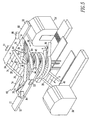
- the chutes 24 and 38 are now fitted with side entry input ports 66 and 68, respectively, which are formed in outer side walls 26 and 40 downstream of the top entry input ports 34 and 44.
- the side entry input port 66 for the chute 24 includes a downwardly sloping conveyor surface 70 from the top surface 72 of sorter 52 where it is joined to the chute conveying surface 28.
- the side entry input port 66 also includes a pair of downward angulating side walls, one of which is shown by reference numeral 74.
- the side entry port 68 includes a downward sloping conveyor surface 76 having a top edge 78 abutting the top surface 80 of the sorter 50.
- the downwardly sloping conveying surface 76 is joined to the conveying surface 42 downstream of the top entry input port 44.
- a pair of angulated side walls 82 and 84 help to guide items onto the spiral conveyor surface 42.
- the sorter 52 includes a second diverter mechanism 84 is located forward of the diverter mechanism 53 and a second diverter mechanism 86 is located on sorter 50 forward of the diverter mechanism 51.
- items traveling on the surface 72 of the sorter 52 can be diverted to either chute 24 by activation of diverter mechanism 84 which diverts the items to the side entry port 66, or can divert items to chute 38 by activation of diverter mechanism 53 which diverts items to the top input port 44 of chute 38.
- the structure of Figure 5 does not disrupt the flow of items coming from the top of the chute. It should also be noted that the location of the side entry ports 66 and 68 can be made at any location along the outer walls 26 and 40 depending upon the intended application.
Landscapes
- Chutes (AREA)
- Discharge Of Articles From Conveyors (AREA)
- Microwave Tubes (AREA)
- Endoscopes (AREA)
- Carriages For Children, Sleds, And Other Hand-Operated Vehicles (AREA)
Claims (20)
- Système de manutention de matériau comprenant une paire de trieuses (50, 52) transportant des articles d'une ou plusieurs sources de livraison vers une paire de stations de réception (54, 56), comprenant :deux rampes de livraison incurvées à double entrée (24, 38), emboítées, ayant un axe vertical commun (32) et situées l'une au dessus de l'autre relativement proches de la paire de trieuses (50, 52) pour livrer sélectivement des articles de l'une ou l'autre de ladite paire de trieuses (50, 52) à l'une ou l'autre de ladite paire de stations de réception (54, 56), chacune desdites rampes (24, 38) comprenant un premier et un second orifice d'entrée (34, 44, 66, 68) et un orifice de sortie commun (36, 46), ledit premier orifice d'entrée (34, 44) étant orienté vers une trieuse de ladite paire de trieuses (50, 52) et ledit second orifice d'entrée (66, 68) étant orienté vers l'autre trieuse de ladite paire de trieuses (50, 52), et dans lequel les articles déroutés des deux desdites trieuses (50, 52) peuvent être livrés sélectivement audit même orifice de sortie (36, 46), et dans lequel ledit orifice de sortie de l'une desdites rampes (24, 38) est situé au niveau de son extrémité de décharge adjacente à une station de réception de ladite paire des stations de réception (54, 56) et ledit orifice de sortie de l'autre desdites rampes est situé au niveau de son extrémité de décharge au niveau de l'autre station de réception de ladite paire de stations de réception (54, 56), moyennant quoi une condition pour pré-trier et remanipuler les articles qui sont transportés via les trieuses (50, 52) est supprimée tout en proposant en même temps la redondance dans le cas où l'une des trieuses (50, 52) n'est pas en service.
- Système de manutention de matériau selon la revendication 1, dans lequel ledit premier orifice d'entrée (34, 44) de chacune desdites rampes (24, 38) comprend un orifice d'entrée supérieure situé au niveau d'une extrémité de la rampe, et le second orifice d'entrée (66, 68) comprend un orifice d'entrée latérale situé vers l'intérieur dudit orifice d'entrée supérieure (34, 44), à une distance prédéterminée en aval de celui-ci.
- Système de manutention de matériau selon la revendication 1, dans lequel lesdites deux rampes de livraison (24, 38) incurvées comprennent des rampes en spirale pour transporter des articles d'une élévation supérieure à une élévation inférieure, et dans lequel ledit premier orifice d'entrée (34, 44) de chacune desdites rampes (24, 38) comprend un orifice d'entrée supérieure situé à une extrémité de la rampe et le second orifice d'entrée (66, 68) de chacune desdites rampes (24, 38) comprend un orifice d'entrée latérale en interface avec une paroi latérale (26, 40) à rayon externe de la rampe au niveau d'un emplacement prédéterminé en aval de l'orifice d'entrée supérieure.
- Système de manutention de matériau selon la revendication 3, dans lequel lesdites rampes de livraison en spirale (24, 48) proposent une configuration de rampe de livraison à double hélice.
- Système de manutention de matériau selon la revendication 4, dans lequel les deux desdites rampes de livraison (24, 48) ont sensiblement la même taille afin de proposer une empreinte commune.
- Système de manutention de matériau selon la revendication 5, dans lequel les rampes de livraison (24, 48) tournent à 180° l'une par rapport à l'autre, moyennant quoi les orifices d'entrée supérieure sont en face dans des directions opposées.
- Système de manutention de matériau selon la revendication 6, dans lequel la paire de trieuses (50, 52) comprend des éléments de transport d'articles respectifs et dans lequel l'orifice d'entrée supérieure (34, 44) de l'une desdites rampes (24, 48) et l'orifice d'entrée latérale (66, 68) de l'autre desdites rampes sont orientés vers l'un des éléments de transport d'article pour recevoir des articles déroutés à partir de ceux-ci et dans lequel l'orifice d'entrée supérieure (34, 44) de l'autre desdites rampes et l'orifice d'entrée latérale (66, 68) de ladite une rampe sont orientés vers l'autre élément de transport d'article pour recevoir des articles déroutés à partir de celui-ci.
- Système de manutention de matériau selon la revendication 7, dans lequel lesdits éléments de transport d'article sont situés à un même niveau supérieur et la paire de stations de réception (54, 56) est située à un même niveau inférieur.
- Système de manutention de matériau selon la revendication 8, dans lequel les deux desdites rampes (24, 48) comprennent des rampes à spirales à 540°.
- Système de manutention de matériau selon la revendication 1, dans lequel ladite paire de trieuses (50, 52) comprend des mécanismes dérouteurs (51, 86 et 53, 84) pour dérouter sélectivement des articles vers lesdits premier et second orifices d'entrée (34, 44 et 66, 68).
- Système de manutention de matériau selon la revendication 9, et comprenant en outre des premier et second mécanismes dérouteurs (51, 86 et 53, 84) sur chacune de ladite paire de trieuses (50, 52) pour détourner des articles à partir de celle-ci vers l'orifice d'entrée supérieure (34) de l'une desdites rampes (24) et l'orifice d'entrée latérale (68) de l'autre desdites rampes (58).
- Procédé de manutention de matériau, comprenant les étapes visant à :transporter des articles à partir de sources séparées vers une paire de rampes de livraison (24, 48) incurvées, emboítées, chaque rampe ayant un orifice d'entrée, d'entrée supérieure ( 34, 44), un orifice d'entrée, d'entrée latérale (66, 68), et un orifice de sortie commune (36, 46),dérouter sélectivement les articles provenant de l'une desdites sources vers chacun parmi l'orifice d'entrée, d'entrée supérieure (34, 44) de la une rampe de ladite paire de rampes (24, 48) et l'orifice de réception d'entrée latérale (66, 68) de l'autre rampe de ladite paire de rampes (24, 48),dérouter sélectivement les articles provenant de l'autre desdites sources vers chacun parmi l'orifice de réception d'entrée supérieure (66, 68) de l'autre rampe desdites rampes (24, 48) et l'orifice de réception d'entrée latérale (66, 68) de ladite une rampe desdites rampes (24, 48),livrer les articles déroutés via l'orifice de sortie au niveau d'une extrémité de décharge de ladite une rampe de ladite paire de rampes (24, 48) à une première station de réception ; etlivrer les articles déroutés via l'orifice de sortie au niveau d'une extrémité de décharge de ladite autre rampe à une seconde station de réception.
- Procédé selon la revendication 12, dans lequel lesdites rampes de livraison (24, 48) comprennent des rampes à spirale.
- Procédé selon la revendication 13 et comprenant en outre l'étape consistant à agencer lesdites rampes à spirale (24, 48) en une configuration à double hélice.
- Procédé selon la revendication 14 et comprenant en outre l'étape consistant à former les deux orifices d'entrée latérale (34, 44) dans une paroi latérale externe (26, 40) desdites rampes à spirale (24, 4).
- Procédé selon la revendication 15, dans lequel l'orifice d'entrée, d'entrée supérieure (34, 44) des deux desdites rampes ( 24, 48) est situé au niveau de l'extrémité supérieure desdites rampes et les orifices d'entrée latérale (66, 68) des deux desdites rampes (24, 48) sont situés à une distance prédéterminée vers l'intérieur de l'orifice d'entrée, d'entrée supérieure ( 34, 44) respectif.
- Procédé selon la revendication 16 dans lequel les deux desdites rampes (24, 48) comprennent des rampes ayant sensiblement la même taille afin de proposer une empreinte commune.
- Procédé selon la revendication 17 et comprenant en outre l'étape consistant à faire tourner une rampe (24, 48) par rapport à l'autre rampe (24, 48) de sorte que ses orifices d'entrée supérieure (34, 44) sont situés à 180° à distance l'un de l'autre.
- Procédé selon la revendication 17 et comprenant en outre l'étape consistant à faire tourner une rampe (24, 48) par rapport à l'autre rampe (24, 48) de sorte que les orifices de sortie (36, 46) respectifs sont situés à 180° à distance l'un de l'autre.
- Procédé selon la revendication 17, dans lequel les deux desdites rampes (24, 48) comprennent des rampes à spirale à 540°.
Applications Claiming Priority (2)
| Application Number | Priority Date | Filing Date | Title |
|---|---|---|---|
| US594163 | 2000-06-15 | ||
| US09/594,163 US6371275B1 (en) | 2000-06-15 | 2000-06-15 | Dual entry-double helix spiral chute |
Publications (2)
| Publication Number | Publication Date |
|---|---|
| EP1167246A1 EP1167246A1 (fr) | 2002-01-02 |
| EP1167246B1 true EP1167246B1 (fr) | 2004-09-22 |
Family
ID=24377796
Family Applications (1)
| Application Number | Title | Priority Date | Filing Date |
|---|---|---|---|
| EP01114224A Expired - Lifetime EP1167246B1 (fr) | 2000-06-15 | 2001-06-12 | Rampe hélicoidale à entrée double et à double hélice |
Country Status (5)
| Country | Link |
|---|---|
| US (1) | US6371275B1 (fr) |
| EP (1) | EP1167246B1 (fr) |
| AT (1) | ATE276946T1 (fr) |
| CA (1) | CA2350382A1 (fr) |
| DE (1) | DE60105698T2 (fr) |
Families Citing this family (26)
| Publication number | Priority date | Publication date | Assignee | Title |
|---|---|---|---|---|
| CA2430200A1 (fr) * | 2003-05-28 | 2004-11-28 | Glopak Inc. | Systeme et methode d'ensachage a haute vitesse |
| US7185748B2 (en) * | 2004-03-11 | 2007-03-06 | Tritek Technologies, Inc. | Object transport and sorting assemblies and methods |
| DE102005062715B4 (de) * | 2005-12-28 | 2008-02-14 | Fette Gmbh | Vorrichtung zum Befüllen von Aufnahmebehältern mit den Produkten einer Rundläuferpresse |
| DE202006013956U1 (de) * | 2006-09-12 | 2008-01-31 | Gebr. Willach Gmbh | Warenannahmeautomat |
| NL2000404C2 (nl) | 2006-12-22 | 2008-06-25 | Ambaflex Internat B V | Transportinrichting. |
| NL2000635C1 (nl) * | 2007-05-07 | 2008-11-10 | Specialty Conveyor Bv | Inrichting en werkwijze voor het bufferen van producten. |
| DE202007009399U1 (de) * | 2007-07-04 | 2007-09-27 | Gebr. Willach Gmbh | Kombiniertes Warenlager |
| CN101652058A (zh) * | 2008-08-13 | 2010-02-17 | 深圳富泰宏精密工业有限公司 | 传送装置 |
| NL2002100C (en) | 2008-10-15 | 2010-04-16 | Specialty Conveyor Bv | A buffer conveyor having parallel tracks. |
| WO2012047119A1 (fr) * | 2010-10-06 | 2012-04-12 | Compac Technologies Limited | Configurations pour le transfert d'articles |
| US8556084B1 (en) | 2011-04-29 | 2013-10-15 | American Airlines, Inc. | Baggage cart handling system |
| AU2013290117B2 (en) * | 2012-07-11 | 2017-03-16 | Dematic Corp. | Crossbelt sorter system and method of sorting articles |
| CN103224116A (zh) * | 2013-04-16 | 2013-07-31 | 常熟市三骏精密刃具制造厂 | 出料收集装置 |
| USD846222S1 (en) * | 2015-02-13 | 2019-04-16 | Alternative Engineering, Inc. | Stepped spiral chute assembly having friction reduction panels |
| CN105396793B (zh) * | 2015-11-29 | 2017-10-31 | 重庆元创汽车整线集成有限公司 | 用于轴承套圈的分选装置 |
| CN105436089B (zh) * | 2015-11-29 | 2017-11-24 | 重庆元创汽车整线集成有限公司 | 用于轴承套圈的分选装置的工作方法 |
| CN105344615B (zh) * | 2015-11-29 | 2018-06-22 | 重庆元创汽车整线集成有限公司 | 用于轴承套圈的检测装置 |
| CN108584358B (zh) * | 2017-12-30 | 2024-02-13 | 深圳滨海航空文化科技有限公司 | 自动送餐流水线旋转系统及自动旋转送餐方法 |
| US10793358B1 (en) * | 2018-08-27 | 2020-10-06 | Amazon Technologies, Inc. | Spiral entry chute |
| USD890442S1 (en) * | 2018-09-28 | 2020-07-14 | PetSmart Home Office, Inc. | Spiral ramp for small animal habitat |
| CN109701902B (zh) * | 2019-03-14 | 2020-09-29 | 安徽鑫铱科技有限责任公司 | 一种色选机物料分拣装置及其分拣系统 |
| CN109926332B (zh) * | 2019-04-16 | 2020-09-25 | 南华大学 | 可多路同步分拣的快递分拣系统 |
| CN112722735A (zh) * | 2020-12-30 | 2021-04-30 | 哈尔滨铭川运输有限公司 | 一种物流运输高空卸载分类车和使用方法 |
| CN113320850B (zh) * | 2021-05-17 | 2024-07-30 | 中冶赛迪工程技术股份有限公司 | 一种筒仓及其布置结构 |
| CN117383132A (zh) * | 2023-10-11 | 2024-01-12 | 江苏业神物流设备有限公司 | 一种双通道分拣装置 |
| CN119158832A (zh) * | 2024-11-20 | 2024-12-20 | 安徽银球轴承有限公司 | 一种轴承加工的连续式清洗机 |
Family Cites Families (11)
| Publication number | Priority date | Publication date | Assignee | Title |
|---|---|---|---|---|
| US1194098A (en) * | 1916-08-08 | Fire-escape | ||
| US1090948A (en) * | 1906-12-01 | 1914-03-24 | Deere & Co | Conveyer. |
| US1074387A (en) * | 1909-06-11 | 1913-09-30 | Gravity Conveyor Company | Combined tray-conveyer and spiral chute. |
| US1351554A (en) * | 1918-12-14 | 1920-08-31 | Lamson Co | Conveyer |
| NL7708894A (nl) * | 1977-08-12 | 1979-02-14 | Ammeraal Nederland Bv | Spiraaltransporteur. |
| GB8334162D0 (en) | 1983-12-22 | 1984-02-01 | Rule & Son Ltd G O | Storage hopper/silo |
| DE3440609C1 (de) * | 1984-11-07 | 1985-08-01 | Krampe & Co Fertigung in Bergbaubedarf GmbH, Zweigniederlassung Pelkum, 4700 Hamm | Wendelrutsche für Berge |
| SE459726B (sv) * | 1988-07-26 | 1989-07-31 | Frigoscandia Contracting Ab | Transportanordning |
| DE9112622U1 (de) | 1991-10-10 | 1992-01-23 | Gebr. Wöhr GmbH & Co, 7080 Aalen | Wendelrutsche |
| US5413213A (en) * | 1992-07-25 | 1995-05-09 | Korber Ag | Apparatus for transporting mass flows of articles |
| US5887699A (en) * | 1992-11-20 | 1999-03-30 | Tharpe; John M. | System and method for conveying and sorting articles |
-
2000
- 2000-06-15 US US09/594,163 patent/US6371275B1/en not_active Expired - Fee Related
-
2001
- 2001-06-12 DE DE60105698T patent/DE60105698T2/de not_active Expired - Lifetime
- 2001-06-12 AT AT01114224T patent/ATE276946T1/de not_active IP Right Cessation
- 2001-06-12 EP EP01114224A patent/EP1167246B1/fr not_active Expired - Lifetime
- 2001-06-13 CA CA002350382A patent/CA2350382A1/fr not_active Abandoned
Also Published As
| Publication number | Publication date |
|---|---|
| US6371275B1 (en) | 2002-04-16 |
| CA2350382A1 (fr) | 2001-12-15 |
| DE60105698T2 (de) | 2005-10-06 |
| ATE276946T1 (de) | 2004-10-15 |
| DE60105698D1 (de) | 2004-10-28 |
| EP1167246A1 (fr) | 2002-01-02 |
Similar Documents
| Publication | Publication Date | Title |
|---|---|---|
| US6371275B1 (en) | Dual entry-double helix spiral chute | |
| US9624043B2 (en) | High rate bulk flow sortation | |
| US11999575B2 (en) | Parcel processing system and method including hybrid orientation active merge induction equipment | |
| US10022752B1 (en) | Package sorting module, system, and method of using the same | |
| US11142406B2 (en) | Automated parcel singulator | |
| EP3535206B1 (fr) | Goulottes de déviation dans des systèmes de transporteur de tri | |
| US10176662B2 (en) | Empties sorting device and empties return system | |
| KR20020044562A (ko) | 양 할당 컨베이어 시스템 | |
| US5887698A (en) | Method and apparatus for sorting articles received from vertically spaced platforms of a moving transport device | |
| US10793358B1 (en) | Spiral entry chute | |
| US6499604B1 (en) | Compound induction system | |
| KR20200025318A (ko) | 통합 물품 분류 시스템 | |
| CA2318168A1 (fr) | Systeme d'acheminement de contenants de courrier trie et procede associe | |
| WO2004016363A1 (fr) | Procedes et appareils de tri non individuel | |
| US12059711B2 (en) | System for sorting items to be sorted into target points, logically linked to their destination, in a matrix arrangement | |
| KR20200025317A (ko) | 물품 분류 시스템 | |
| KR20200001160A (ko) | 소형 물품 자동 분류 시스템 | |
| US20070084764A1 (en) | Bi-directional sort mechanism and method of use | |
| US20070090028A1 (en) | Sort mechanism and method of use | |
| JPH04112124A (ja) | 物品仕分け装置 | |
| US20070075000A1 (en) | Sort mechanism and method of use | |
| US12023716B2 (en) | Sorting layout for piece goods with cylindrical end position device | |
| US20250033896A1 (en) | Dynamic sorting of items in a conveyor system | |
| US20070012545A1 (en) | Separator and method of use | |
| JPH0750333Y2 (ja) | 搬送仕分け機用合流装置 |
Legal Events
| Date | Code | Title | Description |
|---|---|---|---|
| PUAI | Public reference made under article 153(3) epc to a published international application that has entered the european phase |
Free format text: ORIGINAL CODE: 0009012 |
|
| AK | Designated contracting states |
Kind code of ref document: A1 Designated state(s): AT BE CH CY DE DK ES FI FR GB GR IE IT LI LU MC NL PT SE TR |
|
| AX | Request for extension of the european patent |
Free format text: AL;LT;LV;MK;RO;SI |
|
| 17P | Request for examination filed |
Effective date: 20020604 |
|
| AKX | Designation fees paid |
Free format text: AT BE CH CY DE DK ES FI FR GB GR IE IT LI LU MC NL PT SE TR |
|
| 17Q | First examination report despatched |
Effective date: 20030610 |
|
| GRAP | Despatch of communication of intention to grant a patent |
Free format text: ORIGINAL CODE: EPIDOSNIGR1 |
|
| GRAP | Despatch of communication of intention to grant a patent |
Free format text: ORIGINAL CODE: EPIDOSNIGR1 |
|
| GRAS | Grant fee paid |
Free format text: ORIGINAL CODE: EPIDOSNIGR3 |
|
| GRAA | (expected) grant |
Free format text: ORIGINAL CODE: 0009210 |
|
| AK | Designated contracting states |
Kind code of ref document: B1 Designated state(s): AT BE CH CY DE DK ES FI FR GB GR IE IT LI LU MC NL PT SE TR |
|
| PG25 | Lapsed in a contracting state [announced via postgrant information from national office to epo] |
Ref country code: IT Free format text: LAPSE BECAUSE OF FAILURE TO SUBMIT A TRANSLATION OF THE DESCRIPTION OR TO PAY THE FEE WITHIN THE PRESCRIBED TIME-LIMIT;WARNING: LAPSES OF ITALIAN PATENTS WITH EFFECTIVE DATE BEFORE 2007 MAY HAVE OCCURRED AT ANY TIME BEFORE 2007. THE CORRECT EFFECTIVE DATE MAY BE DIFFERENT FROM THE ONE RECORDED. Effective date: 20040922 Ref country code: AT Free format text: LAPSE BECAUSE OF FAILURE TO SUBMIT A TRANSLATION OF THE DESCRIPTION OR TO PAY THE FEE WITHIN THE PRESCRIBED TIME-LIMIT Effective date: 20040922 Ref country code: BE Free format text: LAPSE BECAUSE OF FAILURE TO SUBMIT A TRANSLATION OF THE DESCRIPTION OR TO PAY THE FEE WITHIN THE PRESCRIBED TIME-LIMIT Effective date: 20040922 Ref country code: FI Free format text: LAPSE BECAUSE OF FAILURE TO SUBMIT A TRANSLATION OF THE DESCRIPTION OR TO PAY THE FEE WITHIN THE PRESCRIBED TIME-LIMIT Effective date: 20040922 Ref country code: CH Free format text: LAPSE BECAUSE OF FAILURE TO SUBMIT A TRANSLATION OF THE DESCRIPTION OR TO PAY THE FEE WITHIN THE PRESCRIBED TIME-LIMIT Effective date: 20040922 Ref country code: TR Free format text: LAPSE BECAUSE OF FAILURE TO SUBMIT A TRANSLATION OF THE DESCRIPTION OR TO PAY THE FEE WITHIN THE PRESCRIBED TIME-LIMIT Effective date: 20040922 Ref country code: LI Free format text: LAPSE BECAUSE OF FAILURE TO SUBMIT A TRANSLATION OF THE DESCRIPTION OR TO PAY THE FEE WITHIN THE PRESCRIBED TIME-LIMIT Effective date: 20040922 Ref country code: NL Free format text: LAPSE BECAUSE OF FAILURE TO SUBMIT A TRANSLATION OF THE DESCRIPTION OR TO PAY THE FEE WITHIN THE PRESCRIBED TIME-LIMIT Effective date: 20040922 |
|
| REG | Reference to a national code |
Ref country code: GB Ref legal event code: FG4D |
|
| REG | Reference to a national code |
Ref country code: CH Ref legal event code: EP |
|
| REG | Reference to a national code |
Ref country code: IE Ref legal event code: FG4D |
|
| REF | Corresponds to: |
Ref document number: 60105698 Country of ref document: DE Date of ref document: 20041028 Kind code of ref document: P |
|
| PG25 | Lapsed in a contracting state [announced via postgrant information from national office to epo] |
Ref country code: GR Free format text: LAPSE BECAUSE OF FAILURE TO SUBMIT A TRANSLATION OF THE DESCRIPTION OR TO PAY THE FEE WITHIN THE PRESCRIBED TIME-LIMIT Effective date: 20041222 Ref country code: DK Free format text: LAPSE BECAUSE OF FAILURE TO SUBMIT A TRANSLATION OF THE DESCRIPTION OR TO PAY THE FEE WITHIN THE PRESCRIBED TIME-LIMIT Effective date: 20041222 Ref country code: SE Free format text: LAPSE BECAUSE OF FAILURE TO SUBMIT A TRANSLATION OF THE DESCRIPTION OR TO PAY THE FEE WITHIN THE PRESCRIBED TIME-LIMIT Effective date: 20041222 |
|
| PG25 | Lapsed in a contracting state [announced via postgrant information from national office to epo] |
Ref country code: ES Free format text: LAPSE BECAUSE OF FAILURE TO SUBMIT A TRANSLATION OF THE DESCRIPTION OR TO PAY THE FEE WITHIN THE PRESCRIBED TIME-LIMIT Effective date: 20050102 |
|
| REG | Reference to a national code |
Ref country code: CH Ref legal event code: PL |
|
| NLV1 | Nl: lapsed or annulled due to failure to fulfill the requirements of art. 29p and 29m of the patents act | ||
| PG25 | Lapsed in a contracting state [announced via postgrant information from national office to epo] |
Ref country code: LU Free format text: LAPSE BECAUSE OF NON-PAYMENT OF DUE FEES Effective date: 20050612 Ref country code: CY Free format text: LAPSE BECAUSE OF FAILURE TO SUBMIT A TRANSLATION OF THE DESCRIPTION OR TO PAY THE FEE WITHIN THE PRESCRIBED TIME-LIMIT Effective date: 20050612 |
|
| PG25 | Lapsed in a contracting state [announced via postgrant information from national office to epo] |
Ref country code: IE Free format text: LAPSE BECAUSE OF NON-PAYMENT OF DUE FEES Effective date: 20050613 |
|
| ET | Fr: translation filed | ||
| PG25 | Lapsed in a contracting state [announced via postgrant information from national office to epo] |
Ref country code: MC Free format text: LAPSE BECAUSE OF NON-PAYMENT OF DUE FEES Effective date: 20050630 |
|
| PLBE | No opposition filed within time limit |
Free format text: ORIGINAL CODE: 0009261 |
|
| STAA | Information on the status of an ep patent application or granted ep patent |
Free format text: STATUS: NO OPPOSITION FILED WITHIN TIME LIMIT |
|
| 26N | No opposition filed |
Effective date: 20050623 |
|
| REG | Reference to a national code |
Ref country code: IE Ref legal event code: MM4A |
|
| PG25 | Lapsed in a contracting state [announced via postgrant information from national office to epo] |
Ref country code: PT Free format text: LAPSE BECAUSE OF NON-PAYMENT OF DUE FEES Effective date: 20050222 |
|
| REG | Reference to a national code |
Ref country code: GB Ref legal event code: 732E Free format text: REGISTERED BETWEEN 20110428 AND 20110504 |
|
| REG | Reference to a national code |
Ref country code: FR Ref legal event code: TP Owner name: NORTHROP GRUMMAN SYSTEMS CORPORATION, US Effective date: 20120314 |
|
| REG | Reference to a national code |
Ref country code: DE Ref legal event code: R082 Ref document number: 60105698 Country of ref document: DE Representative=s name: NEUGEBAUER, JUERGEN, DIPL.-PHYS.UNIV. M.A./SUN, DE |
|
| REG | Reference to a national code |
Ref country code: DE Ref legal event code: R081 Ref document number: 60105698 Country of ref document: DE Owner name: NORTHROP GRUMMAN SYSTEMS CORPORATION (N.D.GES., US Free format text: FORMER OWNER: NORTHROP GRUMMAN CORP., LOS ANGELES, CALIF., US Effective date: 20130205 Ref country code: DE Ref legal event code: R082 Ref document number: 60105698 Country of ref document: DE Representative=s name: NEUGEBAUER, JUERGEN, DIPL.-PHYS.UNIV. M.A./SUN, DE Effective date: 20130205 Ref country code: DE Ref legal event code: R081 Ref document number: 60105698 Country of ref document: DE Owner name: NORTHROP GRUMMAN SYSTEMS CORPORATION (N.D.GES., US Free format text: FORMER OWNER: NORTHROP GRUMMAN CORP., LOS ANGELES, US Effective date: 20130205 |
|
| PGFP | Annual fee paid to national office [announced via postgrant information from national office to epo] |
Ref country code: GB Payment date: 20140618 Year of fee payment: 14 |
|
| PGFP | Annual fee paid to national office [announced via postgrant information from national office to epo] |
Ref country code: DE Payment date: 20140619 Year of fee payment: 14 |
|
| PGFP | Annual fee paid to national office [announced via postgrant information from national office to epo] |
Ref country code: FR Payment date: 20140619 Year of fee payment: 14 |
|
| REG | Reference to a national code |
Ref country code: DE Ref legal event code: R119 Ref document number: 60105698 Country of ref document: DE |
|
| GBPC | Gb: european patent ceased through non-payment of renewal fee |
Effective date: 20150612 |
|
| REG | Reference to a national code |
Ref country code: FR Ref legal event code: ST Effective date: 20160229 |
|
| PG25 | Lapsed in a contracting state [announced via postgrant information from national office to epo] |
Ref country code: DE Free format text: LAPSE BECAUSE OF NON-PAYMENT OF DUE FEES Effective date: 20160101 Ref country code: GB Free format text: LAPSE BECAUSE OF NON-PAYMENT OF DUE FEES Effective date: 20150612 |
|
| PG25 | Lapsed in a contracting state [announced via postgrant information from national office to epo] |
Ref country code: FR Free format text: LAPSE BECAUSE OF NON-PAYMENT OF DUE FEES Effective date: 20150630 |