EP1167254A2 - Dispositif d'alimentation en feuilles comprenant un plenum d'admission d'air avec joint - Google Patents
Dispositif d'alimentation en feuilles comprenant un plenum d'admission d'air avec joint Download PDFInfo
- Publication number
- EP1167254A2 EP1167254A2 EP01113979A EP01113979A EP1167254A2 EP 1167254 A2 EP1167254 A2 EP 1167254A2 EP 01113979 A EP01113979 A EP 01113979A EP 01113979 A EP01113979 A EP 01113979A EP 1167254 A2 EP1167254 A2 EP 1167254A2
- Authority
- EP
- European Patent Office
- Prior art keywords
- sheets
- sheet
- compilation
- paper
- seal
- Prior art date
- Legal status (The legal status is an assumption and is not a legal conclusion. Google has not performed a legal analysis and makes no representation as to the accuracy of the status listed.)
- Granted
Links
Images


Classifications
-
- B—PERFORMING OPERATIONS; TRANSPORTING
- B65—CONVEYING; PACKING; STORING; HANDLING THIN OR FILAMENTARY MATERIAL
- B65H—HANDLING THIN OR FILAMENTARY MATERIAL, e.g. SHEETS, WEBS, CABLES
- B65H3/00—Separating articles from piles
- B65H3/08—Separating articles from piles using pneumatic force
- B65H3/0808—Suction grippers
- B65H3/0883—Construction of suction grippers or their holding devices
Definitions
- This invention relates generally to an electronic reprographic printing system, and more particularly concerns feeder apparatus process for improving feeding of compilations of recording sheets that often accompanies this general method of reproduction and printing.
- a light image of an original to be copied or printed is typically recorded in the form of a latent electrostatic image upon a photosensitive member, with a subsequent rendering of the latent image visible by the application of electroscopic marking particles, commonly referred to as toner.
- the visual toner image can be either fixed directly upon the photosensitive member or transferred from the member to another support medium, such as a sheet of plain paper. To render this toner image permanent, the image must be "fixed” or “fused” to the paper, generally by the application of heat and pressure.
- a sheet feeding apparatus for feeding a compilation of sheets in a process direction to a process station, comprising: a sheet tray for holding said compilation of sheets; an air plenum, positioned above said compilation of sheets, said plenum including a corrugated surface having a first set of ribs at a first height and a second set of ribs at a second height; and a blower for generating a vacuum force in said air plenum to drive one of said compilation of sheets into contact with said corrugated surface.
- An object of the present invention is a sheet feeder apparatus.
- air is used to help sheet separation, fluff sheet up, acquire sheet from the media tray and remove extra sheets away from the sheet being fed.
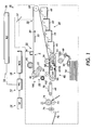
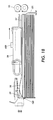
- Figure 1 is a schematic elevational view showing an electrophotographic printing machine which incorporates features of the present invention therein. It will become evident from the following discussion that the present invention is equally well suited for use in a wide variety of copying and printing systems, and is not necessarily limited in its application to the particular system shown herein.
- a color or black/white original document 38 is positioned on a raster input scanner (RIS), indicated generally by the reference numeral 10.
- RIS raster input scanner
- the RIS contains document illumination lamps, optics, a mechanical scanning drive, and a charge coupled device (CCD array).
- CCD array charge coupled device
- the RIS captures the entire image from original document 38 and converts it to a series of raster scan lines and moreover measures a set of primary color densities, i.e. red, green and blue densities, at each point of the original document.
- This information is transmitted as electrical signals to an image processing system (IPS), indicated generally by the reference numeral 12.
- IPS 12 converts the set of red, green and blue density signals to a set of colorimetric coordinates.
- IPS 12 contains control electronics which prepare and manage the image data flow to a raster output scanner (ROS), indicated generally by the reference numeral 16.
- a user interface (UI), indicated generally by the reference numeral 14, is in communication with IPS 12.
- UI 14 enables an operator to control the various operator adjustable functions. The operator actuates the appropriate keys of UI 14 to adjust the parameters of the copy.
- UI 14 may be a touch screen, or any other suitable control panel, providing an operator interface with the system.
- the output signal from UI 14 is transmitted to IPS 12.
- IPS 12 transmits signals corresponding to the desired image to ROS 16, which creates the output copy image.
- ROS 16 includes a laser with rotating polygon mirror blocks. Preferably, a nine facet polygon is used.
- ROS 16 illuminates, via mirror 37, the charged portion of a photoconductive belt 20 of a printer or marking engine, indicated generally by the reference numeral 18, at a rate of about 400 pixels per inch, to achieve a set of subtractive primary latent images.
- ROS 16 will expose the photoconductive belt 20 to record three latent images which correspond to the signals transmitted from IPS 12.
- One latent image is developed with cyan developer material.
- Another latent image is developed with magenta developer material and the third latent image is developed with yellow developer material.
- These developed images are transferred to a copy sheet in superimposed registration with one another to form a multicolored image on the copy sheet. This multicolored image is then fused to the copy sheet forming a color copy.
- printer or marking engine 18 is an electrophotographic printing machine.
- Photoconductive belt 20 of marking engine 18 is preferably made from a polychromatic photoconductive material.
- the photoconductive belt 20 moves in the direction of arrow 22 to advance successive portions of the photoconductive surface sequentially through the various processing stations disposed about the path of movement thereof.
- Photoconductive belt 20 is entrained about transfer rollers 24 and 26, tensioning roller 28, and drive roller 30.
- Drive roller 30 is rotated by a motor 32 coupled thereto by suitable means such as a belt drive. As roller 30 rotates, it advances belt 20 in the direction of arrow 22.
- a portion of photoconductive belt 20 passes through a charging station, indicated generally by the reference numeral 33.
- a corona generating device 34 charges photoconductive belt 20 to a relatively high, substantially uniform potential.
- Exposure station 35 receives a modulated light beam corresponding to information derived by RIS 10 having multicolored original document 38 positioned thereat.
- the modulated light beam impinges on the surface of photoconductive belt 20.
- the beam illuminates the charged portion of the photoconductive belt to form an electrostatic latent image.
- the photoconductive belt 20 is exposed three times to record three latent images thereon.
- the belt advances such latent images to a development station, indicated generally by the reference numeral 39.
- the development station includes four individual developer units indicated by reference numerals 40, 42, 44, and 46.
- the developer units are of a type generally referred to in the art as "magnetic brush development units.”
- a magnetic brush development system employs a magnetizable developer material including magnetic carrier granules having toner particles adhering triboelectrically thereto.
- the developer material is continually brought through a directional flux field to form a brush of developer material.
- the developer material is constantly moving so as to continually provide the brush with fresh developer material. Development is achieved by bringing the brush of developer material into contact with the photoconductive surface.
- Developer units 40, 42, and 44, respectively, apply toner particles of a specific color which corresponds to the compliment of the specific color separated electrostatic latent image recorded on the photoconductive surface.
- each of the toner particles is adapted to absorb light within a preselected spectral region of the electromagnetic wave spectrum.
- an electrostatic latent image formed by discharging the portions of charge on the photoconductive belt 20 corresponding to the green regions of the original document will record the red and blue portions as areas of relatively high charge density on photoconductive belt 20, while the green areas will be reduced to a voltage level ineffective for development.
- the charged areas are then made visible by having developer unit 40 apply green absorbing (magenta) toner particles onto the electrostatic latent image recorded on photoconductive belt 20.
- a blue separation is developed by developer unit 42 with blue absorbing (yellow) toner particles, while the red separation is developed by developer unit 44 with red absorbing (cyan) toner particles.
- Developer unit 46 contains black toner particles and may be used to develop the electrostatic latent image formed from a black and white original document.
- Each of the developer units is moved into and out of an operative position. In the operative position, the magnetic brush is substantially adjacent the photoconductive belt, while in the nonoperative position, the magnetic brush is spaced therefrom.
- each developer unit 40, 42, 44, and 46 is shown in the operative position.
- During development of each electrostatic latent image only one developer unit is in the operative position, while the remaining developer units are in the nonoperative position. This ensures that each electrostatic latent image is developed with toner particles of the appropriate color without commingling.
- Transfer station 65 includes a transfer zone, generally indicated by reference numeral 64. In transfer zone 64, the toner image is transferred to a sheet of support material, such as plain paper amongst others.
- a sheet transport apparatus indicated generally by the reference numeral 48, moves the sheet into contact with photoconductive belt 20.
- Sheet transport 48 has a pair of spaced belts 54 entrained about a pair of substantially cylindrical rollers 50 and 52.
- a sheet gripper (not shown in Figure 1) extends between belts 54 and moves in unison therewith. A sheet is advanced from a stack of sheets 56 disposed on a tray.
- a feeder 58 advances the uppermost sheet from stack 56 onto a pre-transfer transport 60.
- Transport 60 advances a sheet (not shown in Figure 1) to sheet transport 48.
- the sheet is advanced by transport 60 in synchronism with the movement of the sheet gripper.
- the leading edge of the sheet arrives at a preselected position, i.e. a loading zone, to be received by the open sheet gripper.
- the sheet gripper then closes securing the sheet thereto for movement therewith in a recirculating path.
- the leading edge of the sheet is secured releasably by the sheet gripper.
- belts 54 move in the direction of arrow 62, the sheet moves into contact with the photoconductive belt 20, in synchronism with the toner image developed thereon.
- a gas directing mechanism (not shown in Figure 1) directs a flow of gas onto the sheet to urge the sheet toward the developed toner image on photoconductive belt 20 so as to enhance contact between the sheet and the developed toner image in the transfer zone.
- a corona generating device 66 charges the backside of the sheet to the proper magnitude and polarity for attracting the toner image from photoconductive belt 20 thereto. The sheet remains secured to the sheet gripper so as to move in a recirculating path for three cycles. In this way, three different color toner images are transferred to the sheet in superimposed registration with one another.
- the sheet may move in a recirculating path for four cycles when under color black removal is used.
- Each of the electrostatic latent images recorded on the photoconductive surface is developed with the appropriately colored toner and transferred, in superimposed registration with one another, to the sheet to form the multicolor copy of the colored original document.
- the sheet transport system directs the sheet to a vacuum conveyor 68.
- Vacuum conveyor 68 transports the sheet, in the direction of arrow 70, to a fusing station, indicated generally by the reference numeral 71, where the transferred toner image is permanently fused to the sheet.
- the fusing station includes a heated fuser roll 74 and a pressure roll 72.
- the sheet passes through the nip defined by fuser roll 74 and pressure roll 72.
- the toner image contacts fuser roll 74 so as to be affixed to the sheet.
- the sheet is advanced by a pair of rolls 76 to a catch tray 78 for subsequent removal therefrom by the machine operator.
- the final processing station in the direction of movement of photoconductive belt 20, as indicated by arrow 22, is a photoreceptor cleaning station
- feeder station 58 of the present invention Further details of the construction and operation of feeder station 58 of the present invention are provided below referring to Figures 2 through 5.
- the sequence of operation of the sheet feeder of the present invention is as follows. A stack of paper 56 is placed into the elevator paper tray 120.
- an adaptive fluffer 140 has an air openings 401.
- the adaptive fluffer 140 is arranged such that it may inject air between sheets in the stack and on top surface of the sheet to be fed.
- the air pressure between sheets helps separate sheets, i.e. puff the sheets up.
- the combined effects improve the speed of the sheet acquisition speed and ensure a single sheet feed.
- the fluffer consists of support structure 410 and plate 415 having a Venturi plate portion 405 and regulating plate portion 420.
- Regulating plate portion 420 has an area 427 which permits air to go through and a cross-section area 426 which limits air low.
- the Venturi plate portion 405 Before paper is fluffed, the Venturi plate portion 405 is flat against the stack of paper 56. When paper is fluffed, paper will lift up the Venturi plate portion 405. When the paper moves up, its motion will transfer to the top position 425. It in turn pivots the regulating plate of the fluffer. The pivoting motion of Venturi plate portion 405 causes a cross-section area 426 of regulating plate portion 420 to limit the airflow.
- the Venturi plate is angled relative to support structure 410 so that whatever height the stack is at the gap area 615 remains substantially the same. This maintans the airflow on the stack to be consistent as the stack height changes. Both of these effects regulates the amount of fluffing to prevent over fluffing and keeps paper from being packed near the top sheet of the paper. This obviates the problem of paper being packed at the top of the fluffed sheets. This problem is more acute in the regular fluffer system for lightweight paper; as it will result in multi-feeds.
- Adaptive fluffer also be used for the paper stack height sensing.
- a sensor assembly 610 is mounted on the Venturi plate and it is used to measure the paper latitude inside the paper tray. Sensor assembly detects the change in position of Venturi plate on the stack of sheets. The reading of the paper latitude is then used to adjust the paper tray by operating the tray elevator.
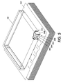
- feeder plenum 58 is located above the stack 56.
- the feeder plenum 58 includes a cavity which may be evacuated thereby forming a pressure differential.
- the vacuum paper contact surface 122 of the feeder plenu m 58 includes a series of small openings 124.
- Vacuum paper contact surface 122 employs a corrugated surface composed of a combination of variant sized ribs to reduce the bonding forces between paper surfaces thereby separating sheets on said vacuum paper contact surface 122.
- Seal 300 is positioned about the perimeter of plenum 58. Seal 300 is a floating and flexible seal between the vacuum plenum and paper stack. An advantageous feature of seal 300 is its adaptability. It bridges the gap between the vacuum plenum and the stack while not inhibiting the fluffing of the stack. Seal 300 is contoured to the out of flat conditions of the stack as sheets are drawn thereto. Seal 300 is also able to contour about sheet as the sheet is corrugated against the vacuum plenum corrugating area. Seal 300 is sufficient rigidity to not be drawn into the vacuum plenum box.
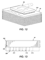
- Figure 13 shows one embodiment of seal 300.
- the sealing strip consists of small segments 312 flexibly connected together by pin 310. These segment 310 can freely rotate against each other in the in-plane direction, making it highly adaptable to the paper corrugation.
- the sealing has relatively much greater stiffness in the out-plane direction to prevent unwanted strip bending.
- the seal 300 has relative movement to the vacuum chamber. One way to accomplish that is to hang the seal 300 to the plenum 58 through small vertical channels 306 in which seal 300 rides up and down. The small channel will guide the up-down motion. Before the vacuum is applied, the seal 300 then slides down along the channel to lay on the paper stocks due to gravity. To prevent direct contact between the seal 300 and the stack (if such a contact is not wanted), one may also put stop 305 on the channels to limit the maximum movement.
- Sealing the vacuum plenum to the acquiring sheet has the added advantage that the fluffing and air knife pressure flows do not feed air into the vacuum plenum and make it difficult to create an acquiring vacuum.
- seal 300 comprising a plurality of contoured seal that fit the shape of the corrugated surface 122.
- the seals 302, 304, and 306 are attached to vacuum plenum perimeter through vertical channels or some other mechanisms which make the seals movable.
- the plenum vacuum is turned, on the front straight seal 302 (in conjunction with the other three perimeter seals 302, 304, and 306) applies the full vacuum pressure to the flat sheet with little or no leakage. This lifts the sheet (the fluffers also assist) until it is drawn into contact with the plenum box. At this time the sheet begins to corrugate around the fixed pattern of the plenum box. Heavyweight sheets corrugate very little and lightweight sheets corrugate more.
- seals 304 and 306 are shaped to provide a controlled amount of leakage. For heavier weight sheets larger vacuums are desired and for lighter weight sheets a lower pressure is desired.
- the seal 304 and 306 are so contoured to engage the sheet as it progressively corrugates while providing the appropriate leakage to reduce the pressure for lighter weight sheets.
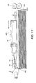
- drive assembly 600 is, attached to air plenum 58 for translating the acquire sheet's leading edge 57 into feed rollers.
- the drive assembly 600 translate the air plenum 58 initially in a reverse direction of movement of the feed rollers 58 so that a trailing edge 59 of the acquired sheets abuts against a portion 120 of the sheet tray to generate a buckle area in the acquired sheet.
- drive assembly translates air plenum in a direction of movement of the feed rollers 58 so that a lead edge of the acquired by the feed rollers 58 above flange 121.
- the drive assembly is shown in Figure 17. Applicants have found that the reverse motion buckles sheet 56 and cause a force to separate sheet 56 from a bottom sheet if the two sheets are stuck together.
- vacuum paper contact surface 122 To further reduce the likelihood of removing other sheets from the stack (i.e., to reduce multi-feeds), onto vacuum paper contact surface 122 employs a corrugated surface composed of a combination of variant sized ribs to reduce the bonding forces between paper surfaces thereby separating sheets on said vacuum paper contact surface 122.
- the paper bending also helps initiate gaps between the paper.
- the upper and lower parts of the beam undergo different kinds of deformation: One part is in extension and the other in compression. Therefore, if more than one sheet of paper is bent simultaneously, the bending motion will help the sheet separation.
- the corrugator in the VCF also helps the paper transportation because a sheet of corrugated paper is much stiffer than a sheet of flat paper, making the sheets much easier to handle as sheet are transported to feed rollers 58.
- VCF's use one single straight rib as the corrugator to generate gaps.
- the vacuum required is about 60 mmH 2 O and air flow rate to ensure the generation of the required vacuum (and to produce sufficient fluffer and air knife flow) is about 50 cm.
- the air blower must be large. It requires a high powered motor and it is a major contributor to copier and printer noise. Besides that, a higher vacuum may tend to leave marks on the paper surface, a consequence not welcomed on coated paper.
- the MVCF corrugator consists of a number of variant-height ribs ( Figures 3, 10, and 11).
- heavyweight paper deflects less than lightweight paper because of the different bending stiffness.
- the second sheet of paper When bent over a rib, the second sheet of paper will follow the first more closely with lightweight paper, i.e., if an identical rib is used, less gap will be generated in the lightweight paper than in the heavyweight paper.
- MVCF can feed both stiff and flexible paper.
- This corrugator was composed of ribs of four different heights. The four side ribs (two on each side) were the tallest, and the two center ribs were the second tallest. If we apply the same amount of load, the heavyweight paper deforms less than the lightweight paper so that if we use the proposed corrugator, the paper will deform into one, two, four, six, and other numbers of spans depending on the paper stiffness.
- Figure 10 illustrates the paper deformation when the proposed corrugator was used to acquire heavyweight paper.
- Figure 11 shows the deformed paper curvature when lightweight paper is acquired. The range of paper was from 60 GSM to 300 GSM. Comparing Figures 10 and-11 with Figures 8 and 9, we found the proposed corrugator generated bending and sliding motions on most parts of the corrugator surface for all grades of paper; while for the heavyweight paper the single corrugator feeder generated the sliding motion only in the center part of the corrugator. Since both the sliding and bending motions are essential in the sheet separation, we believe the proposed corrugator should perform better.
Landscapes
- Engineering & Computer Science (AREA)
- Mechanical Engineering (AREA)
- Sheets, Magazines, And Separation Thereof (AREA)
- Paper Feeding For Electrophotography (AREA)
Applications Claiming Priority (2)
| Application Number | Priority Date | Filing Date | Title |
|---|---|---|---|
| US591822 | 2000-06-12 | ||
| US09/591,822 US6398207B1 (en) | 2000-06-12 | 2000-06-12 | Sheet feeding apparatus having an air plenum with a seal |
Publications (3)
| Publication Number | Publication Date |
|---|---|
| EP1167254A2 true EP1167254A2 (fr) | 2002-01-02 |
| EP1167254A3 EP1167254A3 (fr) | 2004-01-02 |
| EP1167254B1 EP1167254B1 (fr) | 2006-05-03 |
Family
ID=24368090
Family Applications (1)
| Application Number | Title | Priority Date | Filing Date |
|---|---|---|---|
| EP01113979A Expired - Lifetime EP1167254B1 (fr) | 2000-06-12 | 2001-06-08 | Dispositif d'alimentation en feuilles comprenant un plenum d'admission d'air avec joint |
Country Status (4)
| Country | Link |
|---|---|
| US (1) | US6398207B1 (fr) |
| EP (1) | EP1167254B1 (fr) |
| JP (1) | JP4871455B2 (fr) |
| DE (1) | DE60119222T2 (fr) |
Cited By (2)
| Publication number | Priority date | Publication date | Assignee | Title |
|---|---|---|---|---|
| EP1270477A1 (fr) * | 2001-06-29 | 2003-01-02 | G.D Societ Per Azioni | Méthode et dispositif pour le transport d'éléments de feuilles pliés |
| EP1520817A1 (fr) * | 2003-10-02 | 2005-04-06 | Müller Martini Holding AG | Procédé et dispositif pour la production de livres reliés, de magazines ou de livrets |
Families Citing this family (21)
| Publication number | Priority date | Publication date | Assignee | Title |
|---|---|---|---|---|
| AUPR292501A0 (en) * | 2001-02-07 | 2001-03-01 | Silverbrook Research Pty. Ltd. | A method and apparatus (ART100) |
| AUPR315301A0 (en) * | 2001-02-19 | 2001-03-15 | Silverbrook Research Pty. Ltd. | An Apparatus (ART102) |
| US6581456B1 (en) * | 2002-01-07 | 2003-06-24 | Xerox Corporation | Substrate bending stiffness measurement method and system |
| US6669187B1 (en) * | 2002-06-13 | 2003-12-30 | Xerox Corporation | Rear jet air knife |
| US6863272B2 (en) | 2002-08-29 | 2005-03-08 | Xerox Corporation | Sheet feeding apparatus having an adaptive air fluffer |
| US6994340B2 (en) | 2002-09-12 | 2006-02-07 | Xerox Corporation | Sheet feeding apparatus having an air fluffer |
| US7237771B2 (en) * | 2004-01-15 | 2007-07-03 | Xerox Corporation | Feeder control system and method |
| US7540484B2 (en) | 2005-02-02 | 2009-06-02 | Xerox Corporation | System of opposing alternate higher speed sheet feeding from the same sheet stack |
| US7934718B2 (en) * | 2005-03-24 | 2011-05-03 | Xerox Corporation | Sheet feeding of faster rate printing systems with plural slower rate sheet feeders |
| US7328895B2 (en) * | 2005-05-13 | 2008-02-12 | Xerox Corporation | Sheet feeder vacuum feed head with variable corrugation |
| US7161511B2 (en) * | 2005-06-03 | 2007-01-09 | General Electric Company | Linearization system and method |
| JP2013006653A (ja) | 2011-06-23 | 2013-01-10 | Fuji Xerox Co Ltd | 記録材供給装置および画像形成装置 |
| JP2013010574A (ja) | 2011-06-28 | 2013-01-17 | Fuji Xerox Co Ltd | 媒体供給装置及び画像形成装置 |
| JP5842430B2 (ja) * | 2011-07-22 | 2016-01-13 | 富士ゼロックス株式会社 | 媒体供給装置および画像形成装置 |
| JP5768566B2 (ja) | 2011-07-29 | 2015-08-26 | 富士ゼロックス株式会社 | 媒体供給装置及び画像形成装置 |
| JP5786545B2 (ja) * | 2011-08-12 | 2015-09-30 | 富士ゼロックス株式会社 | 媒体供給装置及び画像形成装置 |
| JP6299240B2 (ja) * | 2014-02-03 | 2018-03-28 | 富士ゼロックス株式会社 | 給紙装置、画像形成装置 |
| JP7424018B2 (ja) | 2019-12-05 | 2024-01-30 | 富士フイルムビジネスイノベーション株式会社 | 記録材搬送装置および画像形成装置 |
| JP7490972B2 (ja) | 2020-02-03 | 2024-05-28 | 富士フイルムビジネスイノベーション株式会社 | 記録材搬送装置および画像形成装置 |
| JP7472516B2 (ja) | 2020-02-04 | 2024-04-23 | 富士フイルムビジネスイノベーション株式会社 | シート搬送装置及びシート搬送プログラム |
| JP7571430B2 (ja) | 2020-09-13 | 2024-10-23 | 富士フイルムビジネスイノベーション株式会社 | 媒体供給装置及びこれを用いた媒体処理装置 |
Family Cites Families (19)
| Publication number | Priority date | Publication date | Assignee | Title |
|---|---|---|---|---|
| US2060616A (en) * | 1935-09-05 | 1936-11-10 | New Jersey Machine Corp | Machine for applying adhesive |
| GB760891A (en) * | 1954-03-29 | 1956-11-07 | Dexter Folder Co | Improvements in or relating to sheet feeding apparatus |
| US3154306A (en) * | 1962-10-29 | 1964-10-27 | Harris Intertype Corp | Sheet-gripping sucker |
| GB966957A (en) * | 1963-02-18 | 1964-08-19 | F L Smidth & Company As | Improvements in and relating to the handling of fibrous cement sheets |
| US3272549A (en) * | 1965-01-13 | 1966-09-13 | Gen Electric | Materials handling device |
| US3501138A (en) * | 1967-08-30 | 1970-03-17 | Fmc Corp | Sheet dispenser |
| IL48833A (en) * | 1976-01-14 | 1980-11-30 | Amcor Bm | Insect electrocution device |
| DE2612952C2 (de) * | 1976-03-26 | 1984-08-30 | Albert Fezer Maschinenfabrik Gmbh, 7300 Esslingen | Vorrichtung zum Ergreifen einer verformbaren Platte mittels eines Saugnapfes |
| JPS5412832A (en) * | 1977-06-30 | 1979-01-30 | Ricoh Co Ltd | Air type sheet feeder |
| US4451028A (en) * | 1981-11-27 | 1984-05-29 | Xerox Corporation | Sheet feeding apparatus |
| US4627606A (en) * | 1984-12-13 | 1986-12-09 | Xerox Corporation | Bottom sheet feeding apparatus employing a combination slide plate and vacuum valve |
| JP2594651B2 (ja) * | 1989-10-16 | 1997-03-26 | 富士写真フイルム株式会社 | シート体枚葉機構用吸盤 |
| US5257776A (en) * | 1990-01-12 | 1993-11-02 | Fuji Photo Film Co., Ltd. | Device for feeding sheets having a detecting means for detecting misfeeds |
| JP2578238B2 (ja) * | 1990-03-20 | 1997-02-05 | シャープ株式会社 | 最上部シートの給送装置 |
| JP2827429B2 (ja) * | 1990-03-30 | 1998-11-25 | ミノルタ株式会社 | サクション給紙装置 |
| US5052675A (en) * | 1990-06-21 | 1991-10-01 | Xerox Corporation | Top vacuum corrugation feeder with aerodynamic drag separation |
| DE4128659C2 (de) * | 1990-09-06 | 1996-01-25 | Smc Kk | Saugnapf |
| US6149045A (en) * | 1995-04-26 | 2000-11-21 | Toshiba Tec Kabushiki Kaisha | Paper sheet supplying apparatus having a raised central region for preventing a paper sheet from skewing as the sheet is fed |
| US6264188B1 (en) * | 2000-06-12 | 2001-07-24 | Xerox Corporation | Sheet feeding apparatus having an adaptive air fluffer |
-
2000
- 2000-06-12 US US09/591,822 patent/US6398207B1/en not_active Expired - Lifetime
-
2001
- 2001-06-04 JP JP2001168130A patent/JP4871455B2/ja not_active Expired - Fee Related
- 2001-06-08 EP EP01113979A patent/EP1167254B1/fr not_active Expired - Lifetime
- 2001-06-08 DE DE60119222T patent/DE60119222T2/de not_active Expired - Lifetime
Cited By (4)
| Publication number | Priority date | Publication date | Assignee | Title |
|---|---|---|---|---|
| EP1270477A1 (fr) * | 2001-06-29 | 2003-01-02 | G.D Societ Per Azioni | Méthode et dispositif pour le transport d'éléments de feuilles pliés |
| US6945924B2 (en) | 2001-06-29 | 2005-09-20 | G.D Societa' Per Azioni | Method for conveying folded sheet elements |
| EP1520817A1 (fr) * | 2003-10-02 | 2005-04-06 | Müller Martini Holding AG | Procédé et dispositif pour la production de livres reliés, de magazines ou de livrets |
| US7419153B2 (en) | 2003-10-02 | 2008-09-02 | Muller Martini Holding Ag | Method and apparatus for producing bound books, magazines or brochures |
Also Published As
| Publication number | Publication date |
|---|---|
| JP4871455B2 (ja) | 2012-02-08 |
| DE60119222D1 (de) | 2006-06-08 |
| EP1167254A3 (fr) | 2004-01-02 |
| US6398207B1 (en) | 2002-06-04 |
| EP1167254B1 (fr) | 2006-05-03 |
| DE60119222T2 (de) | 2006-09-14 |
| JP2002019978A (ja) | 2002-01-23 |
Similar Documents
| Publication | Publication Date | Title |
|---|---|---|
| US6264188B1 (en) | Sheet feeding apparatus having an adaptive air fluffer | |
| US6398208B1 (en) | Sheet feeding apparatus having an air plenum with a leaky seal | |
| US6398207B1 (en) | Sheet feeding apparatus having an air plenum with a seal | |
| US6398206B1 (en) | Sheet feeding apparatus having an air plenum with a corrugated surface | |
| US6352255B1 (en) | Reversing shuttle feeder | |
| US6669187B1 (en) | Rear jet air knife | |
| US5518231A (en) | Self adjusting sheet gripping apparatus | |
| US6863272B2 (en) | Sheet feeding apparatus having an adaptive air fluffer | |
| US6945525B2 (en) | Sheet feeding apparatus having an adaptive air fluffer | |
| EP0493022B1 (fr) | Appareil d'avancement de feuilles | |
| US6994340B2 (en) | Sheet feeding apparatus having an air fluffer | |
| US7290764B2 (en) | Modular guide apparatus for tab stock received in a feeder tray | |
| US6505030B1 (en) | Pre-fuser transport assembly for handling a variety of sheets, and a reproduction machine having same | |
| JPH04234064A (ja) | 電子写真式印刷機 | |
| US5580044A (en) | Low aspect ratio, wide belt/long roller tracking system | |
| US5967511A (en) | Sheet registration assembly including a force reducing deskew roll | |
| US5533720A (en) | Sheet control baffle for use in an electrophotographic printing machine | |
| EP0617341B1 (fr) | Séparation de papier des bandes de photorécepteurs avec contrainte réduite | |
| US5227854A (en) | Sheet transport system with sheet velocity manipulation | |
| EP0493021B1 (fr) | Appareil de transport de feuilles | |
| US7310491B2 (en) | Non-gouging sheet stripper assembly | |
| US6212345B1 (en) | Image forming apparatus with different inertial conditions among image supports | |
| US7787814B2 (en) | Edge wear reducing pressure roller and an electrostatographic reproduction machine having same | |
| US5177541A (en) | Sheet transport system with improved gripper bar | |
| JP2003021941A (ja) | 画像形成装置 |
Legal Events
| Date | Code | Title | Description |
|---|---|---|---|
| PUAI | Public reference made under article 153(3) epc to a published international application that has entered the european phase |
Free format text: ORIGINAL CODE: 0009012 |
|
| AK | Designated contracting states |
Kind code of ref document: A2 Designated state(s): AT BE CH CY DE DK ES FI FR GB GR IE IT LI LU MC NL PT SE TR |
|
| AX | Request for extension of the european patent |
Free format text: AL;LT;LV;MK;RO;SI |
|
| PUAL | Search report despatched |
Free format text: ORIGINAL CODE: 0009013 |
|
| RIC1 | Information provided on ipc code assigned before grant |
Ipc: 7B 65H 3/46 B Ipc: 7B 65H 3/08 A |
|
| AK | Designated contracting states |
Kind code of ref document: A3 Designated state(s): AT BE CH CY DE DK ES FI FR GB GR IE IT LI LU MC NL PT SE TR |
|
| AX | Request for extension of the european patent |
Extension state: AL LT LV MK RO SI |
|
| RAP1 | Party data changed (applicant data changed or rights of an application transferred) |
Owner name: XEROX CORPORATION |
|
| 17P | Request for examination filed |
Effective date: 20040702 |
|
| AKX | Designation fees paid |
Designated state(s): DE FR GB |
|
| 17Q | First examination report despatched |
Effective date: 20050304 |
|
| GRAP | Despatch of communication of intention to grant a patent |
Free format text: ORIGINAL CODE: EPIDOSNIGR1 |
|
| GRAS | Grant fee paid |
Free format text: ORIGINAL CODE: EPIDOSNIGR3 |
|
| GRAA | (expected) grant |
Free format text: ORIGINAL CODE: 0009210 |
|
| AK | Designated contracting states |
Kind code of ref document: B1 Designated state(s): DE FR GB |
|
| REG | Reference to a national code |
Ref country code: GB Ref legal event code: FG4D |
|
| REF | Corresponds to: |
Ref document number: 60119222 Country of ref document: DE Date of ref document: 20060608 Kind code of ref document: P |
|
| ET | Fr: translation filed | ||
| PLBE | No opposition filed within time limit |
Free format text: ORIGINAL CODE: 0009261 |
|
| STAA | Information on the status of an ep patent application or granted ep patent |
Free format text: STATUS: NO OPPOSITION FILED WITHIN TIME LIMIT |
|
| 26N | No opposition filed |
Effective date: 20070206 |
|
| REG | Reference to a national code |
Ref country code: FR Ref legal event code: PLFP Year of fee payment: 16 |
|
| PGFP | Annual fee paid to national office [announced via postgrant information from national office to epo] |
Ref country code: DE Payment date: 20160524 Year of fee payment: 16 Ref country code: GB Payment date: 20160527 Year of fee payment: 16 |
|
| PGFP | Annual fee paid to national office [announced via postgrant information from national office to epo] |
Ref country code: FR Payment date: 20160526 Year of fee payment: 16 |
|
| REG | Reference to a national code |
Ref country code: DE Ref legal event code: R119 Ref document number: 60119222 Country of ref document: DE |
|
| GBPC | Gb: european patent ceased through non-payment of renewal fee |
Effective date: 20170608 |
|
| REG | Reference to a national code |
Ref country code: FR Ref legal event code: ST Effective date: 20180228 |
|
| PG25 | Lapsed in a contracting state [announced via postgrant information from national office to epo] |
Ref country code: DE Free format text: LAPSE BECAUSE OF NON-PAYMENT OF DUE FEES Effective date: 20180103 Ref country code: GB Free format text: LAPSE BECAUSE OF NON-PAYMENT OF DUE FEES Effective date: 20170608 |
|
| PG25 | Lapsed in a contracting state [announced via postgrant information from national office to epo] |
Ref country code: FR Free format text: LAPSE BECAUSE OF NON-PAYMENT OF DUE FEES Effective date: 20170630 |