EP1167256A2 - Méthode et enrouleuse pour enrouler en continue une bande de matériau - Google Patents
Méthode et enrouleuse pour enrouler en continue une bande de matériau Download PDFInfo
- Publication number
- EP1167256A2 EP1167256A2 EP01108104A EP01108104A EP1167256A2 EP 1167256 A2 EP1167256 A2 EP 1167256A2 EP 01108104 A EP01108104 A EP 01108104A EP 01108104 A EP01108104 A EP 01108104A EP 1167256 A2 EP1167256 A2 EP 1167256A2
- Authority
- EP
- European Patent Office
- Prior art keywords
- winding
- drum
- support
- support elements
- gap
- Prior art date
- Legal status (The legal status is an assumption and is not a legal conclusion. Google has not performed a legal analysis and makes no representation as to the accuracy of the status listed.)
- Withdrawn
Links
Images

Classifications
-
- B—PERFORMING OPERATIONS; TRANSPORTING
- B65—CONVEYING; PACKING; STORING; HANDLING THIN OR FILAMENTARY MATERIAL
- B65H—HANDLING THIN OR FILAMENTARY MATERIAL, e.g. SHEETS, WEBS, CABLES
- B65H18/00—Winding webs
- B65H18/08—Web-winding mechanisms
- B65H18/26—Mechanisms for controlling contact pressure on winding-web package, e.g. for regulating the quantity of air between web layers
-
- B—PERFORMING OPERATIONS; TRANSPORTING
- B65—CONVEYING; PACKING; STORING; HANDLING THIN OR FILAMENTARY MATERIAL
- B65H—HANDLING THIN OR FILAMENTARY MATERIAL, e.g. SHEETS, WEBS, CABLES
- B65H2408/00—Specific machines
- B65H2408/20—Specific machines for handling web(s)
- B65H2408/23—Winding machines
- B65H2408/236—Pope-winders with first winding on an arc of circle and secondary winding along rails
Definitions
- the invention relates to a method for the continuous winding of a material web, in particular a paper or cardboard web, according to the preamble of claim 1 and a winding machine for continuously winding one Material web, in particular a paper or cardboard web, according to the preamble of claim 4.
- pressing devices are used today, which is either a hard cylindrical carrier drum or a carrier drum with minor Have possibility of deformation.
- these pressure devices cannot always ensure that due to bumps precise control in the surface contour of the winding roll the course of the line force between the carrying drum and the winding roll is possible and on the other hand, no air pockets between the individual layers of the winding roll arise.
- the rigidly mounted support drum (Pope-Roller) is provided with at least one winding cylinder, which has at least one device for adjusting the deflection of the cylinder jacket, the at least a device is attached within the cylinder jacket of the winding cylinder.
- this at least one device creates the possibility of controlling the distribution of the linear load in the winding nip during winding, but the control options are very limited due to the structural conditions.
- this object is achieved according to the invention in that the course of the line force in the winding gap is set, preferably regulated, zone by zone via the carrier drum.
- Long-wave fluctuations in the diameter of the winding roll which influence the course of the line force in the winding nip are compensated for by displacement of the carrying drum, whereas short-wave fluctuations in diameter which affect the course of the line force in the winding nip are compensated for by at least one support element of the supporting drum designed in the manner of a deflection-adjusting roller.
- the inventive displacement of the two elements carrying drum and support element creates the possibility of being able to adequately regulate both long- and short-wave fluctuations in diameter of the winding roll due to the reduced masses, thereby avoiding air pockets between the individual layers of the winding roll and the To be able to maintain "wrapped" web tension during almost the entire winding process.
- the carrier drum can be displaced by means of a pressing device, in that the carrier drum is designed in the manner of a deflection adjusting roller, the roller shell of which is supported on a stationary yoke by means of a number of supporting elements arranged next to one another, and that the course of the line force in the winding gap can be adjusted, preferably regulated, by moving the carrying drum and / or at least one of the support elements.
- Winding machine it is advantageous if the support elements in The direction of the winding gap, which can be changed in its position, because here the individual force vectors and the respective resultant the same direction of action exhibit.
- winding phase Winding phase
- Main winding phase Main winding phase
- final winding phase Winding phase
- the support elements are preferably in total and / or in sections and / or in groups and / or individually adjustable, preferably adjustable. ever depending on the effort of the adjustment, preferably regulation, the sensitivity becomes the winding machine according to the invention. It is an advantage if the two edge areas of the support drum with a higher number of support elements are provided with a smaller support width.
- the support elements can for example in independent sections, preferably mirror images arranged, or in different dependent groups, preferably mirror images and arranged across areas. Generally speaking any combination of support elements in any number possible.
- the support elements are adjusted, preferably regulated, by means of a Hydraulic system including the associated control unit.
- a Hydraulic system including the associated control unit.
- Such hydraulic systems have other uses in a paper or board machine, for example in a shoe press, has been found to be suitable.
- the hydraulic fluid used can be used as a lubricant be used for the sliding surfaces of the support elements.
- the control unit can have a structure belonging to the known prior art, where as sensors (measured value sensors), for example, in the sliding surfaces the support elements integrated piezo quartz can be used. Of course other types of sensors can be used.
- the support elements have a support width of 25 to 500 mm, preferably from 50 to 250 mm, if the support elements have a support stroke of 150 to 400 mm, preferably from 200 to 300 mm, if the yoke has a yoke length of 500 to 800 mm, preferably of 600 to 750 mm, if the carrier drum has an inner diameter of 1,000 to 1,250 mm, preferably of 1,100 to 1,200 mm, and if the carrier drum has an outer diameter of 1,300 to 1,500 mm, preferably from 1,350 to 1,450 mm. These dimensions allow the possibility to operate an optimally working winding machine with good runnability and low costs.
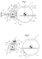
- the winding machine 1 shown in a schematic form in FIG. 1 comprises a support drum 2, also referred to as a pressing drum or back-up roller, which runs along an imaginary horizontal line G, shown in broken lines, by means of a pressing device 13, for example one shown, acting on both bearing journals of the supporting drum 2, not shown Piston unit or a spindle drive, is displaceable (double arrow 3) and driven by a drive, in the case shown by a center drive.
- a support drum 2 also referred to as a pressing drum or back-up roller, which runs along an imaginary horizontal line G, shown in broken lines, by means of a pressing device 13, for example one shown, acting on both bearing journals of the supporting drum 2, not shown Piston unit or a spindle drive, is displaceable (double arrow 3) and driven by a drive, in the case shown by a center drive.
- a support drum 2 also referred to as a pressing drum or back-up roller, which runs along an imaginary horizontal line G, shown in broken lines, by means of a pressing
- the material web 4 is either led out of a smoothing unit (not shown here) or also a drying section of a paper or board machine (also not shown here), then first wraps around a spreader roller (not shown) and then runs in the direction of the arrow on the lateral surface 5 of the carrying drum 2, wrapping around the lateral surface 5 of the support drum 2 by a certain angle (wrap area) until it is detached by the resulting winding roller 6.
- the detachment of the material web 4 from the support drum 2 and the transfer to the resulting winding roller 6 takes place in the winding gap 7, which occurs during the main winding phase between the support drum 2 and the winding roller 6 forms.
- the winding roll 6 is guided by means of a transport device, not shown, in the direction of movement indicated by the arrow 8.
- the transport device can be formed, for example, by a spindle drive which comprises a threaded spindle driven by an electric motor.
- the transport device serves to hold and guide the reel 10 of the winding roller 6 resting on the rails (guideway) 9.
- an empty reel (empty reel) 11 is held by a holding device (not shown) at a distance from the carrying drum 2 held ("standby position").
- the carrier drum 2 is displaced by the pressing device 13, which also regulates the line force L in the winding gap 7 by means of a control unit (not shown in more detail), that is to say the carrier drum 2 is pressed against the circumference of the winding roller 6 with a defined force, whereby an approximately desired winding hardness of the winding roll 6 or an approximately uniform winding hardness curve can be regulated.
- a control unit not shown in more detail
- the line force L can also be kept at, for example, a constant value if there is a major disturbance in the winding process that lasts for a longer time (seconds to minutes).
- the control unit can have a structure that is part of the known state of the art, with piezo quartzes integrated into the sliding surfaces of the support elements, for example, as sensors (measured value sensors). Of course, other types of sensors can also be used.
- Below the winding roll 6, the air squeezing device 12 is shown in dash-dotted form, which is in no active relationship with the winding roll 6 during the main winding phase shown. Rather, it is in a waiting position.
- the air squeezing device 12 can be moved with generally known mechanisms both essentially linearly, preferably horizontally and / or vertically, and essentially along a contour of a segment of a circle.
- the carrier drum 2 can be displaced by means of a pressing device 13, the carrier drum 2 is designed in the manner of a deflection adjusting roller 14, the roller jacket 15 of which is supported on a stationary yoke 17 by means of a number of supporting elements 16 arranged next to one another, and the course of the line force L in the winding gap 7 adjustable, preferably controllable, by moving the support drum 2 and / or at least one of the support elements 16.
- This configuration of the support drum 2 makes it possible, despite any unevenness in the surface contour of the winding roller 6 (short-wave fluctuations), to achieve precise adjustment, preferably regulation, of the course of the line force L between the support drum 2 and winding roller 6, and on the other hand, air pockets between the to prevent individual layers of the winding roller 6.
- the support elements 16 preferably act in the direction of the winding gap 7 which can be changed in its position, and the yoke 17 can be pivoted in such a way that the direction of action W of the support elements 16 follows the traveling movement of the winding gap 7 indicated by the arrow 18.
- the support elements 16 can be adjusted overall and / or in sections and / or in groups and / or individually, preferably adjustable.
- the adjustment, preferably regulation, of the support elements 16 is carried out by means of a hydraulic system, for example known from German published patent application DE 25 55 677 A1, including the associated control unit; their content is hereby made the subject of this description. Hydraulic systems of this type have proven to be suitable in other applications in a paper or board machine, for example in a shoe press.
- the hydraulic fluid used can be used as a lubricant for the sliding surfaces of the support elements 16.
- the winding machine 1 can either have two separate control units for the support drum 2, a first control unit for the displacement of the support drum and a second control unit for the movement of the support elements, or a common control unit with higher-quality intelligence to perform both functions.
- FIG. 2 shows a schematic side view of a winding machine 1 Carrier drum 2 according to the invention during the winding phase.
- the winding phase is cut through the material web 4 by means of known devices, preferably completely, but at least partially, and on the the support drum 2 with the formation of a winding nip 7 created empty drum ("Empty drum") 11 transferred.
- the winding roll 6 was already before the start Start-up phase by means of the transport device already described by the Carrier drum 2 with the dissolution of the nip 7 and with the formation of a free Train moved away.
- the air squeeze device 12 Before opening of the winding gap 7 between the carrier drum 2 and the winding roller 6, the air squeeze device 12 is applied to the winding roller 6. Immediately when an effective area B is formed between the winding roll 6 and the air squeezing device 12, the effective force K in the effective area B by a Relocation of the air squeeze device 12 regulated.
- Such a control loop belongs to the knowledge area of the average specialist and is for example in the already mentioned German published application DE 198 07 897 A1 (PR10678 DE) of the applicant for a carrier drum.
- the air squeezer 12 becomes the effective area B while maintaining the effective force K Winding roll 6 shifted. The shift will only end when the winding roll 6 has reached its end position (reel change position) horizontally.
- FIG. 3 shows a highly schematic side view of the carrying drum 2 according to the invention together with the row of supporting elements 16 and the yoke 17 arranged side by side.
- the support elements 16 have a support stroke H S of 150 to 400 mm, preferably 200 to 300 mm
- the yoke 17 has a yoke length L J of 500 to 800 mm, preferably 600 to 750 mm
- the carrying drum 2 has an inner diameter D I of 1,000 to 1,250 mm, preferably 1,100 to 1,200 mm, and an outer diameter D A of 1,300 to 1,500 mm, preferably 1,350 to 1,450 mm.
- the support elements 16 have a support width B S, not shown, of 25 to 500 mm, preferably of 50 to 250 mm.
Landscapes
- Winding Of Webs (AREA)
- Replacement Of Web Rolls (AREA)
Applications Claiming Priority (2)
| Application Number | Priority Date | Filing Date | Title |
|---|---|---|---|
| DE10030199A DE10030199A1 (de) | 2000-06-20 | 2000-06-20 | Verfahren und Wickelmaschine zum kontinuierlichen Aufwickeln einer Materialbahn |
| DE10030199 | 2000-06-20 |
Publications (2)
| Publication Number | Publication Date |
|---|---|
| EP1167256A2 true EP1167256A2 (fr) | 2002-01-02 |
| EP1167256A3 EP1167256A3 (fr) | 2003-12-10 |
Family
ID=7646275
Family Applications (1)
| Application Number | Title | Priority Date | Filing Date |
|---|---|---|---|
| EP01108104A Withdrawn EP1167256A3 (fr) | 2000-06-20 | 2001-03-30 | Méthode et enrouleuse pour enrouler en continue une bande de matériau |
Country Status (4)
| Country | Link |
|---|---|
| US (1) | US6604703B2 (fr) |
| EP (1) | EP1167256A3 (fr) |
| CA (1) | CA2351985A1 (fr) |
| DE (1) | DE10030199A1 (fr) |
Cited By (3)
| Publication number | Priority date | Publication date | Assignee | Title |
|---|---|---|---|---|
| WO2008065240A1 (fr) * | 2006-11-30 | 2008-06-05 | Metso Paper, Inc. | Procédé et dispositif dans un enrouleur de bande fibreuse |
| US7959102B2 (en) | 2007-10-12 | 2011-06-14 | Swiss Winding Performance Ag | Winder for a meterial web of flexible material |
| EP2481849A1 (fr) * | 2002-04-25 | 2012-08-01 | Voith Patent GmbH | Procédé de production d'une bande de papier |
Families Citing this family (10)
| Publication number | Priority date | Publication date | Assignee | Title |
|---|---|---|---|---|
| WO2003076320A1 (fr) * | 2002-03-08 | 2003-09-18 | Metso Paper Karlstad Ab | Installation et procede d'enroulement d'une bande de papier et dispositif de commande de la charge de contact |
| US7597778B2 (en) * | 2002-04-25 | 2009-10-06 | Voith Paper Patent Gmbh | Method for the production of a web of tissue material |
| DE10234958A1 (de) | 2002-07-31 | 2004-02-12 | Voith Paper Patent Gmbh | Verfahren zum Überführen eines Aufführstreifens einer Materialbahn auf eine Wickelvorrichtung |
| DE10326304A1 (de) * | 2003-06-11 | 2005-02-03 | Voith Fabrics Patent Gmbh | Verfahren und Vorrichtung zur Herstellung einer Tissuebahn |
| DE10342210A1 (de) * | 2003-09-12 | 2005-04-07 | Voith Paper Patent Gmbh | Verfahren und Vorrichtung zum Messen eines Bahnzugs einer Materialbahn und einer Nipkraft in einem Nip |
| US8032246B2 (en) * | 2007-02-02 | 2011-10-04 | Kimberly-Clark Worldwide, Inc. | Winding method for uniform properties |
| EP2298676A1 (fr) * | 2009-09-17 | 2011-03-23 | The Procter & Gamble Company | Dispositif pelable pour dévider une toile de matériau d'un rouleau |
| DE102010023921A1 (de) * | 2010-06-16 | 2011-12-22 | Kampf Schneid- Und Wickeltechnik Gmbh & Co. Kg | Wickelmaschine zur Herstellung von Wickelrollen aus Materialbahnen |
| CN108069274A (zh) * | 2018-01-03 | 2018-05-25 | 唐新雄 | 无纺布后加工收放卷系统 |
| DE102023135403A1 (de) * | 2023-12-15 | 2025-06-18 | Brückner Maschinenbau GmbH | Folienaufwickelvorrichtung, Folienherstellungsanlage sowie Verfahren zum Aufwickeln einer Folienbahn |
Family Cites Families (11)
| Publication number | Priority date | Publication date | Assignee | Title |
|---|---|---|---|---|
| CH604940A5 (fr) * | 1975-12-08 | 1978-09-15 | Escher Wyss Ag | |
| DE7609748U1 (de) * | 1976-03-30 | 1978-09-07 | Bruene, Bernhard, 5276 Wiehl | Wickelmaschine fuer folien |
| FI82432C (fi) * | 1988-02-22 | 1991-03-11 | Ahlstroem Valmet | Banrullningsanordning. |
| FI100099B (fi) * | 1988-11-17 | 1997-09-30 | Valmet Paper Machinery Inc | Menetelmä ja laite paperirainan rullauksessa |
| FI91383C (fi) * | 1990-10-26 | 1997-01-22 | Valmet Paper Machinery Inc | Menetelmä kiinnirullauksessa |
| US5308008A (en) * | 1992-03-18 | 1994-05-03 | Rueegg Anton | Method and apparatus for producing rolls |
| ATE290504T1 (de) * | 1997-01-25 | 2005-03-15 | Voith Paper Patent Gmbh | Wickelmaschine und verfahren zum kontinuierlichen aufwickeln einer materialbahn |
| ATE320996T1 (de) | 1997-05-16 | 2006-04-15 | Voith Paper Patent Gmbh | Verfahren und wickelmaschine zum kontinuierlichen aufwickeln einer materialbahn |
| US5931406A (en) * | 1997-12-08 | 1999-08-03 | Voith Sulzer Papiertechnik Patent Gmbh | Method and winder for the continuous winding of a material web |
| DE19807897A1 (de) * | 1998-02-25 | 1999-08-26 | Voith Sulzer Papiertech Patent | Verfahren und Vorrichtung zum kontinuierlichen Aufwickeln einer Materialbahn |
| DE19852257A1 (de) * | 1998-11-12 | 2000-05-18 | Voith Sulzer Papiertech Patent | Wickelmaschine zum Aufwickeln einer Materialbahn |
-
2000
- 2000-06-20 DE DE10030199A patent/DE10030199A1/de not_active Withdrawn
-
2001
- 2001-03-30 EP EP01108104A patent/EP1167256A3/fr not_active Withdrawn
- 2001-06-13 US US09/880,490 patent/US6604703B2/en not_active Expired - Fee Related
- 2001-06-19 CA CA002351985A patent/CA2351985A1/fr not_active Abandoned
Cited By (3)
| Publication number | Priority date | Publication date | Assignee | Title |
|---|---|---|---|---|
| EP2481849A1 (fr) * | 2002-04-25 | 2012-08-01 | Voith Patent GmbH | Procédé de production d'une bande de papier |
| WO2008065240A1 (fr) * | 2006-11-30 | 2008-06-05 | Metso Paper, Inc. | Procédé et dispositif dans un enrouleur de bande fibreuse |
| US7959102B2 (en) | 2007-10-12 | 2011-06-14 | Swiss Winding Performance Ag | Winder for a meterial web of flexible material |
Also Published As
| Publication number | Publication date |
|---|---|
| EP1167256A3 (fr) | 2003-12-10 |
| US6604703B2 (en) | 2003-08-12 |
| CA2351985A1 (fr) | 2001-12-20 |
| US20010052560A1 (en) | 2001-12-20 |
| DE10030199A1 (de) | 2002-01-03 |
Similar Documents
| Publication | Publication Date | Title |
|---|---|---|
| EP0912435B1 (fr) | Procede de bobinage continu d'une bande de materiau et bobineuse correspondante | |
| DE69620089T2 (de) | Wickelverfahren und Wickelmaschine | |
| DE68915705T2 (de) | Vorrichtung und Verfahren zum Aufwickeln einer Papierbahn. | |
| EP0941955B1 (fr) | Méthode et dispositif pour continuellement enrouler une bande de matériau | |
| DE69803049T2 (de) | Verfahren zum kalandrieren und ein kalander zur durchführung des verfahrens | |
| DE3201635C2 (de) | Kalanderanordnung | |
| EP0921085A2 (fr) | Procédé et machine d'enroulage pour enrouler en continu une bande de matière | |
| DE69116086T2 (de) | Aufwickeln und Verfahren zur Regelung des Kontaktdrucks während eines Aufwickelns | |
| DE10030199A1 (de) | Verfahren und Wickelmaschine zum kontinuierlichen Aufwickeln einer Materialbahn | |
| EP0959032B1 (fr) | Méthode et machine pour enrouler une bande de matériau | |
| DE69915339T2 (de) | Verfahren und vorrichtung zum kontrollieren der struktur einer rolle | |
| DE4343173A1 (de) | Kalander und nachgeschaltete Wickelvorrichtung | |
| EP1238933B1 (fr) | Méthode et dispositif pour continuellement enrouler une bande de matériau | |
| DE19939506A1 (de) | Verfahren und Wickelmaschine zum Aufwickeln einer Materialbahn | |
| DE19832067B4 (de) | Kalander für Bahnen aus Papier oder ähnlichem Material | |
| EP0972880B1 (fr) | Calandre pour bandes de papier ou analogue | |
| DE19832066C2 (de) | Kalander für Bahnen aus Papier oder ähnlichem Material | |
| DE10195949T5 (de) | Mehrspaltkalander und Kalanderaufbau | |
| WO2010149404A1 (fr) | Machine d'enroulement permettant d'enrouler de manière continue une bande de matière fibreuse | |
| EP1591390B1 (fr) | Bobineuse pour le bobinage continu d'une bande de matériau | |
| DE10023057A1 (de) | Wickelmaschine zum kontinuierlichen Aufwickeln einer Materialbahn | |
| EP1591391B1 (fr) | Bobineuse pour le bobinage continu d'une bande de matériau | |
| EP1414726B2 (fr) | Procede et bobineuse destines a l'enroulement continu d'une bande de materiau | |
| DE19748995A1 (de) | Verfahren und Wickelmaschine zum kontinuierlichen Aufwickeln einer Materialbahn | |
| DE19534911C2 (de) | Kalander für die Behandlung einer Papierbahn |
Legal Events
| Date | Code | Title | Description |
|---|---|---|---|
| PUAI | Public reference made under article 153(3) epc to a published international application that has entered the european phase |
Free format text: ORIGINAL CODE: 0009012 |
|
| AK | Designated contracting states |
Kind code of ref document: A2 Designated state(s): AT BE CH CY DE DK ES FI FR GB GR IE IT LI LU MC NL PT SE TR |
|
| AX | Request for extension of the european patent |
Free format text: AL;LT;LV;MK;RO;SI |
|
| PUAL | Search report despatched |
Free format text: ORIGINAL CODE: 0009013 |
|
| RIC1 | Information provided on ipc code assigned before grant |
Ipc: 7B 65H 18/26 A |
|
| AK | Designated contracting states |
Kind code of ref document: A3 Designated state(s): AT BE CH CY DE DK ES FI FR GB GR IE IT LI LU MC NL PT SE TR |
|
| AX | Request for extension of the european patent |
Extension state: AL LT LV MK RO SI |
|
| 17P | Request for examination filed |
Effective date: 20040611 |
|
| AKX | Designation fees paid |
Designated state(s): AT DE FI SE |
|
| 17Q | First examination report despatched |
Effective date: 20050307 |
|
| STAA | Information on the status of an ep patent application or granted ep patent |
Free format text: STATUS: THE APPLICATION IS DEEMED TO BE WITHDRAWN |
|
| 18D | Application deemed to be withdrawn |
Effective date: 20050719 |