EP1167590A2 - Mesure de la longeur de fibres - Google Patents
Mesure de la longeur de fibres Download PDFInfo
- Publication number
- EP1167590A2 EP1167590A2 EP01114142A EP01114142A EP1167590A2 EP 1167590 A2 EP1167590 A2 EP 1167590A2 EP 01114142 A EP01114142 A EP 01114142A EP 01114142 A EP01114142 A EP 01114142A EP 1167590 A2 EP1167590 A2 EP 1167590A2
- Authority
- EP
- European Patent Office
- Prior art keywords
- nits
- card
- stack
- actuator
- machine
- Prior art date
- Legal status (The legal status is an assumption and is not a legal conclusion. Google has not performed a legal analysis and makes no representation as to the accuracy of the status listed.)
- Withdrawn
Links
Images



Classifications
-
- D—TEXTILES; PAPER
- D01—NATURAL OR MAN-MADE THREADS OR FIBRES; SPINNING
- D01G—PRELIMINARY TREATMENT OF FIBRES, e.g. FOR SPINNING
- D01G31/00—Warning or safety devices, e.g. automatic fault detectors, stop motions
- D01G31/006—On-line measurement and recording of process and product parameters
Definitions
- the present invention is concerned with the application of fiber length measurement in the Blowroom or carding mill of a spinning mill.
- the conventional blow room lines and in the subsequent carding is often the same textile fibers over longer periods of time, e.g. Cotton, man-made fibers, or mixtures thereof (assortments) processed.
- the Settings of the textile processing machines are usually based on the corresponding Material types adjusted or optimized only once and then no longer changed. Such operating parameter settings are usually cumbersome and require relatively much time.
- the production line may require fiber material samples at various points remove and some of these with complex and time-consuming measuring methods analyze in the laboratory (e.g. measurement of the staple fiber shortening, number of nits, Short fiber content).
- DE-A-196-51-893 describes a method and a device in which the staple fiber length and the number of nits are measured on a card. The measured values determined are used to set the operating parameters of the card. To optimize production, the number of nits and the fiber length distribution are determined and linked. Based on this link, a regulation or control specifies the optimal operating parameters. The measurement is carried out online (measurement of the stack diagram and number of nits). The following two operating parameters (manipulated variables) are adjusted: the distance between the sets of covers and the drum (carding gap) and the speed of the drum. The optimal setting values are regulated or determined on the basis of stored characteristic diagrams / characteristic curves which also contain the associated machine setting data.
- the input data are compared with these maps / characteristic curves.
- the fiber samples required for evaluation are suctioned off.
- extraction can take place at the following locations: on the customer, on the doctor roller, on the squeeze rollers, or on the licker-in.
- the stack which can be measured online, is measured using a fibrograph (fiber beard curve).
- fibrograph fiber beard curve
- a method and a device is further described in which the fiber stack is measured twice. At the entrance and at the exit of the card, partial quantities of the fibers are removed, for example by suction.
- the fiber reduction amount is determined from the difference values of the measurements. Depending on the value, those working elements that influence the carding gap are readjusted or optimized (influencing the carding intensity).
- Fiber samples are taken at the following locations: on the customer, on the doctor roll, before or after the squeeze rolls, on the reel or on the licker-in.
- the samples are evaluated automatically and online, ie the stack diagram is determined from the values.
- the evaluations serve as input data for the regulating and control devices, which determine the optimal machine setting data.
- the optimal machine setting data with regard to the carding gap are passed on online to those working elements or actuators of the carding machine which control the distance between the clothing of the drum and the cover.
- the control and regulating devices have stored characteristic curves.
- a fibrograph and a fiber shortening sensor are provided for fiber length measurement.
- the invention is based on the object of a method and a device to create which, among other things, essentially the above Disadvantages eliminated and the fiber processing both in the carding, as in the Blow room further improved.
- the problem is solved by the characterizing features of the claims.
- the inventive method and its device make it possible to Optimal control of fiber or flake processing. That means the fibers or the Flakes are processed as optimally as possible, while observing one if possible little fiber damage (fiber shortening) or nits. Additionally allowed the inventive method and its device a fast and automatic Adaptation of fiber processing to fluctuations in fiber material quality (Variations caused by different material quality or properties of the individual fiber bales) and generally on new fiber materials to be processed (i.e. acceleration of the setting of the machines to new ones to be processed Assortments).
- the invention provides a method and a device on a textile processing machine, in particular on a blow room machine, card or card, in which the number of nits and / or the fiber length (stack) is measured and evaluated before and / or after a working element.
- a nit sensor and a fiber length measuring device are provided accordingly and carry out the measurements (the fiber length measuring device taking a small amount of fiber as a sample).
- a regulation / control is provided, which receives the named measured values for fiber length and / or number of nits from the sensors as input variables and determines optimized machine setting data therefrom.
- the regulation / control preferably works with stored characteristic maps or data records.
- the determined machine setting data or parameters are output to one or more actuators influencing the number of nits and / or the fiber stack of the textile processing machine.
- actuators can be controlled or regulated in combination in order to change one or more settings on the machine.
- the measurements are carried out on a working element, while the actuators affected belong to other upstream or downstream working elements; in particular, this also includes actuators of other textile processing machines.
- this regulation or control can take place online and automatically, ie during operation, without external intervention by the operating personnel.
- the actuators mentioned change at least one of the following settings: the clamping distance between the feed trough and the licker-in, or their clamping force, the licker-in speed or speeds (in the case of several licker-ins ), the transmission factor (which can be changed by individual actuators or a combination of the latter), the production of a single working element or the entire textile processing machine (in the case of the card or card, this means in particular the run-out speed of the fiber sliver or the sliver weight), as well as the angular position and the distance of the scraper or discharge knives.
- blow room machines In addition to the features mentioned above, it is particularly important for the application of the invention to blow room machines that the actuators change at least one of the following settings: the speed of the cleaning or opening rollers, the grate position or angle, position or angle of the stripping or Elimination knife, clamping distance or clamping force of the feed roller to the feed trough in front of the respective cleaning or opening rollers.
- blow room machines are to be understood in particular as bale openers, fine or coarse cleaners, mixers and filling shafts, or more generally, all textile processing machines of the blow room upstream of the carding machine.
- the inventive concept therefore includes the following devices, methods and uses: A method on a card or card, in which the number of nits and / or the fiber length (stack) is determined before and / or after a working element, a regulation / control being provided which uses the values mentioned for the fiber length and / or number of nits as input variables receives and determines optimized machine setting data therefrom and outputs this to at least one actuator of a working element influencing the number of nits and / or the stack of card or card, at least one actuator the distance between feed roller and licker-in and / or the clamping distance and / or the clamping force of the feed trough changed at the licker.
- the feed device, the licker-in, the carding segments in the different carding zones e.g. the pre- and post-carding zone, fixed or revolving carding carding zone
- the reel spool e.g. the taker-off, the knives, the removal device, the infeed and to understand the outlet regulating devices of textile processing machines, or entire textile processing machines as such (for example a card or a card).
- the determination of the fiber length or stack and the number of nits is done by special measuring devices and sensors, which preferably allow online evaluation. Such devices are known from the prior art and are subject to constant further development. These measuring devices are not discussed in the following because they are also not the subject of the invention.
- clamping distance is understood to mean the distance between the clamping point of the feed trough feed roller (ie the outermost or narrowest nip between the trough and the feed roller at the trough outlet) and the first licker-in.
- clamping force can be viewed as the force or pressure that acts between the feed trough and the feed roller.
- a method on a card or card in which the number of nits and / or the length of the fibers (stacks) is determined before and / or after a working element, a regulation / control being provided which has the stated values for the length of the fibers and / or number of nits receives as input variables and determines optimized machine setting data therefrom and outputs them to at least one actuator influencing the number of nits and / or the stack of the card or card, at least one of the named actuators changing the licker-in speed or licker-in speed, or the actuator is a means which is the transmission factor changed, or that at least one of the actuators mentioned changes the production of the card, in particular the outfeed speed or the strip weight.
- a conventional belt drive can be used to change the speed of the licker-in (s), but the use of a frequency converter is preferred.
- the term "transmission factor indicates what percentage of the fiber mass on the reel is transferred to the customer with each revolution of the reel.
- a transmission factor of 20% means, for example, that 20% of the fibers on the reel change to the customer per revolution. In other words, each fiber runs an average of five times with the drum (and is carded) before it is picked up by the customer.
- the inventive concept also includes the possibility that the actuator which changes the transmission factor can consist of several means Throughout the patent specification, the term “actuator” is also to be understood as meaning several means.
- an actuator can include several (mechanical) adjustment mechanisms with the associated motors and possibly the associated frequency converters or electronic controls.
- the inventive concept also includes the fact that the transfer factor depends on several settings / parameters and can therefore also be influenced by several actuators.
- several actuators can be involved at the same time, e.g. actuators that change the spacing between licker-in or drum-take-off, or actuators that can adjust the speed of the drum or take-off (or the ratio of the speed of the drum to the speed of the customer) ).
- the transmission factor is also influenced by other factors. This includes in particular the type of fiber, the set production and the type of card clothing, as well as their sharpness.
- further actuators can be used for all these factors.
- a sensor can determine the sharpness of the sets and an actuator according to the invention can improve the sharpness of the sets.
- the actuator can thus also represent a grinding device or generally be another maintenance element.
- Such grinding devices or maintenance elements are described in further patent documents of the applicant.
- the production of the card ie fiber mass delivered per unit of time per sliver
- the sliver weight ie the weight per unit length of the card sliver
- the speed of the card sliver is in turn directly proportional to the circulation speed of the customer (although it can be assumed that the transfer factor remains unchanged).
- the customer is powered by its own motor.
- the customer can also be driven by the main drive motor via a belt drive.
- the ratio of the drum and taker speeds remains constant if the transfer factor is to remain unchanged, and the outfeed speed is determined by the card's main drive.
- the outfeed speed is determined by the card's main drive.
- the production is equal to the outlet speed x belt weight and the belt weight should not be changed, the production is determined solely by the outlet speed and thus by the circulation speed of the customer.
- the sliver weight itself is determined by the weight of the wadding and the basic warpage, the ratio of the peripheral speed of the customer to that of the feed roller (ie sliver weight equals wadding weight multiplied by the effective warpage in the card).
- the speed of the feed roller is thus also indirectly determined by the peripheral speed of the customer.
- Small variations in the wad weight of the wadding template fed to the card feeding device are attempted to be compensated for with small changes in the feed roller speed (change in the basic warping).
- Short-term fluctuations in the weight of the cotton wool in front of or in the feed device of a card are recognized by a corresponding measuring device, whereupon the speed of the feed rollers is adjusted accordingly via a control system (including actuators).
- This regulation / control is referred to in the prior art as short-term correction.
- a so-called long-term correction is usually also provided.
- the long-term correction has the purpose, as mentioned above, of keeping the strip weight at a constant value.
- the belt weight is usually measured at the output of the card and the peripheral speed of the feed roller is adjusted accordingly (ie the effective warpage is regulated). This ensures that long-term deviations in the belt weight can be corrected.
- the long-term correction is usually supplemented by the short-term correction.
- the speeds of the rotating work elements must adapt to the sliver's outfeed speed.
- frequency converters or equivalent gear ratios are used as actuators, which control the speed of the drive motors.
- the actuators can in turn be controlled via associated control units. These control units can carry out their own evaluation and can be connected both to the corresponding measuring devices and to central control units, which regulate and control the processes and production in the entire blow room and card shop. It would of course also be conceivable, if not usually sensible, to influence the production of the card by means of actuators which change the strip weight.
- the method according to the invention also includes the possibility of optimizing the Machine setting data on at least one of the nits and / or the Stack influencing actuator of an upstream or downstream textile fiber processing machine output, in particular to an actuator of an upstream blowroom machine like on an actuator of a filling shaft upstream of the card or card (Influencing the wadding by the filling shaft).
- actuator also includes related resources.
- the invention generally also encompasses the idea of a method on a blowroom machine for processing textile fibers to provide that before and / or after one or several working elements of the blowroom machine the number of nits and / or the fiber length (Stack) is determined and optimized machine setting data is determined from it become.
- a regulation / control can be provided for this, which the mentioned Receives values for fiber length and / or number of nits as input values and from them optimized machine setting data determined. This can be done using the optimized machine setting data at least one influencing the number of nits and / or the stack Actuator of the blowroom are output, in particular to an actuator of the same blowroom machine or an upstream or downstream textile fiber processing machine.
- blowroom machine also includes the possibility that at least one of the actuators mentioned changes the speed of the cleaning or opening roller, or that at least one of the actuators changes the grate position or grate angle, or that at least one of the actuators mentioned changes the clamping distance and / or the clamping force of the feed trough to the cleaning or opening roller is changed.
- the definitions of the clamping distance and the clamping force on these machines are analogous to those of the carding device explained earlier.
- the term "blowroom machine” can be understood to mean a cleaner, in particular a fine or a coarse cleaner, or a bale opener.
- the regulation / control the optimized machine setting data based on specified or stored maps or data records can be determined.
- the enumerated methods according to the invention in a textile fiber processing plant can also be used in combination. Which is also why Combinations of the individual methods according to the invention claimed for the applicant become.
- the methods described also include the corresponding devices:
- a device in a textile fiber processing machine in particular a card, card, in which the number of nits and / or the length of the fibers (stacks) is determined before and / or after at least one working element, with a regulation / control being provided which is carried out according to a method described above receives the stated values for fiber length and / or number of nits as input variables and uses them to determine optimized machine setting data and outputs them to at least one actuator influencing the number of nits and / or fiber length (stack), the actuator (s) affected changing at least one of the following operating parameters: the Clamping distance and / or the clamping force of the feed trough on the licker-in, one or more licker-in speeds, the transfer factor, the production of the card, in particular the run-out speed or the belt weight, the distance or the angular position of the doctor blades.
- a blowroom machine for processing of textile fibers (especially for bale openers, fine or coarse cleaners, or Filling chutes) is provided that before and / or after at least one working element the blowroom machine determines the number of nits and / or the fiber length (stack) optimized machine setting data is determined.
- a regulation / control can be provided on the device, which values for fiber length and / or number of nits according to a method described above received as input variables and determined optimized machine setting data from them.
- a device can be equipped in such a way that that the optimized machine setting data on at least one of the nits and / or the actuator influencing the fiber length (stack) are output, in particular to an actuator of the same blowroom machine or an upstream or downstream one Textile fiber processing machine, which at least one of the following Operating parameters changed: The speed of the cleaning or opening roller, the Grate position or angle, the clamping distance and / or the clamping force of the feed trough for cleaning or opening roller.
- Figure 1 shows schematically the fiber flow through a work element of the carding machine or blow room.
- work element both entire textile processing machines, such as cards, cards, cleaners in the blow room, etc. be understood as well as individual elements of a textile processing machine, For example, beaters, feeders, carding segments (stationary or in Revolving cover), drum, maintenance elements, buyers, outlet regulations, separating or scraper blades, grate bars, opener and feed rollers, exhaust air and suction systems etc.
- the measuring devices which before and after the work element connected to the textile fiber flow can measure properties of the textile fibers. These can be single or multiple properties, especially the fiber or the staple fiber length (single fiber measurement is preferred) or the number of nits.
- the measuring devices are only shown schematically, i.e. the devices can also comprise several sensors, which simultaneously have several fiber properties measure up.
- the measuring technology used does not really play a role in the invention Role.
- the measuring device optically reflects the fiber properties determined or small fiber samples taken from the fiber flow for measurement.
- the Measurement results are then from the measuring devices of an evaluation system transmitted.
- This evaluation system is capable of optimized setting values or parameters of the work element. This can, for example, be saved Records or maps happen. Under certain circumstances, this evaluation system connected to other similar evaluation systems. This is before An advantage wherever there are interactions with other work elements can, e.g. for working elements of the same textile processing machine.
- the evaluation systems with a central control unit connected, which controls the production of the entire blow room and card shop.
- the central control unit can influence the evaluation systems own, or on their output signals.
- the evaluation systems can send signals to individual or multiple control units connected to actuators are. Under certain circumstances, these actuators can even become upstream or downstream work elements belong.
- the actuators influence the processing of the fibers in the working element.
- the "actuators" can use several means exist, e.g. from gear and drive motor.
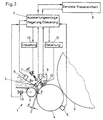
- FIG. 2 shows a possible application of the device according to the invention or Procedure shown on the feeding device of a card.
- the conventional feeding device 1 leads over a feed roller 2 and a swiveling or adjustable feed trough 3 the fiber material to a licker-in 4. from there the fiber material is attached the drum 5 passed to the card.
- Measuring devices 6 are provided at two points, from which fiber samples are taken and be analyzed.
- the measuring devices themselves are not the subject of the invention. As shown in FIG. 2, they can consist of individual units or from a central measuring device, which take fiber samples at several points can.
- the measuring device can measure individual or multiple fiber properties.
- a measuring device could consist of a combination of sensors which can measure the fiber length (pile) and the number of nits.
- the two measuring devices 6 pass the determined fiber properties to an evaluation system 7 further.
- the evaluation system 7 is able to use the parameters obtained optimal operating parameters of individual or multiple work elements determine. It therefore takes over the local regulation and control of these work elements. It is also conceivable that the individual measuring devices 6 in the evaluation system 7 are integrated.
- the evaluation system 7 is in this example also in connection with a central control unit 8, which is the evaluation system and can influence their output signals. In this central control unit 8 it can be the central control unit of the entire blow room or carding system act or just the central control unit of the respective machine.
- the central one Control unit 8 can be connected to several such evaluation systems 7 stand and coordinate the interaction (not shown in the figure).
- the evaluation system 7 also registers the clamping force in this example via a sensor 8a F the feed trough on the feed roller, as well as the clamping distance d over one Sensor 9.
- the evaluation system 7 determines on the basis of the input values mentioned the optimal operating parameters, in this example the clamping distance d, the clamping force F and the distance between feed roller and licker-in.
- the signals corresponding to the optimal operating parameters to the controls 10 of the actuators 11 and 12, or directly to the actuator 13 (Actuators shown schematically).
- the controllers 10 register the input signal and set the actuators 11 and 12 to the correct values.
- the Actuator 11 is used to set the clamping force F, while actuator 12 is the clamping distance d can change.
- the distance between feed roller and licker is from the evaluation system 7 controlled directly via the actuator 13.
- the exact technical Interaction between the evaluation system, control and actuators is for the invention not essential.
- the presence of a central control unit is also important for the invention is not absolutely necessary. It is important that the evaluation system corresponding machine setting data and then to the corresponding Passes on actuators that affect the number of nits and / or the stack of the machine.
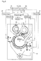
- Figure 3 is largely identical to Figure 2, it was only by another Application of the device according to the invention supplemented.
- the expansion includes in the example according to FIG. 3, a further evaluation system 14.
- This evaluation system 14 is connected on the one hand to the same measuring device 6 on the licker-in 4 as that Evaluation system 7. It receives the same measured values from it. On the other hand, it is Evaluation system 14 connected to a second measuring device 15 on the drum 5.
- the evaluation systems 14 and 7 are also connected to one another. she exchange data with each other and can therefore interact with each other.
- the evaluation system 14 optimizes via a controller 16 (e.g. a frequency converter) and an actuator 17 (drive) the speed of the licker-in 4.
- a controller 16 e.g. a frequency converter
- actuator 17 drive
- the evaluation system 14 is the speed of the licker-in 4 also adapt on the basis of those signals which they receive from the Evaluation system 7 receives.
- the two evaluation systems are 7 and 14 coupled to each other, but only the evaluation system 7 is connected to the central one Control unit 8 connected.
- the individual evaluation systems are not directly connected to one another are all in communication with each other via the central control unit 8 stand.
- the central control unit can be used in the optimization process of the individual evaluation systems intervene and influence it. The task of the central control unit it is to coordinate the whole system or to coordinate the evaluation systems. According to FIG.
- the evaluation system 14 is also able to use a further control 18 (e.g. further frequency converter) and an actuator 19 (e.g. electric motor), adjust the speed of the drum 5.
- a further control 18 e.g. further frequency converter
- an actuator 19 e.g. electric motor
- This adjustment can on the one hand optimization of the operating parameters apply.
- the change can also just a simple production adjustment.
- the evaluation system 14 directly or indirectly (as shown in Figure 3) with the central control unit be connected.
- the central control unit can therefore not only interact coordinate the individual evaluation systems (e.g. specify processing quality), but can also control production.
- FIG. 4 shows a further application of the invention to a card or card, in which primarily the transmission factor is optimized.
- An evaluation system 20 is connected via a plurality of controls 21 to the actuators 22, which are the Control the speeds of the licker-in 4, the drum 5 and the doffer 23.
- the Evaluation system 20 can also via the controller 24 and the actuator 25 (only shown schematically) adjust the distance between the pickup 23 and drum 5.
- Such a device can also be provided with regard to the licker-in be (not shown for the sake of clarity), i.e. one controller and one or more Actuators allow the distance between licker-in 4 and drum 5 to be set.
- a further control 26 is provided, which is actuated 27 (also only schematically shown) can adjust the position of the fiber-air guide element 28.
- the controlled ones Work elements all have an influence on the transmission factor.
- the Evaluation system 20 controls the setting of these work elements, so that an optimal one Influence on the transmission factor is generated.
- the evaluation system 20 is here also with the central control unit 8 and with a plurality of measuring devices 29 connected, which can determine the number of nits and / or the fiber length. Since the Production of the machine (processed amount of fibers per unit of time) has an impact the transmission factor also influences the production specification of the central Control unit 8 the transmission factor. The evaluation system 20 can if necessary compensate for this influence by adapting the work elements accordingly.
- the sensors 29 also allow constant control of the fiber processing and this enables targeted intervention by the evaluation system in the event of changes in processing quality of the working elements.
- FIG. 5 shows a further possibility of applying the invention.
- the example largely corresponds to FIG. 4, only that the evaluation system 20 is connected to the outlet device 30.
- the outlet device 30 regulates the sliver outlet or the sliver weight of the sliver at the outlet of the card or card using the built-in drafting device 30a.
- the outlet device 30 is only shown schematically in FIG. 5 because it is also not the subject of the invention.
- the drafting device 30a can also be arranged on the belt deposit.
- the evaluation system 20 also receives measured values from the outlet device 30 (for example the strip weight or the CV value). Corresponding controls and measuring devices are considered here as part of the outlet device 30 and were therefore not shown in FIG. 5.
- the outlet device 30 is directly connected to the central control unit 8 and not, as shown in FIG. 5, via the evaluation system 20.
- the evaluation system 20 and the central control unit 8 are also connected directly to a further evaluation system 31 ,
- the evaluation system 31 controls and regulates, via the schematically illustrated connections, 32 working elements which are upstream of the card or card shown.
- the evaluation system 31 can also belong to an upstream blowroom machine (for example an opener, a cleaner, a coarse cleaner, a fine cleaner, a deduster, a mixer) or to a filling shaft (which may be equipped with additional opening or cleaning elements).
- the evaluation system 31 controls one or more working elements of the associated textile processing machine (via actuators, not shown).
- the evaluation system 31 is connected upstream of the evaluation system 20.
- actuators can also be influenced by downstream textile processing machines.
- the evaluation system 31 could therefore just as well be connected downstream of the evaluation system 20 and influence corresponding working elements of downstream textile processing machines.
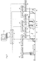
- FIG. 6 shows the application of the invention to a blowroom machine.
- the blowroom machine 33 is a fine cleaner
- the textile processing machine could in Figure 6 represent a coarse cleaner as well, or one another machine in the blow room.
- the principle of the invention is basically on all blowroom machines applicable (e.g. also on openers, filling shafts, dedusting machines and mixer) and is therefore also used for these areas of application.
- An evaluation system 34 also undertakes the optimization in the blowroom machine 33 the operating parameters. Via the lines 35, the system 34 can carry data with or downstream evaluation systems, as well as with a (not shown) central Replace control unit and be influenced by it. Through these connections the evaluation system 34 becomes part of a network for optimizing the Fiber processing.
- the evaluation system receives measured values from measuring devices 36, which are before and after one or (as shown here) several work items can be located.
- the various evaluation systems of a system can also use measuring devices together.
- the evaluation system 34 evaluates the measured values received from the devices 36 and those from the lines 35 received signals together. This can be due to maps, data records, or other methods happen.
- the determined, optimal Machine setting data or values via controls 37, 38 on actuators 39 transmitted, which set the work elements accordingly.
- the actuators mentioned 39 can, for example, the clamping distance on the blowroom machine shown and clamping force of the feed trough 43 change the speed of the feed roller 41, the Speed of the cleaning or opening roller 42, the grate position (grate angle) of the Rostes 40.
- the definitions of the terms "clamping distance” and "clamping force” became wider already done in the front, they are to be used analogously (opening roller 42 instead of one Licker).
- the blowroom includes in Different processing stages in the example shown: I. The opening, II. the Coarse cleaning, III. mixing, IV. fine cleaning, V intensive cleaning or - opening, and VI. carding.
- Each of these processing stages has at least one Textile processing machine which contains one or more evaluation systems 43.
- the evaluation systems 43 each evaluate the data they receive from measuring devices on the textile processing machines (not shown) or from before or downstream evaluation systems. The evaluation is also carried out by the Signals of the central control unit 8 influenced.
- the evaluation systems 43 Control the evaluation systems 43 and regulate the associated work elements on the basis of the input values obtained (only shown schematically via the connecting lines) and set the optimal machine settings on.
- the evaluation systems 43 are linked to one another. This on the one hand, to the respective machine settings or processing intensity of the Coordinate fibers. On the other hand, by measured values (fiber length or number of nits) of to receive upstream or downstream measuring devices.
- the evaluation systems are also connected to the central control unit 8. This has primarily Task to control and coordinate the entire system of evaluation systems. It can also specify the parameters to be observed for each evaluation system or influence them for the optimization of the entire blowroom line. In the second It can also reduce the production (amount of fiber to be processed per unit of time) control the whole line.
- the central control unit can use a monitoring system 44 communicate with the plant operators.
- the operator can be the specifications for fiber processing of the entire system or individual machines Enter 44 via the monitoring system.
- This system can be used by the operating personnel also on adjustments to the operating parameters or on quality fluctuations draw attention to the processed fiber material.
- the monitoring system 44 also with other data and information systems to link or integrate this into it.
- the data and Information system called "SPIDERweb" by the applicant.
- the inventive idea can be implemented particularly well if the in the figures described processes take place "online". That means the measurements, evaluations and controls take place continuously during operation.
- the goal is one if possible short reaction time between the occurrence of a change in the fiber flow (or Fiber property) and the appropriate influencing of the work element or elements receive.
- An important factor here is the performance of the measuring devices: The faster they can measure and evaluate a fiber property, the shorter is the total response time of the system.
Landscapes
- Engineering & Computer Science (AREA)
- Textile Engineering (AREA)
- Preliminary Treatment Of Fibers (AREA)
Applications Claiming Priority (2)
| Application Number | Priority Date | Filing Date | Title |
|---|---|---|---|
| CH12432000 | 2000-06-23 | ||
| CH12432000 | 2000-06-23 |
Publications (2)
| Publication Number | Publication Date |
|---|---|
| EP1167590A2 true EP1167590A2 (fr) | 2002-01-02 |
| EP1167590A3 EP1167590A3 (fr) | 2002-09-11 |
Family
ID=4564733
Family Applications (1)
| Application Number | Title | Priority Date | Filing Date |
|---|---|---|---|
| EP01114142A Withdrawn EP1167590A3 (fr) | 2000-06-23 | 2001-06-11 | Mesure de la longeur de fibres |
Country Status (2)
| Country | Link |
|---|---|
| US (1) | US6611994B2 (fr) |
| EP (1) | EP1167590A3 (fr) |
Cited By (2)
| Publication number | Priority date | Publication date | Assignee | Title |
|---|---|---|---|---|
| DE102006002390A1 (de) * | 2006-01-17 | 2007-07-19 | Maschinenfabrik Rieter Ag | Einstellvorrichtung für eine Textilmaterial verarbeitende Maschine |
| CN112105766A (zh) * | 2018-05-18 | 2020-12-18 | 特吕茨施勒有限及两合公司 | 用于确定梳理机上的锡林占用量的方法以及具有相关的控制装置的梳理机 |
Families Citing this family (14)
| Publication number | Priority date | Publication date | Assignee | Title |
|---|---|---|---|---|
| DE10233011B4 (de) * | 2002-07-20 | 2020-03-19 | Trützschler GmbH & Co Kommanditgesellschaft | Vorrichtung an einer Spinnereimaschine zur Erfassung und Beurteilung von Textilfasermaterial |
| DE10311345A1 (de) * | 2003-03-14 | 2004-09-23 | Trützschler GmbH & Co KG | Vorrichtung zur Ermittlung der Faserlängen und der Faserlängenverteilung an einer Fasermaterialprobe, insbesondere in der Spinnereivorbereitung |
| DK1633912T3 (da) * | 2003-05-28 | 2014-10-06 | Oerlikon Textile Gmbh & Co Kg | En fremgangsmåde og en fiberfordeler til at tørlægge fibre |
| DE102004055310A1 (de) * | 2004-11-16 | 2006-05-18 | Trützschler GmbH & Co KG | Vorrichtung an einer Spinnereimaschine, insbesondere Karde, Krempel, Reiniger o. dgl. zum Aufziehen einer Garnitur auf eine Walze |
| DE102008004098A1 (de) * | 2007-06-29 | 2009-01-02 | TRüTZSCHLER GMBH & CO. KG | Vorrichtung zur Fasersortierung bzw. -selektion eines Faserverbandes aus Textilfasern, insbesondere zum Kämmen, der über Zuführmittel einer Fasersortiereinrichtung, insbesondere Kämmeinrichtung zugeführt wird |
| CH703154B1 (de) * | 2007-06-29 | 2011-11-30 | Truetzschler Gmbh & Co Kg | Vorrichtung zur Fasersortierung bzw. -selektion eines Faserverbandes aus Textilfasern. |
| ITMI20081097A1 (it) * | 2007-06-29 | 2008-12-30 | Truetzschler Gmbh & Co Kg | Apparecchiatura per la cernita di fibre o la selezione di fibre di un fascio di fibre comprendente fibre tessili, specialmente per la pettinatura |
| CH703786B1 (de) * | 2007-06-29 | 2012-03-30 | Truetzschler Gmbh & Co Kg | Vorrichtung zur Fasersortierung bzw. -selektion eines Faserverbandes aus Textilfasern. |
| GB0811207D0 (en) * | 2007-06-29 | 2008-07-23 | Truetzschler Gmbh & Co Kg | Apparatus for the fibre-sorting or fibre-selection of a fibre bundle comprising textile fibres, especially for combing |
| CH704224B1 (de) * | 2007-06-29 | 2012-06-15 | Truetzschler Gmbh & Co Kg | Vorrichtung zur Sortierung bzw. Selektion von Fasern eines Faserverbandes aus Textilfasern. |
| GB0811191D0 (en) * | 2007-06-29 | 2008-07-23 | Truetzschler Gmbh & Co Kg | Apparatus for the fibre-sorting or fibre-selection of a fibre bundle comprising textille fibre, especially for combing |
| US8120769B2 (en) * | 2007-08-03 | 2012-02-21 | North Carolina State University | Method and system for fiber properties measurement |
| ITUB20155249A1 (it) * | 2015-10-30 | 2017-04-30 | Mesdan Spa | Dispositivo di misurazione per la misurazione dell?appiccicosita?, di imperfezioni e impurita? di fibre tessili, in particolare fibre di cotone. |
| CN118547408A (zh) * | 2019-01-31 | 2024-08-27 | 乌斯特技术股份公司 | 针对异物优化纺纱过程 |
Family Cites Families (13)
| Publication number | Priority date | Publication date | Assignee | Title |
|---|---|---|---|---|
| CH589731A5 (fr) * | 1974-11-01 | 1977-07-15 | Rieter Ag Maschf | |
| CH629544A5 (de) * | 1978-04-25 | 1982-04-30 | Rieter Ag Maschf | Verfahren zur steuerung der arbeitsverhaeltnisse in einer verarbeitungsmaschine der stapelfaserspinnerei und vorrichtung zur durchfuehrung des verfahrens. |
| CH627498A5 (de) | 1978-04-26 | 1982-01-15 | Zellweger Uster Ag | Verfahren und vorrichtung zur ausregulierung von bandgewichtsschwankungen an karden, krempeln und strecken. |
| DE2830367C2 (de) * | 1978-07-11 | 1985-03-28 | Hergeth KG Maschinenfabrik und Apparatebau, 4408 Dülmen | Verfahren und Vorrichtung zum Herstellen eines Wirrfaservlieses aus Spinngut, z.B. Wolle, Baumwolle, Chemiefasern u.dgl., mittels eines Krempelvorganges |
| US4275483A (en) * | 1979-12-05 | 1981-06-30 | Roberson James H | Control apparatus for a carding machine |
| CH640890A5 (de) * | 1980-01-17 | 1984-01-31 | Zellweger Uster Ag | Verfahren und vorrichtung zur regulierung von bandgewichtsschwankungen an karden und krempeln. |
| DE8607052U1 (de) * | 1986-03-14 | 1999-03-04 | Trützschler GmbH & Co KG, 41199 Mönchengladbach | Vorrichtung bei einer Karde, Krempel o.dgl. zur Vergleichmäßigung des Faserbandes oder -vlieses |
| DE3821238A1 (de) * | 1988-06-23 | 1989-12-28 | Rieter Ag Maschf | Verfahren und vorrichtung zur herstellung eines gleichmaessigen faserbandes |
| DE3913997A1 (de) | 1989-02-14 | 1990-08-23 | Rieter Ag Maschf | Dosierverfahren und -vorrichtung zur abgabe vorgebbarer mengen von faserflocken |
| EP0452676B1 (fr) * | 1990-03-22 | 1998-12-16 | Maschinenfabrik Rieter Ag | Champ d'identification de nettoyage |
| DE59108422D1 (de) * | 1990-11-14 | 1997-01-30 | Rieter Ag Maschf | Verfahren und Vorrichtung zur Steuerung einer Karde |
| DE19651891B4 (de) * | 1996-12-13 | 2006-10-05 | TRüTZSCHLER GMBH & CO. KG | Verfahren und Vorrichtung an einer Karde, Krempel o. dgl. zur Verarbeitung von Textilfasern, z. B. Baumwolle, Chemiefasern o. dgl. |
| DE19651893B4 (de) * | 1996-12-13 | 2006-10-05 | TRüTZSCHLER GMBH & CO. KG | Verfahren und Vorrichtung an einer Karde zur Verarbeitung von Textilfasern z. B. Baumwolle, Chemiefasern u. dgl. |
-
2001
- 2001-06-11 EP EP01114142A patent/EP1167590A3/fr not_active Withdrawn
- 2001-06-22 US US09/887,518 patent/US6611994B2/en not_active Expired - Fee Related
Cited By (3)
| Publication number | Priority date | Publication date | Assignee | Title |
|---|---|---|---|---|
| DE102006002390A1 (de) * | 2006-01-17 | 2007-07-19 | Maschinenfabrik Rieter Ag | Einstellvorrichtung für eine Textilmaterial verarbeitende Maschine |
| DE102006002390B4 (de) * | 2006-01-17 | 2021-04-15 | Maschinenfabrik Rieter Ag | Einstellvorrichtung für eine Textilmaterial verarbeitende Maschine |
| CN112105766A (zh) * | 2018-05-18 | 2020-12-18 | 特吕茨施勒有限及两合公司 | 用于确定梳理机上的锡林占用量的方法以及具有相关的控制装置的梳理机 |
Also Published As
| Publication number | Publication date |
|---|---|
| EP1167590A3 (fr) | 2002-09-11 |
| US6611994B2 (en) | 2003-09-02 |
| US20020152583A1 (en) | 2002-10-24 |
Similar Documents
| Publication | Publication Date | Title |
|---|---|---|
| EP1733080B1 (fr) | Cuve de nettoyage | |
| EP1167590A2 (fr) | Mesure de la longeur de fibres | |
| DE19822886A1 (de) | Regulierstreckwerk für einen Faserverband, z. B. Baumwolle, Chemiefasern o. dgl. mit mindestens einem Verzugsfeld | |
| CH704348B1 (de) | Vorrichtung zur Fasersortierung bzw. -selektion eines Faserverbandes aus Textilfasern. | |
| EP0641876B1 (fr) | Optimisation du nettoyage | |
| DE102007039067A1 (de) | Vorrichtung an einer Kämmmaschine zur Überwachung des Kämmlingsanteils | |
| WO1993012278A1 (fr) | Peigneuse | |
| WO2014001867A1 (fr) | Procédé et dispositif pour réguler l'alimentation en fibres d'une cardeuse | |
| EP1215312A1 (fr) | Techniques de mesure en ligne | |
| EP1009870B1 (fr) | Banc d'etirage regule | |
| EP0937164B1 (fr) | Dispositif sur une machine de preparation a la filature, par exemple carde, banc d'etirage ou analogue pour guider et serrer un assemblage de fibres | |
| EP2660375B1 (fr) | Procédé et dispositif de réglage de l'orientation des fibres dans des installations de carde | |
| CH692346A5 (de) | Verfahren und Vorrichtung an einer Karde zur Verarbeitung von Textilfasern, z.B. Baumwolle oder Chemiefasern. | |
| DE10311345A1 (de) | Vorrichtung zur Ermittlung der Faserlängen und der Faserlängenverteilung an einer Fasermaterialprobe, insbesondere in der Spinnereivorbereitung | |
| EP0810309A1 (fr) | Installation pour le traitement de fibres | |
| EP0347715B1 (fr) | Procédé et appareil pour la fabrication d'un ruban de fibres régulier | |
| DE3924208C2 (fr) | ||
| EP3162927B1 (fr) | Cardeuse à chapeaux tournants | |
| CH695316A5 (de) | Vorrichtung zum Zuführen von Faserbändern an einer Spinnereimaschine. | |
| DE102020104475A1 (de) | Verfahren zum Erzeugen eines Faserbandes und Karde | |
| DE4018803A1 (de) | Verfahren und vorrichtung zur regelung eines oeffnungsvorganges, beispielsweise an einer karde | |
| EP3794169B1 (fr) | Procédé de détermination du niveau de remplissage du tambour d'une carde et carde équipée d'une unité de commande associée | |
| EP1167591A1 (fr) | Facteur de transfert | |
| WO1998032903A1 (fr) | Carde avec systeme d'etirage a la decharge | |
| CH683347A5 (de) | Steuerung bzw. Regelung einer Faserverarbeitungsanlage. |
Legal Events
| Date | Code | Title | Description |
|---|---|---|---|
| PUAI | Public reference made under article 153(3) epc to a published international application that has entered the european phase |
Free format text: ORIGINAL CODE: 0009012 |
|
| AK | Designated contracting states |
Kind code of ref document: A2 Designated state(s): AT BE CH CY DE DK ES FI FR GB GR IE IT LI LU MC NL PT SE TR |
|
| AX | Request for extension of the european patent |
Free format text: AL;LT;LV;MK;RO;SI |
|
| PUAL | Search report despatched |
Free format text: ORIGINAL CODE: 0009013 |
|
| AK | Designated contracting states |
Kind code of ref document: A3 Designated state(s): AT BE CH CY DE DK ES FI FR GB GR IE IT LI LU MC NL PT SE TR |
|
| AX | Request for extension of the european patent |
Free format text: AL;LT;LV;MK;RO;SI |
|
| 17P | Request for examination filed |
Effective date: 20030227 |
|
| AKX | Designation fees paid |
Designated state(s): CH DE GB IT LI TR |
|
| 17Q | First examination report despatched |
Effective date: 20080226 |
|
| STAA | Information on the status of an ep patent application or granted ep patent |
Free format text: STATUS: THE APPLICATION IS DEEMED TO BE WITHDRAWN |
|
| 18D | Application deemed to be withdrawn |
Effective date: 20100105 |