EP1167592B1 - Fadenbremse und mit einer solchen Fadenbremse ausgerüstete Spindeln, Doppeldraht-Zwirnspindeln und Doppeldraht-Zwirnmaschinen - Google Patents
Fadenbremse und mit einer solchen Fadenbremse ausgerüstete Spindeln, Doppeldraht-Zwirnspindeln und Doppeldraht-Zwirnmaschinen Download PDFInfo
- Publication number
- EP1167592B1 EP1167592B1 EP01115417A EP01115417A EP1167592B1 EP 1167592 B1 EP1167592 B1 EP 1167592B1 EP 01115417 A EP01115417 A EP 01115417A EP 01115417 A EP01115417 A EP 01115417A EP 1167592 B1 EP1167592 B1 EP 1167592B1
- Authority
- EP
- European Patent Office
- Prior art keywords
- retarding
- thread
- brake
- guide tube
- retarder housing
- Prior art date
- Legal status (The legal status is an assumption and is not a legal conclusion. Google has not performed a legal analysis and makes no representation as to the accuracy of the status listed.)
- Expired - Lifetime
Links
- 239000011324 bead Substances 0.000 claims description 3
- 230000000979 retarding effect Effects 0.000 claims 17
- 230000006835 compression Effects 0.000 description 7
- 238000007906 compression Methods 0.000 description 7
- 238000005299 abrasion Methods 0.000 description 1
- 230000015572 biosynthetic process Effects 0.000 description 1
- 238000010276 construction Methods 0.000 description 1
- 230000005484 gravity Effects 0.000 description 1
- 239000000463 material Substances 0.000 description 1
Images
Classifications
-
- D—TEXTILES; PAPER
- D01—NATURAL OR MAN-MADE THREADS OR FIBRES; SPINNING
- D01H—SPINNING OR TWISTING
- D01H13/00—Other common constructional features, details or accessories
- D01H13/10—Tension devices
- D01H13/104—Regulating tension by devices acting on running yarn and not associated with supply or take-up devices
- D01H13/106—Regulating tension by devices acting on running yarn and not associated with supply or take-up devices for double-twist spindle
-
- D—TEXTILES; PAPER
- D01—NATURAL OR MAN-MADE THREADS OR FIBRES; SPINNING
- D01H—SPINNING OR TWISTING
- D01H13/00—Other common constructional features, details or accessories
- D01H13/10—Tension devices
-
- D—TEXTILES; PAPER
- D01—NATURAL OR MAN-MADE THREADS OR FIBRES; SPINNING
- D01H—SPINNING OR TWISTING
- D01H13/00—Other common constructional features, details or accessories
- D01H13/10—Tension devices
- D01H13/104—Regulating tension by devices acting on running yarn and not associated with supply or take-up devices
Definitions
- the invention relates to a thread brake, in particular for double-wire twisting spindles or double-wire twisting machines, with an essentially tubular brake housing, in which a capsule-shaped brake cartridge is arranged, the first and has second sleeve parts telescopically displaceable against spring force, the essentially spherical or dome-shaped, oppositely directed
- a thread brake in particular for double-wire twisting spindles or double-wire twisting machines
- an essentially tubular brake housing in which a capsule-shaped brake cartridge is arranged, the first and has second sleeve parts telescopically displaceable against spring force, the essentially spherical or dome-shaped, oppositely directed
- Have end sections for the formation of braking surfaces that oppose in the brake housing Rigid and / or axially displaceable, spring-loaded brake rings concern, the distance from each other can be changed.
- Brakes are known in particular for use in double-wire twisting spindles consist of a brake housing through which the thread is passed axially becomes.
- the entry and exit openings of the actual braking area are each formed by brake rings with a conical braking surface. They usually exist made of a material with high abrasion resistance.
- Between the individual inlet and Brake rings arranged on the outlet side extend as the actual brake body a brake cartridge made of two essentially cylindrical sleeve parts, which are telescopic are inserted into each other and have spherical or dome-shaped ends.
- the sleeves include a compression spring, which is used when inserting the brake cartridge clamped in the brake housing by pressing the two sleeve parts together is so that the dome-shaped ends of the sleeve parts depending on the Adjust the brake on the brake rings exert the brake pressure that the continuous thread required. Depending on the size of the required brake pressure accordingly stronger or weaker springs are inserted into the brake cartridge.
- DE 43 43 458 C2 is the lower brake ring stored stationary in the brake housing, while the upper brake ring for adjustment the braking force can be locked in different height positions.
- the invention described in claim 1 is based on the object Thread brake of the type described simple and effective options to create change in braking force.
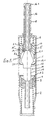
- the thread brake shown in Figure 1 contains an essentially cylindrical Brake housing 1, in the lower area of which a compression spring 2 against one Ring shoulder 1.2 pressed, piston-like designed brake ring carrier 3 housed is, which carries a first, lower brake ring 4.
- a cup-like support body 5 loaded by a compression spring 6 stored, which led out at the bottom of the brake housing 1 at the top Guide tube 8 is attached.
- the cup-like support body 5 is over its outer circumference distributed with several support shoulders 5.1, 5.2, the support surfaces in axial distance from each other.
- a thread inlet tube 16 is passed, which with a attached to its upper end, outwardly projecting bead body 16.1 is supported on the upper end of the guide tube 8.
- the lower end of the thread inlet tube 16 carries a second brake ring carrier 15, in which a second upper Brake ring 14 is inserted.
- the brake ring carrier 15 is in the cylinder chamber 5.3 of the cup-like support body 5 axially displaceably and is opposed by one supported the bottom of the cylinder chamber 5.3 compression spring 17.
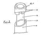
- the upper edge of the guide tube 8 is through an inclined surface formed, on which a nose-shaped projection 23 is formed.
- the bottom of the outwardly projecting bead 16.1 of the thread inlet tube 16 is corresponding to the the inclined surface forming the upper edge of the guide tube 8 is chamfered and over distributed around its circumference with a plurality of axially directed cutouts 22, whose bottoms each have different distances from the upper edge of the thread inlet pipe Have 16.
- the nose 23 By pulling up and turning the thread inlet tube 16, the nose 23 in snap a certain recess 22 and thus the height of the Change the brake ring carrier within the cup-like support body 5.
- a capsule-shaped brake cartridge 11 is supported between the brake rings 4 and 14, which are composed of two telescopic sleeve parts 12 and 13 is.
- the lower sleeve part 12 has essentially the shape of a cylinder sleeve with a lower spherical or dome-like end section.
- the second upper sleeve part 13 is also made of a cylindrical sleeve, which in its central portion a bulge 13.1 and a spherical or at its upper end has dome-like end section.
- This brake cartridge is a common construction element with an internal compression spring, against the force of which the two sleeve parts 12, 13 can be squeezed together.
- the braking force applied by the thread brake according to the invention can thus be in Depending on the spring force of the arranged inside the brake cartridge 11 Compression spring on the one hand and the respective positioning or height position of the two Brake rings 4, 14 can be set.
Landscapes
- Engineering & Computer Science (AREA)
- Mechanical Engineering (AREA)
- Textile Engineering (AREA)
- Spinning Or Twisting Of Yarns (AREA)
- Tension Adjustment In Filamentary Materials (AREA)
- Guides For Winding Or Rewinding, Or Guides For Filamentary Materials (AREA)
Description
Claims (7)
- Fadenbremse mit einem im wesentlichen rohförmigen Bremsengehäuse (1), in dem eine kapselförmige Bremspatrone (11) angeordnet ist, die erste und zweite teleskopartig gegen die Kraft einer Feder gegeneinander verschiebbare Hülsenteile (12, 13) aufweist, die im wesentlichen kugelige bzw. kalottenförmige, entgegengesetzt gerichtete Endabschnitte zur Bildung von Bremsflächen haben, die gegen im Bremsengehäuse starr und/oder in Achsrichtung verschiebbar angeordnete Bremsringe (4, 14) anliegen, deren Abstand voneinander veränderbar ist daß in das Bremsengehäuse (1) koaxial ein Führungsrohr (8) mündet, das einen in unterschiedlichen Höhenstellungen in dem Bremsengehäuse (1) arretierbaren, federbelasteten Stützkörper (5) trägt, dadurch gekennzeichnet daß innerhalb dieses Führungsrohres (8) ein in mindestens zwei Positionen gegenüber diesem Führungsrohr positionierbares Fadeneinlaufrohr (16) verläuft, dessen inneres Ende den Bremsring (14) trägt, der federbelastet an dem Stützkörper (5) abgestützt ist.
- Fadenbremse nach Anspruch 1, dadurch gekennzeichnet, daß der obere Rand des Führungsrohrs (8) durch eine Schrägfläche gebildet ist, an die ein nasenförmiger Vorsprung (23) angeformt ist, und daß das Fadeneinlaufrohr (16) zwecks Abstützung auf dem Führungsrohr (8) ein nach außen vorspringenden Wulst (16.1) aufweist, dessen unterer Rand entsprechend der den oberen Rand des Führungsrohres (8) bildenden Schrägfläche abgeschrägt und über seinen Umfang verteilt mit mehreren axial gerichteten Aussparungen (22) versehen ist, deren Böden jeweils unterschiedliche Abstände zum oberen Rand des Fadeneinlaufrohrs (16) haben.
- Fadenbremse nach Anspruch 1, dadurch gekennzeichnet, daß der Stützkörper (5) über seinen Umfang verteilt mehrere in axialem Abstand voneinander liegende Stützschultern (5.1, 5.2) hat, von denen jeweils einer gegen einen an der Innenwand des Bremsengehäuses befindlichen, radial gerichteten Vorsprung (1.1) zur Anlage bringbar ist.
- Fadenbremse nach Anspruch 1, dadurch gekennzeichnet, daß der Stützkörper (5) napfartig ausgebildet ist und eine Zylinderkammer (5.3) aufweist, innerhalb der der Bremsring (14) federbelastet abgestützt ist.
- Fadenbremse nach einem der Ansprüche 1 bis 4 , dadurch gekennzeichnet, daß der zweite Bremsring (4) in einem Bremsringträger (3) gelagert ist, der kolbenartig im Bremsengehäuse (1) geführt und gegen die Kraft einer Rückstellfeder (2) zur Freigabe der Bremspatrone von dieser wegbewegbar ist, und daß an der Innenwand des Bremsengehäuses (1) radial nach innen vorspringende Stützglieder (20) zur Abstützung der Bremspatrone (11) im Bereich einer Ausbauchung (13.1) der Bremspatrone vorgesehen sind.
- Spindel, insbesondere Doppeldraht-Zwimspindel, die mit einer Fadenbremse gemäß einem der Ansprüche 1 - 5 ausgerüstet ist.
- Doppeldraht-Zwirnmaschine, die mit Fadenbremse gemäß einem der Ansprüche 1 - 5 ausgerüstet ist.
Applications Claiming Priority (2)
| Application Number | Priority Date | Filing Date | Title |
|---|---|---|---|
| DE10032141A DE10032141A1 (de) | 2000-07-01 | 2000-07-01 | Fadenbremse und mit einer solchen Fadenbremse ausgerüstete Spindeln, Doppeldraht-Zwirnspindeln und Doppeldraht-Zwirnmaschinen |
| DE10032141 | 2000-07-01 |
Publications (2)
| Publication Number | Publication Date |
|---|---|
| EP1167592A1 EP1167592A1 (de) | 2002-01-02 |
| EP1167592B1 true EP1167592B1 (de) | 2003-12-10 |
Family
ID=7647514
Family Applications (1)
| Application Number | Title | Priority Date | Filing Date |
|---|---|---|---|
| EP01115417A Expired - Lifetime EP1167592B1 (de) | 2000-07-01 | 2001-06-27 | Fadenbremse und mit einer solchen Fadenbremse ausgerüstete Spindeln, Doppeldraht-Zwirnspindeln und Doppeldraht-Zwirnmaschinen |
Country Status (7)
| Country | Link |
|---|---|
| US (1) | US6401443B2 (de) |
| EP (1) | EP1167592B1 (de) |
| JP (1) | JP2002068596A (de) |
| CN (1) | CN1144902C (de) |
| CZ (1) | CZ301023B6 (de) |
| DE (2) | DE10032141A1 (de) |
| TR (1) | TR200400026T4 (de) |
Families Citing this family (6)
| Publication number | Priority date | Publication date | Assignee | Title |
|---|---|---|---|---|
| JP2008247560A (ja) * | 2007-03-30 | 2008-10-16 | Murata Mach Ltd | 張力付与装置 |
| DE102009058979A1 (de) * | 2009-12-18 | 2011-06-22 | Oerlikon Textile GmbH & Co. KG, 42897 | Fadenbremse für eine Doppeldrahtzwirnspindel |
| CN103541075A (zh) * | 2013-09-26 | 2014-01-29 | 吴江伊莱纺织科技有限公司 | 一种可精确调节的纱线张力器 |
| US20160334383A1 (en) * | 2013-12-20 | 2016-11-17 | Uster Technologies, Ag | Balling and Weighing Yarn |
| DE102015014299A1 (de) * | 2015-11-06 | 2017-05-11 | Saurer Germany Gmbh & Co. Kg | Außenfadenbremse, Kordier- oder Kabliermaschine mit einer Außenfadenbremse und Verfahren zum Betreiben einer solchen Kordier- oder Kabliermaschine |
| CN106367856B (zh) * | 2016-11-17 | 2019-01-22 | 安徽日发纺织机械有限公司 | 一种大卷装气动穿纱倍捻锭子 |
Family Cites Families (11)
| Publication number | Priority date | Publication date | Assignee | Title |
|---|---|---|---|---|
| FR1497288A (fr) * | 1965-10-25 | 1967-10-06 | Palitex Project Co Gmbh | Frein de fil, en particulier pour broches de retordage à double torsion |
| ES440037A1 (es) * | 1974-12-30 | 1977-02-16 | Palitex Project Co Gmbh | Perfeccionamientos relativos a husos de doble torsion con undispositivo de enhebrado accionado por aire a presion. |
| DE2830265C2 (de) * | 1978-07-10 | 1983-01-13 | Palitex Project-Company Gmbh, 4150 Krefeld | Doppeldraht-Zwirnspindel |
| DE2914656C2 (de) * | 1979-04-11 | 1982-04-22 | Palitex Project-Company Gmbh, 4150 Krefeld | Fadenbremse insbesondere für Doppeldraht-Zwirnspindeln |
| DE3000443A1 (de) * | 1980-01-08 | 1981-07-09 | Saurer-Allma Gmbh, 8960 Kempten | Einstellbare federbelastete fadenbremse fuer doppeldrahtzwirnspindeln |
| FR2493353A1 (fr) * | 1980-11-03 | 1982-05-07 | Verdol Sa | Dispositif d'enfilage pneumatique d'un fil dans une broche a double torsion |
| DE3104748C2 (de) * | 1981-02-11 | 1984-11-08 | Palitex Project-Company Gmbh, 4150 Krefeld | Pneumatisch durchfädelbare Fadenbremse, insbesondere für eine Doppeldraht-Zwirnspindel |
| DE3134763C2 (de) * | 1981-09-02 | 1983-12-01 | Palitex Project-Company Gmbh, 4150 Krefeld | Fadenbremse für eine Doppeldrahtzwirnspindel |
| DE4103286C2 (de) * | 1991-02-04 | 1993-10-28 | Palitex Project Co Gmbh | Doppeldraht-Zwirnspindel |
| EP0620301B1 (de) | 1993-04-13 | 1997-06-18 | Palitex Project-Company GmbH | Einrichtung zum Einstellen von Kapselfadenbremsen an Zwirnmaschinen, insbesondere Doppeldraht-Zwirnmaschinen |
| DE4343458C2 (de) * | 1993-12-20 | 1996-09-05 | Palitex Project Co Gmbh | Fadenbremse, insbesondere für Doppeldraht-Zwirnspindeln |
-
2000
- 2000-07-01 DE DE10032141A patent/DE10032141A1/de not_active Withdrawn
-
2001
- 2001-06-27 TR TR2004/00026T patent/TR200400026T4/xx unknown
- 2001-06-27 CZ CZ20012393A patent/CZ301023B6/cs not_active IP Right Cessation
- 2001-06-27 DE DE50101113T patent/DE50101113D1/de not_active Expired - Fee Related
- 2001-06-27 EP EP01115417A patent/EP1167592B1/de not_active Expired - Lifetime
- 2001-06-29 US US09/895,282 patent/US6401443B2/en not_active Expired - Fee Related
- 2001-06-30 CN CNB01125467XA patent/CN1144902C/zh not_active Expired - Fee Related
- 2001-07-02 JP JP2001201272A patent/JP2002068596A/ja active Pending
Also Published As
| Publication number | Publication date |
|---|---|
| CZ20012393A3 (cs) | 2002-02-13 |
| TR200400026T4 (tr) | 2004-02-23 |
| US6401443B2 (en) | 2002-06-11 |
| DE50101113D1 (de) | 2004-01-22 |
| CZ301023B6 (cs) | 2009-10-14 |
| CN1144902C (zh) | 2004-04-07 |
| EP1167592A1 (de) | 2002-01-02 |
| CN1333392A (zh) | 2002-01-30 |
| HK1043815A1 (en) | 2002-09-27 |
| JP2002068596A (ja) | 2002-03-08 |
| DE10032141A1 (de) | 2002-01-17 |
| US20020002814A1 (en) | 2002-01-10 |
Similar Documents
| Publication | Publication Date | Title |
|---|---|---|
| EP1167593A1 (de) | Fadenbremse und mit einer solchen Fadenbremse ausgerüstete Spindeln, Doppeldraht-Zwirnspindeln und Doppeldraht-Zwirnmaschinen | |
| EP0712802B1 (de) | Spulen-Adapter | |
| CH643211A5 (de) | Fadenbremse und mit einer derartigen fadenbremse ausgeruestete doppeldraht-zwirnspindel. | |
| DE3104748C2 (de) | Pneumatisch durchfädelbare Fadenbremse, insbesondere für eine Doppeldraht-Zwirnspindel | |
| EP0534183B1 (de) | Caddy für den voneinander unabhängigen Einzeltransport von Kopsen und Kopshülsen in einem Transportsystem einer Textilmaschine | |
| EP1167592A1 (de) | Fadenbremse und mit einer solchen Fadenbremse ausgerüstete Spindeln, Doppeldraht-Zwirnspindeln und Doppeldraht-Zwirnmaschinen | |
| DE4103286C2 (de) | Doppeldraht-Zwirnspindel | |
| DE1435238B2 (de) | Umspinnmaschine mit Spulentragern | |
| EP3215659B1 (de) | Doffergreifer mit zweigeteiltem gehäuse | |
| EP0665386B1 (de) | Scheibenbremse | |
| DE4343458C2 (de) | Fadenbremse, insbesondere für Doppeldraht-Zwirnspindeln | |
| DE4300389C2 (de) | Spulvorrichtung | |
| DE3243157A1 (de) | Fadenbremse mit zugeordneter druckluftbetaetigter einfaedelvorrichtung, insbesondere fuer doppeldraht-zwirnspindeln | |
| DE2828533C3 (de) | Bremspatrone für den axialen Einsatz in ein Fadenbremsengehäuse einer Zwirnspindel | |
| DE3015182C2 (de) | Fadenbremse | |
| DE2906811C2 (de) | Fadenbremse, insbesondere für Doppeldrahtzwirnspindeln | |
| DE2309578C3 (de) | Einstellbare federbelastete Fadenbremse, für Doppeldrahtzwirnspindeln | |
| DE1510833C (de) | Fadenbremse für Spinn- oder Zwirnmaschinen insbesondere Doppeldrahtzwirnmaschinen | |
| DE7409733U (de) | Halte- und Zentriervorrichtung für Spulen von Textilmaschinen | |
| DE19653359A1 (de) | Auflösewalze für eine Offenend-Spinnvorrichtung | |
| EP0772750A1 (de) | Radbremszylinder für trommelbremsen sowie trommelbremse mit radbremszylinder | |
| DE29513682U1 (de) | Vorrichtung zur Entnahme einer Bremspatrone aus einer Fadenbremse, insbesondere für eine Doppeldraht-Zwirnspindel | |
| DE1932941B2 (de) | Lieferspulenträger in Doppeldrahtzwirnspindeln für die Aufnahme von zwei axial übereinander angeordneten Lieferspulen | |
| DE2920970C2 (de) | Synchroneinrichtung | |
| DE2309578A1 (de) | Einstellbare federbelastete fadenbremse, insbesondere fuer doppeldrahtzwirnspindeln |
Legal Events
| Date | Code | Title | Description |
|---|---|---|---|
| PUAI | Public reference made under article 153(3) epc to a published international application that has entered the european phase |
Free format text: ORIGINAL CODE: 0009012 |
|
| AK | Designated contracting states |
Kind code of ref document: A1 Designated state(s): AT BE CH CY DE DK ES FI FR GB GR IE IT LI LU MC NL PT SE TR Kind code of ref document: A1 Designated state(s): CH DE FR GB IT LI TR |
|
| AX | Request for extension of the european patent |
Free format text: AL;LT;LV;MK;RO;SI |
|
| 17P | Request for examination filed |
Effective date: 20020625 |
|
| AKX | Designation fees paid |
Free format text: CH DE FR GB IT LI TR |
|
| GRAH | Despatch of communication of intention to grant a patent |
Free format text: ORIGINAL CODE: EPIDOS IGRA |
|
| GRAS | Grant fee paid |
Free format text: ORIGINAL CODE: EPIDOSNIGR3 |
|
| GRAA | (expected) grant |
Free format text: ORIGINAL CODE: 0009210 |
|
| AK | Designated contracting states |
Kind code of ref document: B1 Designated state(s): CH DE FR GB IT LI TR |
|
| REG | Reference to a national code |
Ref country code: GB Ref legal event code: FG4D Free format text: NOT ENGLISH |
|
| REG | Reference to a national code |
Ref country code: CH Ref legal event code: EP |
|
| REG | Reference to a national code |
Ref country code: IE Ref legal event code: FG4D Free format text: GERMAN |
|
| REF | Corresponds to: |
Ref document number: 50101113 Country of ref document: DE Date of ref document: 20040122 Kind code of ref document: P |
|
| REG | Reference to a national code |
Ref country code: CH Ref legal event code: PFA Owner name: VOLKMANN ZWEIGNIEDERLASSUNG DER SAURER GMBH & CO. Free format text: VOLKMANN GMBH#WEESERWEG 60#47804 KREFELD (DE) -TRANSFER TO- VOLKMANN ZWEIGNIEDERLASSUNG DER SAURER GMBH & CO. KG#WEESERWEG 60#47804 KREFELD (DE) Ref country code: CH Ref legal event code: NV Representative=s name: A. BRAUN, BRAUN, HERITIER, ESCHMANN AG PATENTANWAE |
|
| GBT | Gb: translation of ep patent filed (gb section 77(6)(a)/1977) |
Effective date: 20040315 |
|
| PGFP | Annual fee paid to national office [announced via postgrant information from national office to epo] |
Ref country code: TR Payment date: 20040628 Year of fee payment: 4 |
|
| REG | Reference to a national code |
Ref country code: IE Ref legal event code: FD4D |
|
| REG | Reference to a national code |
Ref country code: FR Ref legal event code: CD |
|
| ET | Fr: translation filed | ||
| PLBE | No opposition filed within time limit |
Free format text: ORIGINAL CODE: 0009261 |
|
| STAA | Information on the status of an ep patent application or granted ep patent |
Free format text: STATUS: NO OPPOSITION FILED WITHIN TIME LIMIT |
|
| 26N | No opposition filed |
Effective date: 20040913 |
|
| PGFP | Annual fee paid to national office [announced via postgrant information from national office to epo] |
Ref country code: GB Payment date: 20050527 Year of fee payment: 5 |
|
| PGFP | Annual fee paid to national office [announced via postgrant information from national office to epo] |
Ref country code: FR Payment date: 20050616 Year of fee payment: 5 |
|
| PGFP | Annual fee paid to national office [announced via postgrant information from national office to epo] |
Ref country code: CH Payment date: 20050622 Year of fee payment: 5 |
|
| PGFP | Annual fee paid to national office [announced via postgrant information from national office to epo] |
Ref country code: DE Payment date: 20050629 Year of fee payment: 5 |
|
| PG25 | Lapsed in a contracting state [announced via postgrant information from national office to epo] |
Ref country code: GB Free format text: LAPSE BECAUSE OF NON-PAYMENT OF DUE FEES Effective date: 20060627 |
|
| PG25 | Lapsed in a contracting state [announced via postgrant information from national office to epo] |
Ref country code: LI Free format text: LAPSE BECAUSE OF NON-PAYMENT OF DUE FEES Effective date: 20060630 Ref country code: CH Free format text: LAPSE BECAUSE OF NON-PAYMENT OF DUE FEES Effective date: 20060630 |
|
| PGFP | Annual fee paid to national office [announced via postgrant information from national office to epo] |
Ref country code: IT Payment date: 20060630 Year of fee payment: 6 |
|
| PG25 | Lapsed in a contracting state [announced via postgrant information from national office to epo] |
Ref country code: DE Free format text: LAPSE BECAUSE OF NON-PAYMENT OF DUE FEES Effective date: 20070103 |
|
| REG | Reference to a national code |
Ref country code: CH Ref legal event code: PL |
|
| GBPC | Gb: european patent ceased through non-payment of renewal fee |
Effective date: 20060627 |
|
| REG | Reference to a national code |
Ref country code: FR Ref legal event code: ST Effective date: 20070228 |
|
| PG25 | Lapsed in a contracting state [announced via postgrant information from national office to epo] |
Ref country code: FR Free format text: LAPSE BECAUSE OF NON-PAYMENT OF DUE FEES Effective date: 20060630 |
|
| PG25 | Lapsed in a contracting state [announced via postgrant information from national office to epo] |
Ref country code: IT Free format text: LAPSE BECAUSE OF NON-PAYMENT OF DUE FEES Effective date: 20070627 Ref country code: TR Free format text: LAPSE BECAUSE OF FAILURE TO SUBMIT A TRANSLATION OF THE DESCRIPTION OR TO PAY THE FEE WITHIN THE PRESCRIBED TIME-LIMIT Effective date: 20031210 |