EP1167644A2 - Auflager und Verfahren zur Herstellung von Kanalleitungen, insbesondere von Abwasserkanalleitungen, unter Verwendung von Muffenrohren - Google Patents
Auflager und Verfahren zur Herstellung von Kanalleitungen, insbesondere von Abwasserkanalleitungen, unter Verwendung von Muffenrohren Download PDFInfo
- Publication number
- EP1167644A2 EP1167644A2 EP01113951A EP01113951A EP1167644A2 EP 1167644 A2 EP1167644 A2 EP 1167644A2 EP 01113951 A EP01113951 A EP 01113951A EP 01113951 A EP01113951 A EP 01113951A EP 1167644 A2 EP1167644 A2 EP 1167644A2
- Authority
- EP
- European Patent Office
- Prior art keywords
- support
- sleeve
- pipes
- section
- supports
- Prior art date
- Legal status (The legal status is an assumption and is not a legal conclusion. Google has not performed a legal analysis and makes no representation as to the accuracy of the status listed.)
- Granted
Links
- 238000004519 manufacturing process Methods 0.000 title claims abstract description 6
- 238000000034 method Methods 0.000 claims abstract description 10
- 239000007787 solid Substances 0.000 claims abstract 2
- 239000000463 material Substances 0.000 claims description 5
- 230000035515 penetration Effects 0.000 claims description 3
- 230000007704 transition Effects 0.000 claims description 3
- 239000006260 foam Substances 0.000 claims description 2
- 230000000630 rising effect Effects 0.000 claims 1
- 239000010865 sewage Substances 0.000 claims 1
- 229910052572 stoneware Inorganic materials 0.000 description 6
- 238000011065 in-situ storage Methods 0.000 description 5
- 238000010276 construction Methods 0.000 description 4
- 229910000831 Steel Inorganic materials 0.000 description 2
- 230000009977 dual effect Effects 0.000 description 2
- 239000008187 granular material Substances 0.000 description 2
- 238000009434 installation Methods 0.000 description 2
- 238000004064 recycling Methods 0.000 description 2
- 239000010959 steel Substances 0.000 description 2
- 239000004793 Polystyrene Substances 0.000 description 1
- 229920005830 Polyurethane Foam Polymers 0.000 description 1
- 238000005056 compaction Methods 0.000 description 1
- 230000006835 compression Effects 0.000 description 1
- 238000007906 compression Methods 0.000 description 1
- 238000007796 conventional method Methods 0.000 description 1
- IYGDRNNNWIKNHO-UHFFFAOYSA-N gag-28 Chemical compound O=C1NC(=O)C(C)=CN1C1OC(COP(O)(=S)OC2C(OC(C2)N2C(N=C(N)C=C2)=O)COP(O)(=S)OC2C(OC(C2)N2C(NC(=O)C(C)=C2)=O)COP(O)(=S)OC2C(OC(C2)N2C(NC(=O)C(C)=C2)=O)COP(O)(=S)OC2C(OC(C2)N2C(N=C(N)C=C2)=O)COP(O)(=S)OC2C(OC(C2)N2C(N=C(N)C=C2)=O)COP(O)(=S)OC2C(OC(C2)N2C(N=C(N)C=C2)=O)COP(O)(=S)OC2C(OC(C2)N2C(NC(=O)C(C)=C2)=O)COP(O)(=S)OC2C(OC(C2)N2C(N=C(N)C=C2)=O)COP(O)(=S)OC2C(OC(C2)N2C(NC(=O)C(C)=C2)=O)COP(O)(=S)OC2C(OC(C2)N2C(N=C(N)C=C2)=O)COP(O)(=S)OC2C(OC(C2)N2C(NC(=O)C(C)=C2)=O)COP(O)(=S)OC2C(OC(C2)N2C3=NC=NC(N)=C3N=C2)COP(O)(=S)OC2C(OC(C2)N2C(N=C(N)C=C2)=O)COP(O)(=S)OC2C(OC(C2)N2C(N=C(N)C=C2)=O)COP(O)(=S)OC2C(OC(C2)N2C(N=C(N)C=C2)=O)COP(O)(=S)OC2C(OC(C2)N2C3=NC=NC(N)=C3N=C2)COP(O)(=S)OC2C(OC(C2)N2C(N=C(N)C=C2)=O)COP(O)(=S)OC2C(OC(C2)N2C3=C(C(NC(N)=N3)=O)N=C2)COP(O)(=S)OC2C(OC(C2)N2C(N=C(N)C=C2)=O)COP(O)(=S)OC2C(OC(C2)N2C(NC(=O)C(C)=C2)=O)COP(O)(=S)OC2C(OC(C2)N2C(N=C(N)C=C2)=O)COP(O)(=S)OC2C(OC(C2)N2C(NC(=O)C(C)=C2)=O)COP(O)(=S)OC2C(OC(C2)N2C(N=C(N)C=C2)=O)COP(S)(=O)OC2C(OC(C2)N2C3=C(C(NC(N)=N3)=O)N=C2)COP(O)(=S)OC2C(OC(C2)N2C(N=C(N)C=C2)=O)COP(O)(O)=S)C(OP(O)(=S)OCC2C(CC(O2)N2C3=NC=NC(N)=C3N=C2)O)C1 IYGDRNNNWIKNHO-UHFFFAOYSA-N 0.000 description 1
- 239000003292 glue Substances 0.000 description 1
- 239000012943 hotmelt Substances 0.000 description 1
- 239000000314 lubricant Substances 0.000 description 1
- 239000000155 melt Substances 0.000 description 1
- 239000004033 plastic Substances 0.000 description 1
- 229920003023 plastic Polymers 0.000 description 1
- 229920002223 polystyrene Polymers 0.000 description 1
- 239000004576 sand Substances 0.000 description 1
- 238000007711 solidification Methods 0.000 description 1
- 230000008023 solidification Effects 0.000 description 1
- 238000003860 storage Methods 0.000 description 1
Images




Classifications
-
- E—FIXED CONSTRUCTIONS
- E03—WATER SUPPLY; SEWERAGE
- E03F—SEWERS; CESSPOOLS
- E03F3/00—Sewer pipe-line systems
- E03F3/06—Methods of, or installations for, laying sewer pipes
-
- F—MECHANICAL ENGINEERING; LIGHTING; HEATING; WEAPONS; BLASTING
- F16—ENGINEERING ELEMENTS AND UNITS; GENERAL MEASURES FOR PRODUCING AND MAINTAINING EFFECTIVE FUNCTIONING OF MACHINES OR INSTALLATIONS; THERMAL INSULATION IN GENERAL
- F16L—PIPES; JOINTS OR FITTINGS FOR PIPES; SUPPORTS FOR PIPES, CABLES OR PROTECTIVE TUBING; MEANS FOR THERMAL INSULATION IN GENERAL
- F16L1/00—Laying or reclaiming pipes; Repairing or joining pipes on or under water
- F16L1/024—Laying or reclaiming pipes on land, e.g. above the ground
- F16L1/0243—Laying or reclaiming pipes on land, e.g. above the ground above ground
- F16L1/0246—Laying or reclaiming pipes on land, e.g. above the ground above ground at a certain height off the ground
-
- F—MECHANICAL ENGINEERING; LIGHTING; HEATING; WEAPONS; BLASTING
- F16—ENGINEERING ELEMENTS AND UNITS; GENERAL MEASURES FOR PRODUCING AND MAINTAINING EFFECTIVE FUNCTIONING OF MACHINES OR INSTALLATIONS; THERMAL INSULATION IN GENERAL
- F16L—PIPES; JOINTS OR FITTINGS FOR PIPES; SUPPORTS FOR PIPES, CABLES OR PROTECTIVE TUBING; MEANS FOR THERMAL INSULATION IN GENERAL
- F16L1/00—Laying or reclaiming pipes; Repairing or joining pipes on or under water
- F16L1/024—Laying or reclaiming pipes on land, e.g. above the ground
- F16L1/028—Laying or reclaiming pipes on land, e.g. above the ground in the ground
- F16L1/036—Laying or reclaiming pipes on land, e.g. above the ground in the ground the pipes being composed of sections of short length
-
- F—MECHANICAL ENGINEERING; LIGHTING; HEATING; WEAPONS; BLASTING
- F16—ENGINEERING ELEMENTS AND UNITS; GENERAL MEASURES FOR PRODUCING AND MAINTAINING EFFECTIVE FUNCTIONING OF MACHINES OR INSTALLATIONS; THERMAL INSULATION IN GENERAL
- F16L—PIPES; JOINTS OR FITTINGS FOR PIPES; SUPPORTS FOR PIPES, CABLES OR PROTECTIVE TUBING; MEANS FOR THERMAL INSULATION IN GENERAL
- F16L1/00—Laying or reclaiming pipes; Repairing or joining pipes on or under water
- F16L1/024—Laying or reclaiming pipes on land, e.g. above the ground
- F16L1/06—Accessories therefor, e.g. anchors
- F16L1/10—Accessories therefor, e.g. anchors for aligning
-
- F—MECHANICAL ENGINEERING; LIGHTING; HEATING; WEAPONS; BLASTING
- F16—ENGINEERING ELEMENTS AND UNITS; GENERAL MEASURES FOR PRODUCING AND MAINTAINING EFFECTIVE FUNCTIONING OF MACHINES OR INSTALLATIONS; THERMAL INSULATION IN GENERAL
- F16L—PIPES; JOINTS OR FITTINGS FOR PIPES; SUPPORTS FOR PIPES, CABLES OR PROTECTIVE TUBING; MEANS FOR THERMAL INSULATION IN GENERAL
- F16L3/00—Supports for pipes, cables or protective tubing, e.g. hangers, holders, clamps, cleats, clips, brackets
Definitions
- the invention relates to a support and a method according to the preambles of Claims 1 and 16, respectively.
- Socket pipes and in particular pipes made of stoneware with nominal widths from 100 to 1 400 mm usually have a circular, hollow cylindrical tubular shaft on the a sleeve protruding radially above it is formed on one end.
- the laying of such Socket pipes in a gravel / grit bedding according to DIN EN 1610 are mainly used in that it is attached to a belt or other support element that is wrapped around it hanging in a prepared trench with a crane, excavator or the like and then pulled into the sleeve of a previously installed pipe with the belt.
- the lower bedding layer previously placed and compacted in the trench before draining the pipes with a backhoe or the like in preselected Intervals of z. B. removed one meter each. This will keep it in use of socket pipes with a length of z. B. two meters only two supports each in the form of humps, each 0.50 m long.
- stoneware socket pipes can also be used after today reconditioned DIN 4033 can be laid in in-situ concrete, whereby this procedure also applies to The existence of a subsoil that is not sufficiently stable for gravel / grit bedding can be applied.
- the laying of socket pipes in in-situ concrete is controversial because of the in-situ concrete the mobility of the socket connections and a subsequent changes to the sewer line (e.g. installation of a branch) are impeded.
- a subsequent removal of concrete with a demolition hammer or the like can also the slightest carelessness lead to pipe damage and thereby the planned route of the Increase pipe replacement.
- the pipe laying is in-situ concrete significantly more expensive than laying in a gravel / grit bed.
- the supports On their The tops are the supports with a cylindrical concave extending over the entire length, the tubular shaft contact surface adapted to the shape of the tubular shaft ensures that the tubular shaft coming to rest on it lies evenly everywhere and laborious work to tamp the installed pipes and to compress them of the stuffed material can be omitted.
- the invention is therefore based on the technical problem, the support of the beginning designated genus so that it is particularly in the special needs takes into account the laying of socket pipes and especially stoneware pipes and enables simple, height and flush installation. Moreover the method of the type described at the beginning is intended for the supports designed in this way be adjusted.
- support 1 and 1a consist of massive, for. B. Prefabricated building parts made of concrete.
- the supports 1, 1a are particularly advantageous however made of recycled material, such as. B. in the dual system by Recycling the contents of the "yellow sacks" as granules. These granules can be used Increasing the final stiffness additionally supplemented with suitable plastics and as hot melt are poured into an appropriate mold, from which the finished support 1, 1a after the solidification of the melt is removed.
- the support 1, 1a then has a sufficient load-bearing capacity to unevenness in a schematically indicated in Fig. 2 Trench sole 2 on which it is laid to compensate.
- a A large number of supports 1, 1a in a manner known per se (DE 40 23 695 C2) one after the other laid along the trench bottom 2, thereby one for laying sleeve pipes 3, 3a (Fig. 2 to 4) to create suitable device.
- Each sleeve pipe 3, 3a a tubular shaft 4, 4a and at one end a radially projecting outward Sleeve 5, 5a.
- the pipes 3, 3a are laid, for. B.
- the supports 1 and 1a are just like the tubes 3, 3a preferably identical to each other, so that mainly only that Support 1 and the tube 3 are described in more detail. With the socket pipes 3, 3a can it is in particular stoneware pipes.
- the support has a preferably continuously flat surface as a standing surface serving underside 6 and two side surfaces 7, which are useful from the Bottom 6 obliquely upwards and outwards to the respective upper end of the Increase support 1.
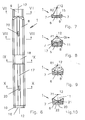
- the support 1 contains three sections arranged one behind the other in the longitudinal direction (FIGS. 5 and 6), namely a middle section 8, a first end section 9 and a second end section 10, which have the bottom side 6 and the side surfaces 7 in common.
- the middle section 8 has a cylindrical-concave upper side 11 (FIG. 8) which forms a bearing surface for the tubular shaft 4 (or 4a) of the socket pipe 3, 3a and a radius R 1 which is adapted to the outer radius of the tubular shaft 4 or corresponds to this having.
- the radius R 1 is based on an imaginary longitudinal axis 12 (FIGS. 7 to 10) which coincides with a longitudinal axis 14 of the tubular shaft (FIGS. 1, 3 and 4) when the tube 3 is properly placed on the support 1 or its upper side 11 is stored, and is therefore referred to below as "system axis 12".
- the upper side 15 (or 15a) thereby forms a sleeve bearing surface (FIGS.
- the radius R 2 can preferably be selected so that it is a preselected dimension larger than the outer socket radius of the pipe 3 to be installed, in order to compensate for dimensional tolerances from the pipe shank diameter and to avoid that the pipe 3 is supported only with the socket 5 is.
- the end section 10 provided at the opposite end in the longitudinal direction of the support 1 is designed as a height control section.
- it preferably has a cylindrical-concave surface 16, which forms a height control surface and - starting from the system axis 12 - has the same radius R 2 as the top 15 and is therefore arranged at the same height level as the top 6 ,
- a step is formed between the top sides 11 on the one hand and the top sides 15 and 16 on the other hand, which corresponds approximately to the height of the part of the sleeve 5 projecting over the outer circumference of the tubular shaft 4. Therefore, when laying a support 1, it is possible in a simple manner to arrange it in a height and alignment manner by placing its height control surface (e.g.
- the length of the entire support 1, 1a preferably corresponds essentially to the length of the associated socket pipe 3, 3a minus a socket penetration depth a (FIG. 2), which corresponds to the length of the pipe shaft section which, when the pipes 3, 3a are drawn into the sleeves 5, 5a comes to lie in these.
- the length of the supports 1, 1a can be smaller than the pipe length by an additional small safety distance t (FIG. 4) in order to be able to compensate for any length tolerances of the supports 1, 1a in the joint area.
- the lengths of the individual sections 8, 9 and 10 of the support 1 are different. As particularly shown in FIGS. 2 to 4, the length of the end section 9 is preferred about twice the length of the sleeve measured in the direction of the system axis 12 5, 5a and, if necessary, a working space greater than this measure. As a result, it is easily possible to always hold the pipes 3, 3a on the supports 1, 1a deposit that the sleeves 5, 5a on the associated tops 15, 15a of the End sections 9 come to rest and that forward, d. H. to the subsequently relocated Support 1 out, a certain excess remains, which allows the tops 16, 16a of the altitude control sections z. B. with a laser measuring device exactly on the Align tops 15, 15a.
- the top side 11 is preferably provided with a radius R 4 in the lowermost part, ie the bottom region of the tubular shaft support surface, with a continuous recess 17 in the longitudinal direction intended to improve the tubular shaft bearing. Without this recess 17, the tubular shaft 4, 4a could rest on the upper side 11 due to diameter tolerances with line contact.
- the width of the top 11 or the tubular shaft support surface can be determined, for example, by an angle ⁇ of 30 ° to 180 ° (FIG. 8). It is expediently determined as a function of the outer diameter of the tubular shaft 4, 4a and the predetermined tube load in the installed state. Values of 75 ° ⁇ ⁇ 120 120 ° have proven to be particularly advantageous, with values of ⁇ ⁇ 90 ° currently being considered the best.
- the central section 8 is preferably in a central region with a belt recess extending transversely to the system axis 12 18 provided (Fig. 5, 6, 9, 9a).
- This expediently has a cylindrical-concave surface with a radius R 3 starting from the system axis 12, which is at least so much larger than the radius R 1 that a belt which is used to lower and / or distort the pipe 3, 3a partially surrounds it can also be pulled away from the tubular shaft 4, 4a after it has been placed on the top 11.
- the length of the belt recess 18 parallel to the system axis 12 is preferably dimensioned so large that the belt can also be used to pull the tubular shaft 4,4a into the sleeve 5, 5a of the previously laid pipe 3, 3a, without reaching the end faces to initiate the recess 18.
- the length of the belt recess 18 z. B. 25 cm and the difference between the radii R 1 and R 3 z. B. 4 cm, the lateral transitions from the radius R 3 to the radius R 1 can be performed vertically or at 45 ° or another angle.
- the support according to the invention is preferably with at least one for Insert a support element 19 (Fig. 14, 15) provided certain recess 20.
- FIGS. 5, 6) are two such cutouts 20 in the middle section 8 available.
- the cutouts 20 on the one hand by a border to the top 11 of the central section 8, parallel to the System axis 12 extending longitudinal slot 21, on the other hand through from below this adjacent cylindrical cavity 22 is formed, the axis of which is perpendicular to System axis 12 stands.
- the Recesses 20, of course, in whole or in part in the end sections 9, 10 of the support 1 be formed.
- the support element 19 is preferably made of steel and has one according to FIGS. 14 and 15 Eyelet 24 and a round steel 25 or the like connected to it, on its free
- the end of a gag 28 extending transversely to this is fixed, the length of which is somewhat is smaller than the length of the longitudinal slots 21.
- the support element 19 with the toggle 26 can be inserted through the longitudinal slot 21 into the cavity 22, then in this rotated by approximately 90 ° and then inserted into the groove 23 by pulling on the eyelet 24.
- With a hanger, which is attached to the excavator bucket or the like, can now the support element 19 is gripped at its eyelet 24 and raised for transporting the support 1 be, the gag 26 remains securely engaged in the grooves 23.
- the top 11 of the support 1, which is designed as a tubular shaft support surface, can at least partially provided with a pad or with a foam (e.g. PU foam) are treated in order to protect the tubular shaft 4, 4a and / or to compensate for unevenness in the area of the tubular shafts 4, 4a due to dimensional tolerances. It would also be possible for a compressible pad made of polystyrene or the like. to glue into the recess. Accordingly, the top 15 for the sleeve support be treated.
- a foam e.g. PU foam
- the pipes 3, 3a are transported with the excavator by means of a belt, not shown, drained into the trench and placed on the supports 1, 1a.
- the belt loop is placed in the belt recess 18.
- the sleeve-free ends of the tubular shafts 4, 4a are drawn into the sleeves 5, 5a preferably with the help of the belt. After establishing the desired depth of penetration a (Fig. 2) the belt loop is released and through the belt recess 18 pulled out.
- the filling of the pipe trench after laying the sewer line can occur be made in the usual way.
- the concave, provided with the recess 17 top 11 of the middle sections 8 of the Pad 1, 1a ensure that the tubes 3, 3a already when placed on the device aligned in the longitudinal direction and held in their vertical and lateral position and be centered. It is therefore not possible to move the pipes out of their target axis. It is also advantageous that a pipe laying can only be carried out in a simple manner Socket side of the pipes 3, 3a ago is possible. This allows the width of the trenches Pipes with diameters up to 600 mm according to DIN EN 1610 (table 1) to OD + Reduce 0.4 m.
- the invention is not restricted to the exemplary embodiment described, which is based on can be modified in many ways. This applies in particular to the described dimensions and designs of the various support parts.
- the supports can also be used to lay pipes other than stoneware pipes be used.
- the different tops or contact surfaces 11 or 15, 16 when using pipes, the other as a circular cylindrical outer jacket have, be provided with appropriately adapted shapes. It would be further possible, the tops 11 and 15, 16 before placing the tubes 3, 3a with a Brush lubricant so that the pipes 3, 3a when pulled into the sleeves 5, 5a stay largely tension-free.
- the altitude control section could also be different be designed as shown.
- the different characteristics also used in combinations other than those shown and described can be, e.g. B. with a mechanical laying of supports 1, 1a and tube 3, 3a.
Landscapes
- Engineering & Computer Science (AREA)
- General Engineering & Computer Science (AREA)
- Mechanical Engineering (AREA)
- Health & Medical Sciences (AREA)
- Life Sciences & Earth Sciences (AREA)
- Hydrology & Water Resources (AREA)
- Public Health (AREA)
- Water Supply & Treatment (AREA)
- Sewage (AREA)
- Supports For Pipes And Cables (AREA)
- Sink And Installation For Waste Water (AREA)
Abstract
Description
Claims (18)
- Auflager für ein Muffenrohr (3, 3a), das einen Rohrschaft (4, 4a) und an einem Ende davon eine Muffe (5, 5a) aufweist, zur Herstellung von Kanalleitungen, insbesondere Abwasserkanalleitungen, bestehend aus einem massiven Baufertigteil mit einer zylindrischkonkaven Oberseite (11), die eine Rohrschaft-Auflagefläche für das Muffenrohr (3, 3a) bildet und - ausgehend von einer Systemachse (12) - einen an den Außenradius des Rohrschafts (4, 4a) angepaßten Radius (R1) hat, dadurch gekennzeichnet, daß es einen mit der Rohrschaft-Auflagefläche versehenen Mittelabschnitt (8) und zwei in Längsrichtung an diesen anschließende Endabschnitte (9, 10) aufweist, wobei der eine Endabschnitt (9) ein Muffen-Auflageabschnitt ist, der eine zylindrisch-konkave Oberseite (15, 15a) besitzt, die eine Muffen-Auflagefläche für die Muffen (5, 5a) bildet und - ausgehend von der Systemachse (12) - einen an den Außenradius der Muffen (5, 5a) angepaßten Radius (R2) hat, während der andere Endabschnitt (10) als Höhenlage-Kontrollabschnitt ausgebildet ist.
- Auflager nach Anspruch 1, dadurch gekennzeichnet, daß der Höhenlage-Kontrollabschnitt eine zylindrisch-konkave Oberseite (16) aufweist, die einen Höhenlage-Kontrollfläche bildet und - ausgehend von der Systemachse (12) - einen an den Außenradius der Muffe (5, 5a) angepaßten Radius (R2) hat.
- Auflager nach Anspruch 1 oder 2, dadurch gekennzeichnet, daß es eine Länge besitzt, die im wesentlichen gleich der Länge des Muffenrohrs (3, 3a) abzüglich einer Muffeneindringtiefe (a) ist.
- Auflager nach einem der Ansprüche 1 bis 3, dadurch gekennzeichnet, daß der Muffen-Auflageabschnitt (9) durchgehend (R2) eine Länge besitzt, die etwa der doppelten Muffenlänge entspricht.
- Auflager nach einem der Ansprüche 1 bis 4, dadurch gekennzeichnet, daß der Höhenlage-Kontrollabschnitt (10) durchgehend (R2) eine kleinere Länge als der Muffen-Auflageabschnitt (9) aufweist.
- Auflager nach einem der Ansprüche 1 bis 5, dadurch gekennzeichnet, daß der Mittelabschnitt (8) in einem Sohlbereich seiner Oberseite (11) mit einer in Längsrichtung durchgehenden Vertiefung (17) mit einem Radius (R4) versehen ist.
- Auflager nach einem der Ansprüche 1 bis 6, dadurch gekennzeichnet, daß es mit einer Unterseite (6) und zwei von dieser schräg nach außen ansteigenden Seitenflächen (7) versehen ist.
- Auflager nach einem der Ansprüche 1 bis 7, dadurch gekennzeichnet, daß sich zumindest die Oberseite (11) des Mittelabschnitts (8) über einen Auflagewinkel (α) von 30° bis 180°, vorzugweise 75° bis 120° erstreckt.
- Auflager nach einem der Ansprüche 1 bis 8, dadurch gekennzeichnet, daß der Mittelabschnitt (8) in einem mittleren Bereich mit einer quer zur Systemachse (12) erstreckten Gurt-Ausnehmung (18) versehen ist.
- Auflager nach Anspruch 9, dadurch gekennzeichnet, daß die Gurt-Ausnehmung (18) eine zylindrisch-konkave Oberfläche hat.
- Auflager nach einem der Ansprüche 1 bis 10, dadurch gekennzeichnet, daß es mit wenigstens einer zum Einsetzen eines Tragelements (19) bestimmten Aussparung (20) versehen ist.
- Auflager nach Anspruch 11, dadurch gekennzeichnet, daß die Aussparung (20) einen an die Oberseite (11) des Mittelabschnitts (8) und/oder eines Endabschnitts (9, 10) grenzenden, parallel zur Systemachse (12) verlaufenden Längsschlitz (21) und einen an diesen von unten her angrenzenden, zylindrischen Hohlraum (22) mit einer quer zur Systemachse (12) verlaufenden Achse aufweist.
- Auflager nach Anspruch 12, dadurch gekennzeichnet, daß in einen Übergangsbereich zwischen dem Längsschlitz (21) und dem Hohlraum (22) eine quer zum Längsschlitz (21) verlaufende Nut (23) eingearbeitet ist.
- Auflager nach einem der Ansprüche 1 bis 13, dadurch gekennzeichnet, daß es aus Recycling-Material hergestellt ist.
- Auflager nach einem der Ansprüche 1 bis 14, dadurch gekennzeichnet, daß die Rohrschaft-Auflagefläche (11) und/oder die Muffen-Auflagefläche (15) zumindest teilweise mit einem Auflagepolster versehen oder mit einem Schaumstoff behandelt ist.
- Verfahren zur Herstellung einer Kanalleitung, insbesondere einer Abwasser-Kanalleitung, unter Anwendung von Auflagern (1, 1a) nach einem oder mehreren der Ansprüche 1 bis 15 und Muffenrohren (3, 3a), die Rohrschäfte (4, 4a) und an ihren einen Enden je eine Muffe (5, 5a) aufweisen, dadurch gekennzeichnet, daß eine Vielzahl der Auflager (1, 1a) so hintereinander angeordnet wird, daß jeweils ein Muffen-Auflageabschnitt (9) einem Höhenlage-Kontrollabschnitt (10) gegenübersteht, daß dabei die Höhenlage-Kontrollabschnitte (10) in ihrer Höhenlage auf die Muffen-Auflageabschnitte (9) ausgerichtet werden, daß die Muffenrohre (3, 3a) so auf den Auflagern (1, 1a) abgelegt werden, daß die Rohrschäfte (4, 4a) auf den Rohrschaft-Auflageflächen (11, 11a) und die Muffen (5, 5a) auf den Muffen-Auflageflächen (15, 15a) zu liegen kommen, und daß die Muffenrohre (3, 3a) dann zur Herstellung von Muffenverbindungen auf den Auflagern (1, 1a) verzogen werden.
- Verfahren nach Anspruch 16, dadurch gekennzeichnet, daß das Verziehen der Muffenrohre (3, 3a) mit Hilfe eines diese umschlingenden Gurts erfolgt und der Gurt beim Ablegen der Muffenrohre (3, 3a) auf den Auflagern (1, 1a) in die betreffende Gurt-Ausnehmung (18) eingelegt wird.
- Verfahren nach Anspruch 16 oder 17, dadurch gekennzeichnet, daß die Auflager (1, 1a) mit Hilfe von Knebel (26) aufweisenden Tragelementen (19) transportiert und abgelegt werden, indem die Knebel (26) durch die Längsschlitze (21) hindurch in die zylindrischen Hohlräume (22) eingeführt, dann in diesen gedreht und danach in die Nuten (23) eingelegt werden.
Applications Claiming Priority (2)
| Application Number | Priority Date | Filing Date | Title |
|---|---|---|---|
| DE20010650U | 2000-06-21 | ||
| DE20010650U DE20010650U1 (de) | 2000-06-21 | 2000-06-21 | Auflager zur Herstellung von Kanalleitungen, insbesondere Abwasserkanalleitungen, unter Verwendung von Muffenrohren |
Publications (3)
| Publication Number | Publication Date |
|---|---|
| EP1167644A2 true EP1167644A2 (de) | 2002-01-02 |
| EP1167644A3 EP1167644A3 (de) | 2003-02-05 |
| EP1167644B1 EP1167644B1 (de) | 2006-09-13 |
Family
ID=7942881
Family Applications (1)
| Application Number | Title | Priority Date | Filing Date |
|---|---|---|---|
| EP01113951A Expired - Lifetime EP1167644B1 (de) | 2000-06-21 | 2001-06-08 | Auflager und Verfahren zur Herstellung von Kanalleitungen, insbesondere von Abwasserkanalleitungen, unter Verwendung von Muffenrohren |
Country Status (6)
| Country | Link |
|---|---|
| EP (1) | EP1167644B1 (de) |
| AT (1) | ATE339558T1 (de) |
| CZ (1) | CZ20012302A3 (de) |
| DE (2) | DE20010650U1 (de) |
| PL (1) | PL348176A1 (de) |
| SK (1) | SK8942001A3 (de) |
Families Citing this family (3)
| Publication number | Priority date | Publication date | Assignee | Title |
|---|---|---|---|---|
| NL2015528B1 (nl) * | 2015-09-30 | 2017-04-20 | Gmb Civiel B V | Werkwijze voor het renoveren van een buis en een ondersteuningselement voor het renoveren van een buis. |
| CN111059353B (zh) * | 2019-12-30 | 2021-07-23 | 青岛华德仪表工程有限公司 | 一种给水管道的施工方法 |
| CN120799189B (zh) * | 2025-08-15 | 2025-12-23 | 湖南振辉管业有限公司 | 一种拖拉管材的防脱接口 |
Family Cites Families (5)
| Publication number | Priority date | Publication date | Assignee | Title |
|---|---|---|---|---|
| GB2099953B (en) * | 1981-06-02 | 1984-10-24 | Hepworth Plastics Ltd | Laying pipelines in trenches |
| DE9003966U1 (de) * | 1990-04-05 | 1990-06-13 | Giesler, Norbert, 3503 Lohfelden | Vorrichtung zum Verlegen eines Rohrs bei der Herstellung von aus Rohren zusammengesetzten Kanalleitungen, insbesondere Abwasserkanalleitungen |
| JP2561424B2 (ja) * | 1993-06-18 | 1996-12-11 | 株式会社シーエスエンジニアズ | 埋設パッド材及びそれを使用する管路の埋設工法 |
| JP4443671B2 (ja) * | 1998-07-03 | 2010-03-31 | 古河電気工業株式会社 | 管路用管台及びそれを用いた管路組立方法 |
| DE19849142A1 (de) * | 1998-10-24 | 2000-04-27 | Sander Karl Heinz Gmbh & Co Kg | Betonrohrleitungssystem |
-
2000
- 2000-06-21 DE DE20010650U patent/DE20010650U1/de not_active Expired - Lifetime
-
2001
- 2001-06-08 AT AT01113951T patent/ATE339558T1/de not_active IP Right Cessation
- 2001-06-08 EP EP01113951A patent/EP1167644B1/de not_active Expired - Lifetime
- 2001-06-08 DE DE50110985T patent/DE50110985D1/de not_active Expired - Fee Related
- 2001-06-20 PL PL01348176A patent/PL348176A1/xx unknown
- 2001-06-20 SK SK894-2001A patent/SK8942001A3/sk unknown
- 2001-06-21 CZ CZ20012302A patent/CZ20012302A3/cs unknown
Also Published As
| Publication number | Publication date |
|---|---|
| PL348176A1 (en) | 2002-01-02 |
| EP1167644A3 (de) | 2003-02-05 |
| CZ20012302A3 (cs) | 2002-02-13 |
| DE50110985D1 (de) | 2006-10-26 |
| SK8942001A3 (en) | 2002-01-07 |
| DE20010650U1 (de) | 2001-10-31 |
| ATE339558T1 (de) | 2006-10-15 |
| EP1167644B1 (de) | 2006-09-13 |
Similar Documents
| Publication | Publication Date | Title |
|---|---|---|
| AT512161B1 (de) | Rammspitze für einen im Wesentlichen rohrförmigen, insbesondere hohlzylindrischen, Rammpfahl | |
| EP2921599B1 (de) | Element zum aufbau eines kanals und verfahren zur verlegung von elementen | |
| EP2067590B1 (de) | Verfahren zur Herstellung von Verbundrohren | |
| DE4441719C1 (de) | Verfahren zum Auskleiden eines Schachtes, insbesondere eines Brunnenschachtes | |
| DE4005032A1 (de) | Vorrichtung und verfahren zum aufbringen einer kraft zwischen einer bodenplatte und einem gruendungselement | |
| EP1167644B1 (de) | Auflager und Verfahren zur Herstellung von Kanalleitungen, insbesondere von Abwasserkanalleitungen, unter Verwendung von Muffenrohren | |
| DE69514160T2 (de) | Verfahren zum Auskleiden von Tunneln | |
| DE202019100752U1 (de) | Verbauvorrichtung | |
| DE3601587C2 (de) | ||
| DE4319239C2 (de) | Verfahren und Vorrichtung zur Nachgründung tragender Bauwerkteile oder von Fundamentteilen | |
| CH498987A (de) | Schacht aus Fertigteilen | |
| DE4023695C2 (de) | Vorrichtung zum Verlegen von aus Rohren bestehenden Kanalleitungen, insbesondere Abwasserkanalleitungen | |
| DE4138781C2 (de) | Verfahren und Schlauchelement zum gleichmäßigen Absetzen einer Last auf einer Auflagerfläche | |
| CH713190A2 (de) | Vorrichtung und Verfahren zur Verbindung von zwei Bauteilen in einer bestimmten relativen Ausrichtung sowie damit erstelltes Betonbauwerk. | |
| AT396604B (de) | Verfahren und einrichtung zum herstellen eines stranges aus einzelelementen unter wasser | |
| DE10124069C1 (de) | Grabenverbau für Rohr- und Medienleitungen | |
| CH708408B1 (de) | Verfahren und Vorrichtung zum Bau eines Tunnels. | |
| DE19849142A1 (de) | Betonrohrleitungssystem | |
| DE10345124B4 (de) | Vorrichtung zur Auskleidung eines Kanals | |
| DE202025106849U1 (de) | Rigolenstein | |
| DE2531007B2 (de) | Verfahren und Vorrichtung zur Erstellung von Arbeitsschächten innerhalb im Schildvortrieb aufgefahrener Gräben | |
| EP0943857A2 (de) | Verfahren zum segmentweisen Lösen von im Boden verlegten gemufften Rohrleitungen und Vorrichtung zur Durchführung des Verfahrens | |
| DE102016004261A1 (de) | Bewehrungsvorrichtung ASTO vario 2016 Bewehrungsvorrichtung zum Erstellen einer lagerbestimmten Bewehrung eines Bauwerks | |
| DE29701152U1 (de) | Betonrohrteil, insbesondere in Form eines Tübbingteiles | |
| DE1708617C3 (de) | Schacht aus Fertigteilen |
Legal Events
| Date | Code | Title | Description |
|---|---|---|---|
| PUAI | Public reference made under article 153(3) epc to a published international application that has entered the european phase |
Free format text: ORIGINAL CODE: 0009012 |
|
| AK | Designated contracting states |
Kind code of ref document: A2 Designated state(s): AT BE CH CY DE DK ES FI FR GB GR IE IT LI LU MC NL PT SE TR |
|
| AX | Request for extension of the european patent |
Free format text: AL;LT;LV;MK;RO;SI |
|
| PUAL | Search report despatched |
Free format text: ORIGINAL CODE: 0009013 |
|
| AK | Designated contracting states |
Designated state(s): AT BE CH CY DE DK ES FI FR GB GR IE IT LI LU MC NL PT SE TR |
|
| AX | Request for extension of the european patent |
Extension state: AL LT LV MK RO SI |
|
| 17P | Request for examination filed |
Effective date: 20030805 |
|
| AKX | Designation fees paid |
Designated state(s): AT BE CH CY DE DK ES FI FR GB GR IE IT LI LU MC NL PT SE TR |
|
| 17Q | First examination report despatched |
Effective date: 20031208 |
|
| GRAP | Despatch of communication of intention to grant a patent |
Free format text: ORIGINAL CODE: EPIDOSNIGR1 |
|
| GRAS | Grant fee paid |
Free format text: ORIGINAL CODE: EPIDOSNIGR3 |
|
| GRAA | (expected) grant |
Free format text: ORIGINAL CODE: 0009210 |
|
| AK | Designated contracting states |
Kind code of ref document: B1 Designated state(s): AT BE CH CY DE DK ES FI FR GB GR IE IT LI LU MC NL PT SE TR |
|
| PG25 | Lapsed in a contracting state [announced via postgrant information from national office to epo] |
Ref country code: FI Free format text: LAPSE BECAUSE OF FAILURE TO SUBMIT A TRANSLATION OF THE DESCRIPTION OR TO PAY THE FEE WITHIN THE PRESCRIBED TIME-LIMIT Effective date: 20060913 Ref country code: IT Free format text: LAPSE BECAUSE OF FAILURE TO SUBMIT A TRANSLATION OF THE DESCRIPTION OR TO PAY THE FEE WITHIN THE PRESCRIBED TIME-LIMIT;WARNING: LAPSES OF ITALIAN PATENTS WITH EFFECTIVE DATE BEFORE 2007 MAY HAVE OCCURRED AT ANY TIME BEFORE 2007. THE CORRECT EFFECTIVE DATE MAY BE DIFFERENT FROM THE ONE RECORDED. Effective date: 20060913 Ref country code: NL Free format text: LAPSE BECAUSE OF FAILURE TO SUBMIT A TRANSLATION OF THE DESCRIPTION OR TO PAY THE FEE WITHIN THE PRESCRIBED TIME-LIMIT Effective date: 20060913 Ref country code: IE Free format text: LAPSE BECAUSE OF FAILURE TO SUBMIT A TRANSLATION OF THE DESCRIPTION OR TO PAY THE FEE WITHIN THE PRESCRIBED TIME-LIMIT Effective date: 20060913 Ref country code: GB Free format text: LAPSE BECAUSE OF FAILURE TO SUBMIT A TRANSLATION OF THE DESCRIPTION OR TO PAY THE FEE WITHIN THE PRESCRIBED TIME-LIMIT Effective date: 20060913 |
|
| REG | Reference to a national code |
Ref country code: GB Ref legal event code: FG4D Free format text: NOT ENGLISH |
|
| REG | Reference to a national code |
Ref country code: CH Ref legal event code: EP |
|
| REG | Reference to a national code |
Ref country code: IE Ref legal event code: FG4D Free format text: LANGUAGE OF EP DOCUMENT: GERMAN |
|
| REF | Corresponds to: |
Ref document number: 50110985 Country of ref document: DE Date of ref document: 20061026 Kind code of ref document: P |
|
| PG25 | Lapsed in a contracting state [announced via postgrant information from national office to epo] |
Ref country code: DK Free format text: LAPSE BECAUSE OF FAILURE TO SUBMIT A TRANSLATION OF THE DESCRIPTION OR TO PAY THE FEE WITHIN THE PRESCRIBED TIME-LIMIT Effective date: 20061213 Ref country code: SE Free format text: LAPSE BECAUSE OF FAILURE TO SUBMIT A TRANSLATION OF THE DESCRIPTION OR TO PAY THE FEE WITHIN THE PRESCRIBED TIME-LIMIT Effective date: 20061213 |
|
| PG25 | Lapsed in a contracting state [announced via postgrant information from national office to epo] |
Ref country code: ES Free format text: LAPSE BECAUSE OF FAILURE TO SUBMIT A TRANSLATION OF THE DESCRIPTION OR TO PAY THE FEE WITHIN THE PRESCRIBED TIME-LIMIT Effective date: 20061224 |
|
| NLV1 | Nl: lapsed or annulled due to failure to fulfill the requirements of art. 29p and 29m of the patents act | ||
| PG25 | Lapsed in a contracting state [announced via postgrant information from national office to epo] |
Ref country code: PT Free format text: LAPSE BECAUSE OF FAILURE TO SUBMIT A TRANSLATION OF THE DESCRIPTION OR TO PAY THE FEE WITHIN THE PRESCRIBED TIME-LIMIT Effective date: 20070302 |
|
| GBV | Gb: ep patent (uk) treated as always having been void in accordance with gb section 77(7)/1977 [no translation filed] |
Effective date: 20060913 |
|
| REG | Reference to a national code |
Ref country code: IE Ref legal event code: FD4D |
|
| EN | Fr: translation not filed | ||
| PLBE | No opposition filed within time limit |
Free format text: ORIGINAL CODE: 0009261 |
|
| STAA | Information on the status of an ep patent application or granted ep patent |
Free format text: STATUS: NO OPPOSITION FILED WITHIN TIME LIMIT |
|
| PGFP | Annual fee paid to national office [announced via postgrant information from national office to epo] |
Ref country code: DE Payment date: 20070816 Year of fee payment: 7 |
|
| 26N | No opposition filed |
Effective date: 20070614 |
|
| BERE | Be: lapsed |
Owner name: GIESLER, NORBERT Effective date: 20070630 |
|
| PG25 | Lapsed in a contracting state [announced via postgrant information from national office to epo] |
Ref country code: MC Free format text: LAPSE BECAUSE OF NON-PAYMENT OF DUE FEES Effective date: 20070630 |
|
| REG | Reference to a national code |
Ref country code: CH Ref legal event code: PL |
|
| PG25 | Lapsed in a contracting state [announced via postgrant information from national office to epo] |
Ref country code: BE Free format text: LAPSE BECAUSE OF NON-PAYMENT OF DUE FEES Effective date: 20070630 |
|
| PG25 | Lapsed in a contracting state [announced via postgrant information from national office to epo] |
Ref country code: LI Free format text: LAPSE BECAUSE OF NON-PAYMENT OF DUE FEES Effective date: 20070630 Ref country code: FR Free format text: LAPSE BECAUSE OF FAILURE TO SUBMIT A TRANSLATION OF THE DESCRIPTION OR TO PAY THE FEE WITHIN THE PRESCRIBED TIME-LIMIT Effective date: 20070518 Ref country code: GR Free format text: LAPSE BECAUSE OF FAILURE TO SUBMIT A TRANSLATION OF THE DESCRIPTION OR TO PAY THE FEE WITHIN THE PRESCRIBED TIME-LIMIT Effective date: 20061214 Ref country code: CH Free format text: LAPSE BECAUSE OF NON-PAYMENT OF DUE FEES Effective date: 20070630 |
|
| PG25 | Lapsed in a contracting state [announced via postgrant information from national office to epo] |
Ref country code: AT Free format text: LAPSE BECAUSE OF NON-PAYMENT OF DUE FEES Effective date: 20070608 |
|
| PG25 | Lapsed in a contracting state [announced via postgrant information from national office to epo] |
Ref country code: FR Free format text: LAPSE BECAUSE OF FAILURE TO SUBMIT A TRANSLATION OF THE DESCRIPTION OR TO PAY THE FEE WITHIN THE PRESCRIBED TIME-LIMIT Effective date: 20060913 |
|
| PG25 | Lapsed in a contracting state [announced via postgrant information from national office to epo] |
Ref country code: DE Free format text: LAPSE BECAUSE OF NON-PAYMENT OF DUE FEES Effective date: 20090101 |
|
| PG25 | Lapsed in a contracting state [announced via postgrant information from national office to epo] |
Ref country code: LU Free format text: LAPSE BECAUSE OF NON-PAYMENT OF DUE FEES Effective date: 20070608 Ref country code: CY Free format text: LAPSE BECAUSE OF FAILURE TO SUBMIT A TRANSLATION OF THE DESCRIPTION OR TO PAY THE FEE WITHIN THE PRESCRIBED TIME-LIMIT Effective date: 20060913 |
|
| PG25 | Lapsed in a contracting state [announced via postgrant information from national office to epo] |
Ref country code: TR Free format text: LAPSE BECAUSE OF FAILURE TO SUBMIT A TRANSLATION OF THE DESCRIPTION OR TO PAY THE FEE WITHIN THE PRESCRIBED TIME-LIMIT Effective date: 20060913 |