EP1167708B1 - Vorrichtung zur Nachbehandlung von Dieselabgasen - Google Patents
Vorrichtung zur Nachbehandlung von Dieselabgasen Download PDFInfo
- Publication number
- EP1167708B1 EP1167708B1 EP01115227A EP01115227A EP1167708B1 EP 1167708 B1 EP1167708 B1 EP 1167708B1 EP 01115227 A EP01115227 A EP 01115227A EP 01115227 A EP01115227 A EP 01115227A EP 1167708 B1 EP1167708 B1 EP 1167708B1
- Authority
- EP
- European Patent Office
- Prior art keywords
- filter
- heating element
- exhaust gas
- grooved depression
- soot
- Prior art date
- Legal status (The legal status is an assumption and is not a legal conclusion. Google has not performed a legal analysis and makes no representation as to the accuracy of the status listed.)
- Expired - Lifetime
Links
Images

Classifications
-
- F—MECHANICAL ENGINEERING; LIGHTING; HEATING; WEAPONS; BLASTING
- F01—MACHINES OR ENGINES IN GENERAL; ENGINE PLANTS IN GENERAL; STEAM ENGINES
- F01N—GAS-FLOW SILENCERS OR EXHAUST APPARATUS FOR MACHINES OR ENGINES IN GENERAL; GAS-FLOW SILENCERS OR EXHAUST APPARATUS FOR INTERNAL-COMBUSTION ENGINES
- F01N3/00—Exhaust or silencing apparatus having means for purifying, rendering innocuous, or otherwise treating exhaust
- F01N3/02—Exhaust or silencing apparatus having means for purifying, rendering innocuous, or otherwise treating exhaust for cooling, or for removing solid constituents of, exhaust
- F01N3/021—Exhaust or silencing apparatus having means for purifying, rendering innocuous, or otherwise treating exhaust for cooling, or for removing solid constituents of, exhaust by means of filters
- F01N3/023—Exhaust or silencing apparatus having means for purifying, rendering innocuous, or otherwise treating exhaust for cooling, or for removing solid constituents of, exhaust by means of filters using means for regenerating the filters, e.g. by burning trapped particles
- F01N3/027—Exhaust or silencing apparatus having means for purifying, rendering innocuous, or otherwise treating exhaust for cooling, or for removing solid constituents of, exhaust by means of filters using means for regenerating the filters, e.g. by burning trapped particles using electric or magnetic heating means
Definitions
- the present invention relates to a device for Aftertreatment of diesel exhaust gases according to the generic term of Claim 1.
- the particle filters are made of porous material, preferably made of ceramic. Taking exhaust back pressure into account, The ceramic has soot storage and filter action Honeycomb filter the most favorable behavior. Since the Flow resistance of the particle filter with increasing soot load increases, is a regular particle oxidation (Filter regeneration) necessary. If this is sufficient Residual oxygen content in the exhaust gas temperatures above 470 up to 600 ° C (soot ignition temperature) required.
- the exhaust gas temperature can be increased by secondary energy supply until the filter regeneration begins.
- the required power requirement is between 9 kW / dm 3 displacement (WR Wade including Diesel Particulate Trap Regeneration Techniques SAE 810 118) and 14 kW / dm 3 displacement (WR Wade including Thermal and Catalytic Regeneration of Diesel Particulate Traps SAE 830 083).
- Heating outputs above 1 kW are only included in vehicles Depicting burners. Burners need for a safe Operation of complex control and monitoring systems. Of the caused by a burner system with bypass control The additional fuel consumption is in the regeneration cycle V. D. Rao about 2%.
- US 4872889 discloses a device of the generic type Kind, with here heating wires across to the current entry side Surface of the filter body Grooves run and loop-shaped in the filter channels protrude.
- a cover plate covers the relevant end face of the filter body.
- EP 233860 A2 proposes the arrangement to act in a punctiform manner Cartridges in the filter body.
- the invention has for its object a device of the type specified at the outset, on the one hand with low electrical energy of the vehicle electrical system Motor vehicle manages and on the other hand a safe filter regeneration enabled even with a low soot load.
- a device for the aftertreatment of diesel exhaust gases with the characteristics of claim 1.
- the device for aftertreatment of diesel exhaust gases thus comprises a housing with an exhaust gas inlet and an exhaust gas outlet, a, preferably ceramic, Filter body and at least one exhaust gas inlet side heating element arranged on the filter body.
- the feature of the device according to the invention is that Embedding the at least one electrical heating element in at least one groove-like depression, the inflow side arranged in the filter body and against the flow direction is open. That at least one electrical In this way, the heating element is at least essential Part of its extension (see below) the unpurified Exhaust gas flow exposed.
- the contained in the exhaust gas stream Soot particles can directly form a coat on the surface of the at least one heating element attach.
- the soot sheathing that forms during filter operation the heating elements effect their insulation from each other the incoming engine exhaust gas with the result that for heating the heating elements to the ignition temperature of the Soot to initiate regeneration a comparatively low electrical energy is sufficient.
- By embedding the heating elements in groove-like depressions of the filter body this results in a certain concentration of the soot particles on the heating elements and in their immediate Proximity in the groove-like depressions.
- the embedding the heating elements in groove-like depressions of the filter body also ensures a favorable transition when igniting the soot particles deposited on the heating elements heat generated in the groove-like depressions adjacent areas of the filter body from where the complete regeneration of the filter body by progressive Burning of the soot particles originates.
- the possibility provided by the present invention the filter body of a soot filter already at one comparatively low load with low energy consumption regenerating reliably works in one high degree positive on the life of the soot filter.
- the groove-like recesses are made of filter bodies consist of a plurality of cuboidal sub-elements, preferably guided so that the majority of the sub-elements to the wells border or are directly traversed by them. This is particularly beneficial in terms of service life of the filter body because it further reduces the risk of stress cracks.
- the arrangement of the heating element in the groove-shaped recess is preferably such that the lowest possible Contact area between the surface of the heating element and the wall surfaces of the groove-like depression. This prevents local thermal stresses in the filter body during regeneration through the hot heating elements.
- Recess preferably larger than the dimensions of the Heating element in the appropriate dimension.
- hereby is the at least one heating element surrounded by a free space, the the accumulation of soot particles on a possible large surface area of the heating element favored.
- the groove-like depressions executed that the openings of the adjacent filter channels are closed.
- this can at least a heating element in particular as an elongated heater in Be shaped like a heating wire.
- a heating wire will preferably fastened in the grooves by means of clips. The arrangement also applies if the filter body is a monolith is trained.
- soot-laden exhaust gas flows to the filter body.
- the groove-like Deepening in the upstream face of the filter body forms a partial stowage area.
- the exhaust gas, that flows into the groove-like depression can be the porous here Filter body only difficult or if in this area the filter channels are closed on the inflow side, at all not happen.
- the exhaust gas is forced into the neighboring one Dodge filter channels. Through this partial Flow deflection affects the particles' inertia in such a way that a part of the particles tries to to maintain the original direction of movement.
- the soot is stored according to the invention in the groove-like depressions and forms an insulating around the heating element Protective jacket.
- the insulating effect of the protective jacket Soot is on both the incoming exhaust gas and the ceramic filter body directed, its temperatures below the soot ignition temperature. simultaneously takes place in the vicinity of the heating element locally Increased soot accumulation compared to the rest of the filter surface. Since the portion of the filter surface affected by this is small, there is no noticeable additional back pressure build-up. The remaining soot accumulates in a known manner on the filter surface, in the filter channels and on the upstream surface, from.
- the soot ignition temperature even with low energy input.
- the soot burns over from the heating elements the entire filter body.
- the advantages of the solution according to the invention are as follows:
- the soot burns when using a heating wire or multiple point heaters in a wide front. bumps of the filter body caused by the manufacturing process and hinder the spread of flame balanced by the groove guide. Likewise, the through the joints of the cuboid partial elements caused Bridged disabilities. There is a stable, reliable and almost complete soot combustion in the Filter.
- the initiation of regeneration even at a low level Soot loading ensures the durability of the filter body.
- the build-up of counterpressure can be lower than with conventional regeneration processes are kept.
- On low back pressure saves fuel.
- the electrical energy requirement is due to the insulating effect of the soot minimized.
- the vehicle electrical system is less burdened.
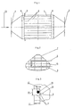
- the device for aftertreatment illustrated in FIG. 1 of diesel exhaust consists of a housing 1 with a Exhaust gas inlet 2 and an exhaust gas outlet 3, one ceramic filter body 4 and an exhaust gas inlet side arranged heating element 5.
- the filter body 4 is made of several cuboidal sub-elements 6 put together.
- the joints 15 can by High temperature adhesive are produced.
- On the outside The surface is the contour 7 of the filter body 4 on the housing 1 adapted, as shown schematically in Fig. 2 and Fig. 4 is clear.
- groove-like depressions 9 are incorporated, which are performed so that the majority of the sub-elements 6 adjoin the recess 9 or directly from you are crossed.
- the heating element 5 is designed as a heating wire 16.
- the heating wire 16 can consist of several Single wires, strands, be joined together. Width 10 and depth 11 of the groove-like recess 9 are greater than the diameter 12 of the heating wire 16, as shown in FIG. 3 is shown.
- the arrangement of the heating wire 16 in the groove-shaped recess 9 takes place in such a way that the smallest possible contact area between the surface of the heating wire 16 and the Surface 17 of the groove-like recess 9 is formed.
- the Heating wire 16 is fastened in the grooves by means of clips 14.
- the bracket 14 made of ceramic material.
- the heating element 5 is designed as a point heater 20.
- the groove-like recess 9 are several over a common one Supply line fed point heater 20 arranged.
- the fastening element forms 21 with the point heater 20 a unit.
- the Fastening element 21 is preferably made of ceramic Material.
- Fig. 5 shows a unit consisting of point heater 20 with fastener 21 in the groove-like recess 9.
Landscapes
- Engineering & Computer Science (AREA)
- Chemical & Material Sciences (AREA)
- Combustion & Propulsion (AREA)
- Mechanical Engineering (AREA)
- General Engineering & Computer Science (AREA)
- Processes For Solid Components From Exhaust (AREA)
Description
- kontinuierlicher Oxidation der freischwebenden Partikel im Abgas
- Abgaskatalysatoren
- Trägheitskraftabscheidern
- Naßabscheideverfahren
- elektrostatischen Abscheidern
- Partikelsammlung und diskontinuierlicher Filterregeneration
- Erhöhung der Abgastemperatur durch motorische Maßnahmen,
- Erhöhung der Abgastemperatur durch Sekundärenergie,
- direktes Entflammen der Rußschicht durch Sekundärenergie,
- Senkung der Rußzündtemperatur durch Katalysatoren oder chemische Zündhilfen.
- Fig. 1
- eine erste Ausführungsform einer erfindungsgemäßen Vorrichtung zur Nachbehandlung von Dieselabgasen im Längsschnitt,
- Fig. 2
- eine Draufsicht auf die eintrittsseitige Stirnfläche des keramischen Filterkörpers der Vorrichtung nach Fig. 1 mit Heizdraht,
- Fig. 3
- einen Querschnitt durch eine Nut mit Heizdraht und Halteklammer,
- Fig. 4
- in Draufsicht die eintrittsseitige Stirnfläche des keramischen Filterkörpers eines zweiten Ausführungsbeispiels der erfindungsgemäßen Vorrichtung mit Punktheizer und
- Fig. 5
- einen Querschnitt durch eine Nut mit Punktheizer.
Claims (11)
- Vorrichtung zur Nachbehandlung von Dieselabgasen, insbesondere zur Entfernung von Rußpartikeln, mit kontinuierlicher Filtration und diskontinuierlicher Regeneration, mit einem abgasdurchströmten Gehäuse (1) und einem im Abgasstrom angeordneten Filterkörper (4), dem anströmseitig mindestens ein elektrisches Heizelement (5) in Form eines langgestreckten Heizers zugeordnet ist und dessen stromeintrittsseitige Oberfläche (8) mindestens eine nutartige Vertiefung (9) aufweist,
dadurch gekennzeichnet, daß die nutartige Vertiefung (9) entgegen der Anströmrichtung offen ist und daß das mindestens eine Heizelement (5) dergestalt in die nutartige Vertiefung (9) eingebettet ist, daß es sie in ihrer Länge ausfüllt. - Vorrichtung nach Anspruch 1,
dadurch gekennzeichnet, daß Nutbreite (10) und/oder Nuttiefe (11) größer als die Breite (17) und/oder die Tiefe (12) des mindestens einen Heizelementes (5) sind. - Vorrichtung nach einem der Ansprüche 1 oder 2,
dadurch gekennzeichnet, daß der Filterkörper (4) als keramischer Monolith ausgebildet ist. - Vorrichtung nach einem der Ansprüche 1 bis 3,
dadurch gekennzeichnet, daß das mindestens eine Heizelement (5) mit Befestigungselementen (14, 21) in der nutförmigen Vertiefung (9) arretiert ist. - Vorrichtung nach Anspruch 4,
dadurch gekennzeichnet, daß die Befestigungselemente (14) als Halteklammern ausgebildet sind. - Vorrichtung nach Anspruch 4 oder Anspruch 5,
dadurch gekennzeichnet, daß die Befestigungselemente (21, 14) aus keramischem Material bestehen. - Vorrichtung nach einem der Ansprüche 1 bis 6,
dadurch gekennzeichnet, daß das mindestens eine Heizelement (5) als Heizdraht (16) ausgebildet ist. - Vorrichtung nach Anspruch 7,
dadurch gekennzeichnet, daß der mindestens eine Heizer mit Befestigungselementen (14, 21) in der nutförmigen Vertiefung (9) arretiert ist, wobei mindestens 90% der Oberfläche des mindestens einen Heizers freiliegen. - Vorrichtung nach Anspruch 7 oder Anspruch 8,
dadurch gekennzeichnet, daß der mindestens eine Heizer als ein aus mehreren Litzen bestehender Heizdraht (16) ausgeführt ist. - Vorrichtung nach einem der Ansprüche 1 bis 9,
dadurch gekennzeichnet, daß der Filterkörper (4) aus einer Mehrzahl quaderförmiger Teilelemente (6) besteht, wobei die mindestens eine nutförmige Vertiefung (9) in der stromeintrittsseitigen Oberfläche (8) des Filterkörpers (4) so angeordnet ist, daß die Mehrzahl der quaderförmigen Teilelemente (6) an die nutförmige Vertiefung (9) angrenzen und/oder direkt mit ihr versehen sind. - Vorrichtung nach einem der Ansprüche 1 bis 10,
dadurch gekennzeichnet, daß die an die mindestens eine nutartige Vertiefung angrenzenden Filterkanäle des Filterkörpers (4) zuströmseitig verschlossen sind.
Applications Claiming Priority (2)
| Application Number | Priority Date | Filing Date | Title |
|---|---|---|---|
| DE10029978 | 2000-06-26 | ||
| DE10029978A DE10029978A1 (de) | 2000-06-26 | 2000-06-26 | Vorrichtung zur Nachbehandlung von Dieselabgasen |
Publications (3)
| Publication Number | Publication Date |
|---|---|
| EP1167708A2 EP1167708A2 (de) | 2002-01-02 |
| EP1167708A3 EP1167708A3 (de) | 2003-08-13 |
| EP1167708B1 true EP1167708B1 (de) | 2004-11-10 |
Family
ID=7646156
Family Applications (1)
| Application Number | Title | Priority Date | Filing Date |
|---|---|---|---|
| EP01115227A Expired - Lifetime EP1167708B1 (de) | 2000-06-26 | 2001-06-22 | Vorrichtung zur Nachbehandlung von Dieselabgasen |
Country Status (2)
| Country | Link |
|---|---|
| EP (1) | EP1167708B1 (de) |
| DE (2) | DE10029978A1 (de) |
Families Citing this family (2)
| Publication number | Priority date | Publication date | Assignee | Title |
|---|---|---|---|---|
| US8763378B2 (en) | 2007-06-15 | 2014-07-01 | GM Global Technology Operations LLC | Electrically heated particulate filter embedded heater design |
| DE102008039589B4 (de) * | 2007-10-22 | 2013-05-29 | GM Global Technology Operations LLC (n. d. Ges. d. Staates Delaware) | Auslegung eines elektrisch beheizten Katalysators mit eingebetteter Heizvorrichtung |
Family Cites Families (15)
| Publication number | Priority date | Publication date | Assignee | Title |
|---|---|---|---|---|
| JPS578311A (en) * | 1980-06-19 | 1982-01-16 | Toyota Motor Corp | Method and device for decreasing discharged quantity of diesel particulates |
| US4456457A (en) * | 1981-04-28 | 1984-06-26 | Nippon Soken, Inc. | Exhaust gas cleaning device for diesel engine |
| JPS58210310A (ja) * | 1982-06-01 | 1983-12-07 | Nippon Denso Co Ltd | 内燃機関のカ−ボン微粒子浄化装置 |
| EP0233860B1 (de) * | 1986-02-19 | 1991-05-15 | BÖHLER Gesellschaft m.b.H. | Abgasreinigungseinrichtung |
| US4744216A (en) * | 1986-10-20 | 1988-05-17 | Ford Motor Company | Electrical ignition device for regeneration of a particulate trap |
| DE8700787U1 (de) * | 1987-01-17 | 1987-10-22 | Gürtler, Johann, 6074 Rödermark | Rußfilter für Dieselmotoren |
| DE3712333A1 (de) * | 1987-04-11 | 1988-10-20 | Fev Motorentech Gmbh & Co Kg | Regenerierbare filteranordnung zum entfernen von russpartikeln aus abgasen |
| DE3890556C2 (de) | 1987-07-02 | 1993-01-07 | Mitsubishi Jidosha Kogyo K.K., Tokio/Tokyo, Jp | |
| KR930000473B1 (ko) | 1987-07-20 | 1993-01-21 | 미쯔비시지도오샤고오교오 가부시기가이샤 | 디이젤엔진의 배기정화장치 |
| US5101095A (en) * | 1989-03-30 | 1992-03-31 | Donaldson Company, Inc. | Diesel engine gas filter with electrical heater |
| JPH04179818A (ja) * | 1990-11-14 | 1992-06-26 | Nippon Soken Inc | 排気ガス微粒子浄化装置 |
| JPH06257422A (ja) * | 1993-01-06 | 1994-09-13 | Sumitomo Electric Ind Ltd | ディーゼルエンジン用パティキュレートトラップ |
| JPH08229330A (ja) * | 1995-02-28 | 1996-09-10 | Sumitomo Electric Ind Ltd | ディーゼルエンジン用パティキュレートトラップ |
| DE19530749A1 (de) * | 1995-08-22 | 1997-03-06 | Hjs Fahrzeugtechnik Gmbh & Co | Vorrichtung zum Entfernen von Rußpartikeln aus Abgasen |
| DE19748561A1 (de) * | 1997-11-04 | 1999-05-06 | Htw Dresden | Verfahren und Vorrichtung zur Regeneration von Partikelfiltern in Dieselmotor-Abgasanlagen |
-
2000
- 2000-06-26 DE DE10029978A patent/DE10029978A1/de not_active Withdrawn
-
2001
- 2001-06-22 EP EP01115227A patent/EP1167708B1/de not_active Expired - Lifetime
- 2001-06-22 DE DE50104456T patent/DE50104456D1/de not_active Expired - Fee Related
Also Published As
| Publication number | Publication date |
|---|---|
| DE50104456D1 (de) | 2004-12-16 |
| EP1167708A3 (de) | 2003-08-13 |
| DE10029978A1 (de) | 2002-01-10 |
| EP1167708A2 (de) | 2002-01-02 |
Similar Documents
| Publication | Publication Date | Title |
|---|---|---|
| DE69402437T2 (de) | Partikelabscheider | |
| DE69116644T2 (de) | Regenerierbare Partikelfilteranlage zur Emissionskontrolle | |
| DE69610022T2 (de) | Partikelfalle für einen Dieselmotor | |
| DE4342652B4 (de) | Honigwabenförmige Heizeinrichtung | |
| WO2001020142A1 (de) | Vorrichtung mit heizelement zur abgasreinigung | |
| EP3652420B1 (de) | System und verfahren zur abgasnachbehandlung eines verbrennungsmotors | |
| EP0892887A1 (de) | Hitzebeständiger und regenerierbarer filterkörper mit strömungswegen | |
| EP1440226A1 (de) | Offener partikelfilter mit heizelement | |
| EP1328711B1 (de) | Beheizbarer wabenkörper mit zwei verschiedenen beschichtungen | |
| DE20016803U1 (de) | Filtereinrichtung | |
| EP0585432B1 (de) | Filteranordnung zum entfernen von russpartikeln aus abgasen einer verbrennungskraftmaschine | |
| EP3134622B1 (de) | Baukastensystem für die baugruppe, und verfahren zur herstellung der baugruppe | |
| EP1379322A1 (de) | Abgassystem | |
| DE102019101679A1 (de) | Abgasheizelement | |
| DE2501241A1 (de) | Fluidbehandlungsstruktur | |
| DE69920995T2 (de) | Heizvorrichtung für einen Abgasreinigungskatalysator | |
| EP0329818A2 (de) | Elektrostatischer Dieselpartikelfilter | |
| EP1167708B1 (de) | Vorrichtung zur Nachbehandlung von Dieselabgasen | |
| EP0677141B1 (de) | Katalysator | |
| DE102009014371A1 (de) | Beheizbarer Vorfilter für Abgasreinigungsanlagen bei Dieselmotoren | |
| DE60207174T2 (de) | Kegelförmige Enden für Vorrichtungen zur Abgasemissionssteuerung und Verfahren zur Herstellung | |
| DE4303586A1 (en) | Exhaust emission controller for IC engine - has tubular filter elements with regenerative heaters embedded in thickened walls and mounted in tubular housing | |
| DE60210557T2 (de) | Vorrichtung zur Abgasbehandlung einer Brennkraftmaschine | |
| DE60206796T2 (de) | Filtervorrichtung für dieselmotoren-abgase mit einem integrierten katalytischen trägermaterial | |
| EP2151551B1 (de) | Abgasnachbehandlungselement zur Entfernung von Schadstoffen und/oder Partikeln aus dem Abgas einer Brennkraftmfaschine |
Legal Events
| Date | Code | Title | Description |
|---|---|---|---|
| PUAI | Public reference made under article 153(3) epc to a published international application that has entered the european phase |
Free format text: ORIGINAL CODE: 0009012 |
|
| AK | Designated contracting states |
Kind code of ref document: A2 Designated state(s): AT BE CH CY DE DK ES FI FR GB GR IE IT LI LU MC NL PT SE TR |
|
| AX | Request for extension of the european patent |
Free format text: AL;LT;LV;MK;RO;SI |
|
| PUAL | Search report despatched |
Free format text: ORIGINAL CODE: 0009013 |
|
| AK | Designated contracting states |
Designated state(s): AT BE CH CY DE DK ES FI FR GB GR IE IT LI LU MC NL PT SE TR |
|
| AX | Request for extension of the european patent |
Extension state: AL LT LV MK RO SI |
|
| RIC1 | Information provided on ipc code assigned before grant |
Ipc: 7B 01D 46/42 B Ipc: 7F 01N 3/023 B Ipc: 7F 01N 3/28 B Ipc: 7F 01N 3/027 A |
|
| 17P | Request for examination filed |
Effective date: 20031022 |
|
| 17Q | First examination report despatched |
Effective date: 20031208 |
|
| GRAP | Despatch of communication of intention to grant a patent |
Free format text: ORIGINAL CODE: EPIDOSNIGR1 |
|
| AKX | Designation fees paid |
Designated state(s): DE FR |
|
| GRAS | Grant fee paid |
Free format text: ORIGINAL CODE: EPIDOSNIGR3 |
|
| GRAA | (expected) grant |
Free format text: ORIGINAL CODE: 0009210 |
|
| AK | Designated contracting states |
Kind code of ref document: B1 Designated state(s): DE FR |
|
| REG | Reference to a national code |
Ref country code: IE Ref legal event code: FG4D Free format text: GERMAN |
|
| REF | Corresponds to: |
Ref document number: 50104456 Country of ref document: DE Date of ref document: 20041216 Kind code of ref document: P |
|
| RAP2 | Party data changed (patent owner data changed or rights of a patent transferred) |
Owner name: ARVINMERITOR EMISSIONS TECHNOLOGIES GMBH |
|
| PLBE | No opposition filed within time limit |
Free format text: ORIGINAL CODE: 0009261 |
|
| STAA | Information on the status of an ep patent application or granted ep patent |
Free format text: STATUS: NO OPPOSITION FILED WITHIN TIME LIMIT |
|
| ET | Fr: translation filed | ||
| 26N | No opposition filed |
Effective date: 20050811 |
|
| PG25 | Lapsed in a contracting state [announced via postgrant information from national office to epo] |
Ref country code: DE Free format text: LAPSE BECAUSE OF NON-PAYMENT OF DUE FEES Effective date: 20060103 |
|
| PG25 | Lapsed in a contracting state [announced via postgrant information from national office to epo] |
Ref country code: FR Free format text: LAPSE BECAUSE OF NON-PAYMENT OF DUE FEES Effective date: 20060228 |
|
| REG | Reference to a national code |
Ref country code: FR Ref legal event code: ST Effective date: 20060228 |