EP1167721A2 - Procédé et dispositif de refroidissement d'une turbine a gaz - Google Patents
Procédé et dispositif de refroidissement d'une turbine a gaz Download PDFInfo
- Publication number
- EP1167721A2 EP1167721A2 EP01112664A EP01112664A EP1167721A2 EP 1167721 A2 EP1167721 A2 EP 1167721A2 EP 01112664 A EP01112664 A EP 01112664A EP 01112664 A EP01112664 A EP 01112664A EP 1167721 A2 EP1167721 A2 EP 1167721A2
- Authority
- EP
- European Patent Office
- Prior art keywords
- cooling
- compressor
- air
- turbine
- gas turbine
- Prior art date
- Legal status (The legal status is an assumption and is not a legal conclusion. Google has not performed a legal analysis and makes no representation as to the accuracy of the status listed.)
- Granted
Links
Images


Classifications
-
- F—MECHANICAL ENGINEERING; LIGHTING; HEATING; WEAPONS; BLASTING
- F01—MACHINES OR ENGINES IN GENERAL; ENGINE PLANTS IN GENERAL; STEAM ENGINES
- F01D—NON-POSITIVE DISPLACEMENT MACHINES OR ENGINES, e.g. STEAM TURBINES
- F01D5/00—Blades; Blade-carrying members; Heating, heat-insulating, cooling or antivibration means on the blades or the members
- F01D5/12—Blades
- F01D5/14—Form or construction
- F01D5/18—Hollow blades, i.e. blades with cooling or heating channels or cavities; Heating, heat-insulating or cooling means on blades
- F01D5/187—Convection cooling
-
- F—MECHANICAL ENGINEERING; LIGHTING; HEATING; WEAPONS; BLASTING
- F02—COMBUSTION ENGINES; HOT-GAS OR COMBUSTION-PRODUCT ENGINE PLANTS
- F02C—GAS-TURBINE PLANTS; AIR INTAKES FOR JET-PROPULSION PLANTS; CONTROLLING FUEL SUPPLY IN AIR-BREATHING JET-PROPULSION PLANTS
- F02C7/00—Features, components parts, details or accessories, not provided for in, or of interest apart form groups F02C1/00 - F02C6/00; Air intakes for jet-propulsion plants
- F02C7/12—Cooling of plants
- F02C7/16—Cooling of plants characterised by cooling medium
- F02C7/18—Cooling of plants characterised by cooling medium the medium being gaseous, e.g. air
- F02C7/185—Cooling means for reducing the temperature of the cooling air or gas
-
- F—MECHANICAL ENGINEERING; LIGHTING; HEATING; WEAPONS; BLASTING
- F05—INDEXING SCHEMES RELATING TO ENGINES OR PUMPS IN VARIOUS SUBCLASSES OF CLASSES F01-F04
- F05D—INDEXING SCHEME FOR ASPECTS RELATING TO NON-POSITIVE-DISPLACEMENT MACHINES OR ENGINES, GAS-TURBINES OR JET-PROPULSION PLANTS
- F05D2260/00—Function
- F05D2260/20—Heat transfer, e.g. cooling
- F05D2260/202—Heat transfer, e.g. cooling by film cooling
-
- F—MECHANICAL ENGINEERING; LIGHTING; HEATING; WEAPONS; BLASTING
- F05—INDEXING SCHEMES RELATING TO ENGINES OR PUMPS IN VARIOUS SUBCLASSES OF CLASSES F01-F04
- F05D—INDEXING SCHEME FOR ASPECTS RELATING TO NON-POSITIVE-DISPLACEMENT MACHINES OR ENGINES, GAS-TURBINES OR JET-PROPULSION PLANTS
- F05D2260/00—Function
- F05D2260/20—Heat transfer, e.g. cooling
- F05D2260/205—Cooling fluid recirculation, i.e. after cooling one or more components is the cooling fluid recovered and used elsewhere for other purposes
Definitions
- the present invention relates to the field of gas turbines. It affects a method for cooling a gas turbine according to the preamble of the claim 1 and a gas turbine plant according to the preamble of the claim 13 to carry out the method.
- Such a method and such a gas turbine plant are e.g. B. from the Document US-A-5,611,197 known.
- the first category has the disadvantage that the cooling fluid, which is the heating inherently in the combustion chamber, usually a higher one in the cooling section Pressure drop occurs when it is necessary for the cooling task.
- mixing losses generated when the cooling fluid enters the main flow Both are significant Process losses that significantly affect the efficiency of the overall process affect.
- the second category of externally supplied closed cooling systems and the third category of combined cooling systems in particular also has these disadvantages either not or only to a limited extent, but the operation is instead carried out by an external one Coolant supply dependent, which increased complexity, as well as increased Costs and security risks.
- the object is achieved by the entirety of the features of claims 1 and 13.
- the essence of the invention is to use a compressor that includes closed cooling air circuit starting from the cooled component to branch off a small part of the cooling air in the manner of a targeted leakage and to be released to the outside through appropriate film cooling holes, without any significant Impairment of the efficiency of effective film cooling to enable the hot gas-contaminated outer surface of the component.
- the thermally loaded components cooled by means of the cooling air comprise the walls of the combustion chamber and / or housing parts of the turbine and / or Rotor parts of the turbine and / or blades of the turbine.
- a preferred embodiment of the method according to the invention is thereby characterized in that the blades of the turbine are cooled by means of the cooling air and that the film cooling holes on the blade leading edges and / or the blade trailing edges are arranged. This will result in a low Loss of cooling air effectively affects the particularly heavily loaded edges of the blades film-cooled.
- the turbine comprises a plurality of rows of blades, and the rows of blades are successively flowed through by the cooling air.
- the cooling air suffers a pressure loss during the cooling process, which occurs before the return the cooling air must be compensated for by compression. This can be done with particularly little effort if according to another embodiment of the inventive method for compressing the cooling air used after the cooling process of the compressor of the gas turbine system itself is, i.e. when the cooling air is fed into the compressor at a medium pressure level becomes.
- an external compressor can be used. Then the cooling air by means of external compressor compressed to the pressure of the compressor end air, the compressed Cooling air can be added directly to the compressor end air.
- the cooling air is preferably cooled after the cooling process and before compression.
- the compressor end temperature in particular can be adjusted be lowered. This allows an increase in the pressure ratio and thus the efficiency.
- a cooler can be used to cool the cooling air. But it is it is also conceivable that water is injected directly into the cooling air to cool the cooling air becomes. It is also possible to use the cooling air with a heat exchanger to cool the compressor end air, preferably the cooling air after passing through the heat exchanger is cooled even further by means of another cooling medium becomes.
- a preferred embodiment of the gas turbine system according to the invention thereby characterized in that the second cooling lines in the compressor on a middle pressure stage open.
- an external compressor can be arranged, the second cooling lines in the Output of the compressor of the gas turbine system open.
- Another preferred embodiment is characterized in that in the a cooler is arranged in the second cooling lines.
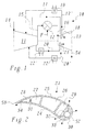
- the gas turbine system 10 comprises one (usually multi-stage) compressor 11, a combustion chamber 12 and a (usually multi-stage) turbine 13.
- Compressor 11 and turbine 13 have corresponding Row of blades arranged on a common rotor.
- the compressor 11 sucks in intake air 14 on the inlet side, compresses it and releases it on the outlet side in the form of compressor end air 15 to the combustion chamber 12, where it as combustion air for the combustion of a (liquid or gaseous) Fuel F is used.
- the hot gas generated during combustion 16 is relaxed in the subsequent turbine 13 under work finally as flue gas 54 to a chimney or - in a combined cycle power plant - to one downstream heat recovery steam generator forwarded.
- the thermally loaded components are now cooled with cooling air, taken from the compressor 11 at a predetermined pressure level, led to the component to be cooled via a first cooling line 17 or 20, used there for cooling and then predominantly via a second cooling line 17 'or 20' returned to the compressor 11 and there on a lower pressure level is fed back.
- the compressor 11 can be the result of the cooling process Compensate for pressure loss.
- the cooling air therefore takes up a large part as combustion air in the combustion process part and therefore leads to only minor Efficiency losses.
- the cooling of the thermally stressed components is predominantly internal cooling, in which the cooling air passes through inside the components provided cooling channels flows. The result is a largely closed one Cooling circuit.
- the cooling circuit is not completely closed, but provides for additional external cooling in the form of film cooling.
- the component to be cooled is provided with outflow openings (film cooling holes), through which a small part of the circulating cooling air as leakage air 18 or 21 flows outwards and on the hot gas-contaminated outer surface of the component forms a cooling film.
- the proportion of leakage air 18, 21 is chosen so that on the one hand the overall efficiency of the system is only slightly reduced on the other hand, effective film cooling is achieved.
- FIG. 1 In the example in FIG. 1, two such cooling circuits (17, 17 ', 18 and 20, 20', 21) are shown, which - as required - at different pressure levels of the compressor 11 Remove cooling air and feed it back in.
- the heat absorbed by the cooling air during the cooling process can now removed from the cooling air before being fed back into the compressor 11 that a cooler 19 or 22 is arranged.
- the cooling medium in the coolers 19, 22 comes e.g. Consider water or steam. But it is just as possible, in addition to or instead of this recooling, the compressed air after removal the compressor 11 - e.g. by means of a cooler 22 '- to a lower temperature cool before it is used to cool thermally stressed components.
- the recooling of the cooling air by means of the coolers 19, 22 can be used simultaneously are, the temperature of the air compressed in the compressor 11 according to Art of an intercooler.
- the cooling air in the coolers 19, 22 becomes essential recooled more than the heat absorbed during the cooling process, the compressor end temperature, i.e. the temperature of the compressor end air 15 are lowered, which is an increase in the pressure ratio and thus enabling an increase in efficiency.
- a suitable exemplary blade 23 is in cross section shown in Fig. 2.
- the blade 23 has a blade wall on the pressure side 24 and a suction-side blade wall 25, each of which is located on the blade leading edge 52 and combine at the blade leading edge 53.
- Inside the shovel 23 are - separated from one another by supporting walls - different cooling channels 26, .., 30 arranged in the axial direction of the blade 23 (i.e. perpendicular to the plane of the drawing) run and the cooling air flows in alternating directions (see e.g. EP-A2-0 899 425).
- cooling channels 28 and 30 follow film cooling holes 33 and 34, respectively outside, through which the leakage air flows out and one on the outside Can form cooling film (see e.g. also US-A-5,498,133).
- the cooling channels 28, 30 are from the adjacent cooling channels 27, 29 through connecting channels 31, 32 supplied with cooling air.
- cooling can be implemented in different variants that are tailored to different applications and their special Have advantages.
- a gas turbine system 35 two of these variants are realized.
- the cooling circuit shown here which through the cooling lines 37 and 37 'is formed, the cooling air is branched off directly from the compressor end air 15 and the compressor end air 15 also added again.
- the necessary recompression is therefore not made in the compressor 11 of the gas turbine system 35, but instead by means of an external compressor 36.
- there is pre-cooling a cooler 19 is provided for recompression.
- the cooling circuit is at this Example not only used for a single row of blades of the turbine 13, but for multiple rows of blades 38, 39 and 40, sequentially by the cooling air be flowed through. In each of the rows of blades 38, .., 40 flows for film cooling the edges corresponding to leakage air into the main flow of the turbine 13.
- FIG. 4 Another exemplary embodiment of the cooling according to the invention is shown in FIG. 4 shown.
- a heat exchanger 43 is placed in the second cooling line 42 ′ inserted, (in counterflow) from the cooling air and the compressor end air 15 is flowed through. If this first recooling in the heat exchanger 43 is not sufficient off, an additional cooler 44 can be connected downstream, which acts as a cooling medium for example water or steam used.
- FIG. 5 Another possibility of recooling is in the exemplary embodiment in FIG. 5 shown.
- an injection device 47 is inserted into the cooling lines 46, 46 ', in which after Kind of a "quench cooling” water is injected or injected into the cooling air.
- the temperature reduction of the cooling air that can be achieved in this way is preferably so designed that after mixing the recooled cooling air with the through the compressor 11 flowing main air reduces the temperature of the mixed gas becomes. As already mentioned above, this gives the possibility of efficiency to increase the plant.
- Cooling circuit with the cooling lines 49, 49 'and the cooler 51 are designed to cover the walls of the combustion chamber 12 or the combustion chamber liner through internal cooling air circulation and external film cooling to cool.
- Another cooling circuit shown in dashed lines with the Cooling lines 50, 50 'ensure internal and external cooling of the hot gas housing the turbine 13, in particular in the entry area of the hot gases.
- the invention results in effective thermal cooling loaded components of a gas turbine system that is simply constructed and operated can be used flexibly and have little impact on the overall efficiency of the system.
Landscapes
- Engineering & Computer Science (AREA)
- Mechanical Engineering (AREA)
- General Engineering & Computer Science (AREA)
- Chemical & Material Sciences (AREA)
- Combustion & Propulsion (AREA)
- Turbine Rotor Nozzle Sealing (AREA)
- Structures Of Non-Positive Displacement Pumps (AREA)
Applications Claiming Priority (2)
| Application Number | Priority Date | Filing Date | Title |
|---|---|---|---|
| DE10027842A DE10027842A1 (de) | 2000-06-05 | 2000-06-05 | Verfahren zum Kühlen einer Gasturbinenanlage sowie Gasturbinenanlage zur Durchführung des Verfahrens |
| DE10027842 | 2000-06-05 |
Publications (3)
| Publication Number | Publication Date |
|---|---|
| EP1167721A2 true EP1167721A2 (fr) | 2002-01-02 |
| EP1167721A3 EP1167721A3 (fr) | 2004-06-09 |
| EP1167721B1 EP1167721B1 (fr) | 2006-06-28 |
Family
ID=7644777
Family Applications (1)
| Application Number | Title | Priority Date | Filing Date |
|---|---|---|---|
| EP01112664A Expired - Lifetime EP1167721B1 (fr) | 2000-06-05 | 2001-05-25 | Procédé et dispositif de refroidissement d'une turbine a gaz |
Country Status (3)
| Country | Link |
|---|---|
| US (1) | US7263834B2 (fr) |
| EP (1) | EP1167721B1 (fr) |
| DE (2) | DE10027842A1 (fr) |
Cited By (2)
| Publication number | Priority date | Publication date | Assignee | Title |
|---|---|---|---|---|
| WO2003033890A1 (fr) * | 2001-10-17 | 2003-04-24 | Alstom Technology Ltd | Procede de conditionnement d'un flux d'air de compresseur et dispositif permettant la mise en oeuvre dudit procede |
| CH705181A1 (de) * | 2011-06-16 | 2012-12-31 | Alstom Technology Ltd | Verfahren zum Kühlen einer Gasturbinenanlage sowie Gasturbinenanlage zur Durchführung des Verfahrens. |
Families Citing this family (9)
| Publication number | Priority date | Publication date | Assignee | Title |
|---|---|---|---|---|
| DE102007026455A1 (de) * | 2007-06-05 | 2008-12-11 | Rolls-Royce Deutschland Ltd & Co Kg | Strahltriebwerk mit Verdichterluftzirkulation und Verfahren zum Betreiben desselben |
| US20090056342A1 (en) * | 2007-09-04 | 2009-03-05 | General Electric Company | Methods and Systems for Gas Turbine Part-Load Operating Conditions |
| JP5787838B2 (ja) * | 2011-07-27 | 2015-09-30 | アルストム テクノロジー リミテッドALSTOM Technology Ltd | 排気ガス再循環を備えるガスタービン発電プラント及びその作動方法 |
| WO2015122949A2 (fr) * | 2013-12-17 | 2015-08-20 | United Technologies Corporation | Système de refroidissement de turbomachine adaptatif |
| JP6296286B2 (ja) | 2014-03-24 | 2018-03-20 | 三菱日立パワーシステムズ株式会社 | 排熱回収システム、これを備えているガスタービンプラント、排熱回収方法、及び排熱回収システムの追設方法 |
| US10119471B2 (en) | 2015-10-09 | 2018-11-06 | General Electric Company | Turbine engine assembly and method of operating thereof |
| US10156142B2 (en) * | 2015-11-24 | 2018-12-18 | General Electric Company | Systems and methods for producing one or more cooling holes in an airfoil for a gas turbine engine |
| US10036325B2 (en) * | 2016-03-30 | 2018-07-31 | General Electric Company | Variable flow compressor of a gas turbine |
| US11300051B2 (en) | 2019-02-01 | 2022-04-12 | Honeywell International Inc. | Engine systems with load compressor that provides cooling air |
Family Cites Families (21)
| Publication number | Priority date | Publication date | Assignee | Title |
|---|---|---|---|---|
| US3571909A (en) * | 1968-12-30 | 1971-03-23 | Croft Metal Products Inc | Method of joining structural members of a ladder |
| DE2042478C3 (de) * | 1970-08-27 | 1975-08-14 | Motoren- Und Turbinen-Union Muenchen Gmbh, 8000 Muenchen | Gasturbinentriebwerk, vorzugsweise Strahltriebwerk für Flugzeuge, mit Kühlluft- und gegebenenfalls Sperrluftentnahme |
| JP3142850B2 (ja) * | 1989-03-13 | 2001-03-07 | 株式会社東芝 | タービンの冷却翼および複合発電プラント |
| US5405242A (en) * | 1990-07-09 | 1995-04-11 | United Technologies Corporation | Cooled vane |
| US5134844A (en) * | 1990-07-30 | 1992-08-04 | General Electric Company | Aft entry cooling system and method for an aircraft engine |
| US5498133A (en) | 1995-06-06 | 1996-03-12 | General Electric Company | Pressure regulated film cooling |
| JPH096531A (ja) * | 1995-06-20 | 1997-01-10 | Casio Comput Co Ltd | ポインティングデバイス及びその制御システム |
| US5581996A (en) * | 1995-08-16 | 1996-12-10 | General Electric Company | Method and apparatus for turbine cooling |
| US5611197A (en) * | 1995-10-23 | 1997-03-18 | General Electric Company | Closed-circuit air cooled turbine |
| DE19546726A1 (de) * | 1995-12-14 | 1997-06-19 | Asea Brown Boveri | Quench-Kühler |
| US6098395A (en) * | 1996-04-04 | 2000-08-08 | Siemens Westinghouse Power Corporation | Closed-loop air cooling system for a turbine engine |
| US5782076A (en) * | 1996-05-17 | 1998-07-21 | Westinghouse Electric Corporation | Closed loop air cooling system for combustion turbines |
| JP2001504564A (ja) * | 1996-09-26 | 2001-04-03 | シーメンス アクチエンゲゼルシヤフト | ガスタービン設備において冷却空気の案内により生ずる圧力損失の補償方法 |
| DE19737845C2 (de) * | 1997-08-29 | 1999-12-02 | Siemens Ag | Verfahren zum Herstellen einer Gasturbinenschaufel, sowie nach dem Verfahren hergestellte Gasturbinenschaufel |
| DE19738065A1 (de) | 1997-09-01 | 1999-03-04 | Asea Brown Boveri | Turbinenschaufel einer Gasturbine |
| JPH1193694A (ja) * | 1997-09-18 | 1999-04-06 | Toshiba Corp | ガスタービンプラント |
| US6065282A (en) * | 1997-10-29 | 2000-05-23 | Mitsubishi Heavy Industries, Ltd. | System for cooling blades in a gas turbine |
| DE19832767A1 (de) * | 1998-07-22 | 2000-01-27 | Siemens Ag | Vorrichtung sowie Verfahren zur Reinigung eines hohlen Bauteils einer Strömungsmaschine |
| US6183198B1 (en) * | 1998-11-16 | 2001-02-06 | General Electric Company | Airfoil isolated leading edge cooling |
| US6506013B1 (en) * | 2000-04-28 | 2003-01-14 | General Electric Company | Film cooling for a closed loop cooled airfoil |
| DE10027833A1 (de) * | 2000-06-05 | 2001-12-13 | Alstom Power Nv | Verfahren zum Kühlen einer Gasturbinenanlage sowie Gasturbinenanlage zur Durchführung des Verfahrens |
-
2000
- 2000-06-05 DE DE10027842A patent/DE10027842A1/de not_active Withdrawn
-
2001
- 2001-05-25 EP EP01112664A patent/EP1167721B1/fr not_active Expired - Lifetime
- 2001-05-25 DE DE50110311T patent/DE50110311D1/de not_active Expired - Lifetime
- 2001-06-05 US US09/873,373 patent/US7263834B2/en not_active Expired - Fee Related
Cited By (3)
| Publication number | Priority date | Publication date | Assignee | Title |
|---|---|---|---|---|
| WO2003033890A1 (fr) * | 2001-10-17 | 2003-04-24 | Alstom Technology Ltd | Procede de conditionnement d'un flux d'air de compresseur et dispositif permettant la mise en oeuvre dudit procede |
| CH705181A1 (de) * | 2011-06-16 | 2012-12-31 | Alstom Technology Ltd | Verfahren zum Kühlen einer Gasturbinenanlage sowie Gasturbinenanlage zur Durchführung des Verfahrens. |
| US9145774B2 (en) | 2011-06-16 | 2015-09-29 | Alstom Technology Ltd. | Method for cooling a gas turbine plant and gas turbine plant for implementing the method |
Also Published As
| Publication number | Publication date |
|---|---|
| DE50110311D1 (de) | 2006-08-10 |
| EP1167721A3 (fr) | 2004-06-09 |
| DE10027842A1 (de) | 2001-12-20 |
| EP1167721B1 (fr) | 2006-06-28 |
| US7263834B2 (en) | 2007-09-04 |
| US20040206064A1 (en) | 2004-10-21 |
Similar Documents
| Publication | Publication Date | Title |
|---|---|---|
| EP1162355B1 (fr) | Méthode de refroidissement d'une turbine à gaz et turbine à gaz correspondante | |
| DE102012011294B4 (de) | Verfahren zum Kühlen einer Gasturbinenanlage sowie Gasturbinenanlage zur Durchführung des Verfahrens | |
| DE69715393T2 (de) | Geschlossenes luftkühlungssystem für eine gasturbine | |
| EP0953748B1 (fr) | Centrale d'énergie avec un cycle de CO2 | |
| DE68907191T2 (de) | Verfahren und vorrichtung zum optimieren der temperatur der von einer gasturbine angesaugten luft. | |
| EP0851104B1 (fr) | Turbine à gaz avec générateur de vapeur à récupération pour le refroidissement de la chambre de combustion, puis l'injection en aval de la zone de combustion | |
| EP0563520B1 (fr) | Installation de turbine à gaz | |
| DE2835903A1 (de) | Kuehlluft-kuehler fuer ein gasturbinentriebwerk | |
| WO2001065095A1 (fr) | Systeme d'air de refroidissement | |
| DE10312971B4 (de) | Verfahren zum Betreiben einer Gasturbogruppe | |
| DE102006024315A1 (de) | Fahrzeugkühlsystem | |
| EP1167721B1 (fr) | Procédé et dispositif de refroidissement d'une turbine a gaz | |
| EP0666412B1 (fr) | Méthode pour refroidir l'air de refroidissement pour une turbine à gaz | |
| DE2900014A1 (de) | Gasturbinenvorrichtung | |
| DE19732091A1 (de) | Verfahren zum Betreiben einer Gasturbine, Gasturbine und Leistungserzeugungseinrichtung | |
| WO2020156942A1 (fr) | Arrangement de refroidissement et procédé de refroidissement d'un générateur d'air comprimé à au moins deux étages | |
| CH701999A2 (de) | Dampfturbine mit Kühlung der Dampfturbinenlaufräder. | |
| DE602004012369T2 (de) | Vorrichtung zum Betrieb von Gasturbinen mit Verdichterzwischenkühlern | |
| EP0924406A1 (fr) | Turbine à gaz avec un générateur de vapeur et un récupérateur disposés en parallèle dans les gaz d'échappement | |
| EP1510676B1 (fr) | Installation de turbine à gaz | |
| EP1164273B1 (fr) | Turboréacteur avec échangeur de chaleur | |
| EP2449228A2 (fr) | Procédé pour faire fonctionner une centrale comportant un dispositif de turbine à gaz | |
| DE102022118387A1 (de) | Brayton-Kreisprozess-Maschine und Verfahren zum Betreiben einer Brayton-Kreisprozess-Maschine | |
| EP1609958A1 (fr) | Turbine à gaz avec compresseur et récupérateur | |
| EP1389668A1 (fr) | Turbine à gaz |
Legal Events
| Date | Code | Title | Description |
|---|---|---|---|
| PUAI | Public reference made under article 153(3) epc to a published international application that has entered the european phase |
Free format text: ORIGINAL CODE: 0009012 |
|
| AK | Designated contracting states |
Kind code of ref document: A2 Designated state(s): AT BE CH CY DE DK ES FI FR GB GR IE IT LI LU MC NL PT SE TR |
|
| AX | Request for extension of the european patent |
Free format text: AL;LT;LV;MK;RO;SI |
|
| RAP1 | Party data changed (applicant data changed or rights of an application transferred) |
Owner name: ALSTOM (SWITZERLAND) LTD |
|
| RAP1 | Party data changed (applicant data changed or rights of an application transferred) |
Owner name: ALSTOM (SWITZERLAND) LTD |
|
| RAP1 | Party data changed (applicant data changed or rights of an application transferred) |
Owner name: ALSTOM TECHNOLOGY LTD |
|
| PUAL | Search report despatched |
Free format text: ORIGINAL CODE: 0009013 |
|
| AK | Designated contracting states |
Kind code of ref document: A3 Designated state(s): AT BE CH CY DE DK ES FI FR GB GR IE IT LI LU MC NL PT SE TR |
|
| AX | Request for extension of the european patent |
Extension state: AL LT LV MK RO SI |
|
| RIC1 | Information provided on ipc code assigned before grant |
Ipc: 7F 01D 25/12 B Ipc: 7F 01D 5/18 B Ipc: 7F 02C 7/18 A |
|
| 17P | Request for examination filed |
Effective date: 20041112 |
|
| AKX | Designation fees paid |
Designated state(s): DE GB |
|
| 17Q | First examination report despatched |
Effective date: 20050414 |
|
| GRAP | Despatch of communication of intention to grant a patent |
Free format text: ORIGINAL CODE: EPIDOSNIGR1 |
|
| GRAS | Grant fee paid |
Free format text: ORIGINAL CODE: EPIDOSNIGR3 |
|
| GRAA | (expected) grant |
Free format text: ORIGINAL CODE: 0009210 |
|
| AK | Designated contracting states |
Kind code of ref document: B1 Designated state(s): DE GB |
|
| REG | Reference to a national code |
Ref country code: GB Ref legal event code: FG4D Free format text: NOT ENGLISH |
|
| REF | Corresponds to: |
Ref document number: 50110311 Country of ref document: DE Date of ref document: 20060810 Kind code of ref document: P |
|
| GBT | Gb: translation of ep patent filed (gb section 77(6)(a)/1977) |
Effective date: 20060906 |
|
| PLBE | No opposition filed within time limit |
Free format text: ORIGINAL CODE: 0009261 |
|
| STAA | Information on the status of an ep patent application or granted ep patent |
Free format text: STATUS: NO OPPOSITION FILED WITHIN TIME LIMIT |
|
| 26N | No opposition filed |
Effective date: 20070329 |
|
| REG | Reference to a national code |
Ref country code: DE Ref legal event code: R082 Ref document number: 50110311 Country of ref document: DE Representative=s name: ROESLER, UWE, DIPL.-PHYS.UNIV., DE Ref country code: DE Ref legal event code: R081 Ref document number: 50110311 Country of ref document: DE Owner name: GENERAL ELECTRIC TECHNOLOGY GMBH, CH Free format text: FORMER OWNER: ALSTOM TECHNOLOGY LTD., BADEN, CH Ref country code: DE Ref legal event code: R081 Ref document number: 50110311 Country of ref document: DE Owner name: ANSALDO ENERGIA IP UK LIMITED, GB Free format text: FORMER OWNER: ALSTOM TECHNOLOGY LTD., BADEN, CH |
|
| PGFP | Annual fee paid to national office [announced via postgrant information from national office to epo] |
Ref country code: GB Payment date: 20170519 Year of fee payment: 17 Ref country code: DE Payment date: 20170523 Year of fee payment: 17 |
|
| REG | Reference to a national code |
Ref country code: DE Ref legal event code: R082 Ref document number: 50110311 Country of ref document: DE Representative=s name: ROESLER, UWE, DIPL.-PHYS.UNIV., DE Ref country code: DE Ref legal event code: R081 Ref document number: 50110311 Country of ref document: DE Owner name: ANSALDO ENERGIA IP UK LIMITED, GB Free format text: FORMER OWNER: GENERAL ELECTRIC TECHNOLOGY GMBH, BADEN, CH |
|
| REG | Reference to a national code |
Ref country code: GB Ref legal event code: 732E Free format text: REGISTERED BETWEEN 20170824 AND 20170830 |
|
| REG | Reference to a national code |
Ref country code: DE Ref legal event code: R119 Ref document number: 50110311 Country of ref document: DE |
|
| GBPC | Gb: european patent ceased through non-payment of renewal fee |
Effective date: 20180525 |
|
| PG25 | Lapsed in a contracting state [announced via postgrant information from national office to epo] |
Ref country code: DE Free format text: LAPSE BECAUSE OF NON-PAYMENT OF DUE FEES Effective date: 20181201 Ref country code: GB Free format text: LAPSE BECAUSE OF NON-PAYMENT OF DUE FEES Effective date: 20180525 |