EP1167731A2 - Méthode pour surveiller le fonctionnement de pompes pour véhicules ayant au moins deux pompes électriques à carburant - Google Patents
Méthode pour surveiller le fonctionnement de pompes pour véhicules ayant au moins deux pompes électriques à carburant Download PDFInfo
- Publication number
- EP1167731A2 EP1167731A2 EP01110524A EP01110524A EP1167731A2 EP 1167731 A2 EP1167731 A2 EP 1167731A2 EP 01110524 A EP01110524 A EP 01110524A EP 01110524 A EP01110524 A EP 01110524A EP 1167731 A2 EP1167731 A2 EP 1167731A2
- Authority
- EP
- European Patent Office
- Prior art keywords
- fuel
- lambda
- pumps
- combustion engine
- internal combustion
- Prior art date
- Legal status (The legal status is an assumption and is not a legal conclusion. Google has not performed a legal analysis and makes no representation as to the accuracy of the status listed.)
- Granted
Links
Images

Classifications
-
- F—MECHANICAL ENGINEERING; LIGHTING; HEATING; WEAPONS; BLASTING
- F02—COMBUSTION ENGINES; HOT-GAS OR COMBUSTION-PRODUCT ENGINE PLANTS
- F02D—CONTROLLING COMBUSTION ENGINES
- F02D41/00—Electrical control of supply of combustible mixture or its constituents
- F02D41/30—Controlling fuel injection
- F02D41/3082—Control of electrical fuel pumps
-
- F—MECHANICAL ENGINEERING; LIGHTING; HEATING; WEAPONS; BLASTING
- F02—COMBUSTION ENGINES; HOT-GAS OR COMBUSTION-PRODUCT ENGINE PLANTS
- F02D—CONTROLLING COMBUSTION ENGINES
- F02D41/00—Electrical control of supply of combustible mixture or its constituents
- F02D41/22—Safety or indicating devices for abnormal conditions
- F02D41/221—Safety or indicating devices for abnormal conditions relating to the failure of actuators or electrically driven elements
-
- F—MECHANICAL ENGINEERING; LIGHTING; HEATING; WEAPONS; BLASTING
- F02—COMBUSTION ENGINES; HOT-GAS OR COMBUSTION-PRODUCT ENGINE PLANTS
- F02M—SUPPLYING COMBUSTION ENGINES IN GENERAL WITH COMBUSTIBLE MIXTURES OR CONSTITUENTS THEREOF
- F02M37/00—Apparatus or systems for feeding liquid fuel from storage containers to carburettors or fuel-injection apparatus; Arrangements for purifying liquid fuel specially adapted for, or arranged on, internal-combustion engines
- F02M37/04—Feeding by means of driven pumps
- F02M37/18—Feeding by means of driven pumps characterised by provision of main and auxiliary pumps
Definitions
- the invention is based on a method for recognizing the Pump function in motor vehicles with at least two electric fuel pumps according to the genus of Main claim. Often used in motor vehicles especially with a high fuel requirement two or more electric fuel pumps used to suit everyone Load torque required amount of fuel To be able to supply internal combustion engine. If one of the falls Fuel pumps, then usually the Internal combustion engine can still be operated in the partial load range, but not at full load. Is still from Combustion engine demands full load, then it can be considered Under a failed fuel pump to one Pressure drop in the fuel supply come. this has consequence that the internal combustion engine with a lean Mixture runs as intended by the setpoint.
- the inventive method for the detection of Pump function in vehicles with at least two electric fuel pumps with the distinctive Features of the main claim has the advantage over this that without much additional effort by simply switching the Fuel pumps and watching them at the same time Flow detected a faulty fuel pump can be. It is considered particularly advantageous that thereby measures can be taken that are expensive Consequential damage to the internal combustion engine and its aggregates avoid in time.
- the delivery rate of the active fuel pump from the signal of the Derive lambda control. Because when reducing the Delivery rate of the fuel, i.e. in the event of a defect
- the control unit operates the fuel pump by means of the lambda control an extension of the injection time to that required air / fuel mixture (lambda ratio) adjust. This can be easily determined whether a fuel pump is its intended Pumping performance brings or under-fueling because it is faulty.
- the delivery rate is also considered cheap a balance sheet from that supplied to the internal combustion engine
- Amount of fuel or that taken from the internal combustion engine Determine fuel quantity. This is by simple means possible, for example, using a model calculation in which the amount of fuel supplied to the fuel pump system, Pressure regulator and suction jet pump is determined and with the amount of fuel taken from the internal combustion engine from the Injection time, speed and measured lambda value compared.
- a warning signal is advantageously output and / or the power of the internal combustion engine is limited, to avert damage from overheating.
- a lambda value that deviates from the target value can be advantageous as a possible cause of a malfunction Fuel pump can be viewed.
- Other features that also use the lambda signal as an input variable, can then be switched off. This also prevents that the other functions incorrectly fail diagnose.
- Figure 1 shows a block diagram
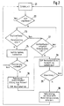
- Figure 2 shows a flowchart
- FIG. 1 shows a block diagram of a fuel delivery system in a schematic representation.
- the solid lines 6, 7 and 8 are said to Fuel lines and the dashed lines represent electrical connections.
- FIG. 1 is with a tank 3 via suction lines 8 two electrically operated fuel pumps 1,2 connected. On the output side, they convey via pressure lines 7 individual fuel injectors 5 the required fuel.
- a mixing valve 4 is preferably interposed, via that two pressure lines 7 are brought together. Not the electrical control of the is shown Injectors 5 by a corresponding control unit 9 can be controlled.
- the fuel pumps 1, 2 can identical or with different performances be trained.
- the fuel pumps are dashed over the Lines 11 shown by a control unit 9 both with Energy supplied as well as controlled and generated in the High pressure line 7 a predetermined pressure when in Are okay.
- the control unit 9 also contains one Evaluation stage 10, with which the pump function on their proper function is monitored. An error occurs this error is preferably visual to the driver and / or acoustically reported and in a corresponding Fault memory stored, which also for other functions can be provided.
- the control device 9 Inputs for sensors or signals based on the Evaluation of the pump function are necessary. For example is a pressure signal P, the lambda signal L and / or Flow rate Q can be entered via these inputs.
- the corresponding sensors are usually in the vehicle already exists, so that their signals from control unit 9 can also be used.
- the control unit 9 determines the fuel quantity to be delivered due to the operating parameters currently received z. B. P, L, Q by determining the line pressure in the High pressure line 7 and the specification of the injection duration for the injection valves 5. For example, at full load "Bold" pilot controlled, which with a lambda setpoint ⁇ 1 is set. However, it has been found that at pressure drop, d. H. if the delivery rate of the Fuel pumps is too low, the lambda setpoint ⁇ 1 at Full load cannot be set. In particular, could previously with a two-point control lambda at full load cannot be measured satisfactorily. Because with the two-point controller the internal combustion engine can become leaner can be recognized when lambda exceeds the threshold value, 1 ' exceeds.
- the basic consideration of the invention is a defective fuel pump 1.2 (EKP) both in Partial operation as well as at full load.
- EKP defective fuel pump 1.2
- Both fuel pumps are operated at partial load reciprocal operation with each other in their conveying capacity compared.
- Do the fuel pumps 1,2 the same Conveying capacity, this results in mutual operation no significant difference in the output.
- This is easiest to do when the fuel pumps checked at an operating point of the internal combustion engine be where the required flow rate from only one pump can be applied to meet fuel requirements Internal combustion engine in every case and error-free sure.
- the control output can be used for the comparison Lambda control are used and the two lambda Signals are compared.
- the Fuel pumps an at least approximately the same Conveyed capacity recognized, then it can also be concluded from it that errors of the lambda probe or the load detection are to be excluded.
- the fuel pumps at different lambda values with alternating operation of the Fuel pumps at the same engine operating point be excluded that it is an error detection as a result of other errors, for example with the lambda sensor itself or load detection related.
- the delivery rate of the individual fuel pumps 1,2 by determining the supply to the internal combustion engine Amount of fuel and that taken from the internal combustion engine To calculate fuel quantity. This procedure is especially for pumps with different delivery rates advantageous because here (except in the event of a total failure of one Fuel pump the comparison is not the same Operating point can be carried out. For example influences of the fuel system should also be taken into account become.
- the program also comes to this step if in Item 23 the fuel requirement was less than that Delivery rate of a fuel pump is. In this case the program jumps to position 27 and checks whether the Fuel requirement of the delivery rate of a fuel pump equivalent. If this is not the case, position 23 jumps back.
Landscapes
- Engineering & Computer Science (AREA)
- Chemical & Material Sciences (AREA)
- Combustion & Propulsion (AREA)
- Mechanical Engineering (AREA)
- General Engineering & Computer Science (AREA)
- Electrical Control Of Air Or Fuel Supplied To Internal-Combustion Engine (AREA)
- Fuel-Injection Apparatus (AREA)
Applications Claiming Priority (2)
| Application Number | Priority Date | Filing Date | Title |
|---|---|---|---|
| DE10030247A DE10030247A1 (de) | 2000-06-20 | 2000-06-20 | Verfahren zur Erkennung der Pumpenfunktion bei Fahrzeugen mit wenigstens zwei elektrischen Kraftstoffpumpen |
| DE10030247 | 2000-06-20 |
Publications (3)
| Publication Number | Publication Date |
|---|---|
| EP1167731A2 true EP1167731A2 (fr) | 2002-01-02 |
| EP1167731A3 EP1167731A3 (fr) | 2002-10-30 |
| EP1167731B1 EP1167731B1 (fr) | 2004-12-08 |
Family
ID=7646309
Family Applications (1)
| Application Number | Title | Priority Date | Filing Date |
|---|---|---|---|
| EP01110524A Expired - Lifetime EP1167731B1 (fr) | 2000-06-20 | 2001-04-28 | Méthode pour surveiller le fonctionnement de pompes pour véhicules ayant au moins deux pompes électriques à carburant |
Country Status (2)
| Country | Link |
|---|---|
| EP (1) | EP1167731B1 (fr) |
| DE (2) | DE10030247A1 (fr) |
Cited By (2)
| Publication number | Priority date | Publication date | Assignee | Title |
|---|---|---|---|---|
| EP2085603A1 (fr) | 2008-01-31 | 2009-08-05 | Caterpillar Motoren GmbH & Co. KG | Système et procédé pour éviter la surchauffe de pompe CR |
| WO2016173986A1 (fr) * | 2015-04-27 | 2016-11-03 | Continental Automotive Gmbh | Procédé de régulation d'un système d'alimentation en carburant |
Families Citing this family (2)
| Publication number | Priority date | Publication date | Assignee | Title |
|---|---|---|---|---|
| DE10319397B4 (de) * | 2003-04-30 | 2006-06-29 | Dr.Ing.H.C. F. Porsche Ag | Verfahren zur Überwachung eines Kraftstoffsystems für Brennkraftmaschinen mit mehreren Kraftstofffördereinheiten |
| CN113503216A (zh) * | 2021-08-25 | 2021-10-15 | 一汽解放汽车有限公司 | 一种柴油机燃油供给系统及其测试方法 |
Family Cites Families (5)
| Publication number | Priority date | Publication date | Assignee | Title |
|---|---|---|---|---|
| DE3247915A1 (de) * | 1982-12-24 | 1984-07-12 | Robert Bosch Gmbh, 7000 Stuttgart | Kraftstoffoerderanlage fuer brennkraftmaschinen, insbesondere in kraftfahrzeugen |
| DE3520660A1 (de) * | 1985-06-08 | 1986-12-11 | Bosch Gmbh Robert | Verfahren und vorrichtung zum sicheren betrieb einer brennkraftmaschine |
| JPH0374564A (ja) * | 1989-08-11 | 1991-03-29 | Japan Electron Control Syst Co Ltd | 燃料ポンプ制御装置 |
| US5623907A (en) * | 1995-06-09 | 1997-04-29 | Walbro Corporation | Liquid propane fuel delivery system |
| DE10002112C2 (de) * | 2000-01-19 | 2002-04-11 | Bosch Gmbh Robert | Verfahren zur Diagnose eines Kraftstoffversorgungssystems für Brennkraftmaschinen |
-
2000
- 2000-06-20 DE DE10030247A patent/DE10030247A1/de not_active Withdrawn
-
2001
- 2001-04-28 EP EP01110524A patent/EP1167731B1/fr not_active Expired - Lifetime
- 2001-04-28 DE DE2001504742 patent/DE50104742D1/de not_active Expired - Lifetime
Cited By (4)
| Publication number | Priority date | Publication date | Assignee | Title |
|---|---|---|---|---|
| EP2085603A1 (fr) | 2008-01-31 | 2009-08-05 | Caterpillar Motoren GmbH & Co. KG | Système et procédé pour éviter la surchauffe de pompe CR |
| WO2016173986A1 (fr) * | 2015-04-27 | 2016-11-03 | Continental Automotive Gmbh | Procédé de régulation d'un système d'alimentation en carburant |
| KR20170137873A (ko) * | 2015-04-27 | 2017-12-13 | 콘티넨탈 오토모티브 게엠베하 | 연료 전달 시스템을 피드백 제어하는 방법 |
| US10247126B2 (en) | 2015-04-27 | 2019-04-02 | Continental Automotive Gmbh | Feedback control method for a fuel delivery system |
Also Published As
| Publication number | Publication date |
|---|---|
| EP1167731B1 (fr) | 2004-12-08 |
| DE50104742D1 (de) | 2005-01-13 |
| EP1167731A3 (fr) | 2002-10-30 |
| DE10030247A1 (de) | 2002-01-03 |
Similar Documents
| Publication | Publication Date | Title |
|---|---|---|
| DE19941329B4 (de) | Steueranordnung für eine Brennkraftmaschine mit einer Fehlfunktionserfassungsfunktion | |
| EP1745197B1 (fr) | Procede pour introduire une substance reactive dans un conduit de gaz d'echappement d'un moteur a combustion interne | |
| EP1157201B1 (fr) | Systeme pour faire fonctionner un moteur a combustion interne, notamment d'un vehicule automobile | |
| DE102012113108B4 (de) | Fahrzeug mit einem system und einem verfahren zum diagnostizieren von sekundärlufteinblas-vorrichtung | |
| DE69829140T2 (de) | Diagnosesystem für das Treibstoffversorgungssystem eines Verbrennungsmotors | |
| DE102010018445B4 (de) | Maschinensteuersystem und Verfahren zur Kraftstoffdrucksensorleistungs-Diagnose auf der Grundlage der Hydrodynamik der Einspritzung | |
| DE60117090T2 (de) | Verfahren zur Bestimmung von Leckagen in einem Einspritzungsystem mit Verteilerleitung in einem Verbrennungsmotor | |
| DE102004016418B4 (de) | Fehlerdiagnosevorrichtung für eine Zufuhrvorrichtung für Sekundärluft | |
| DE102015108515B4 (de) | Vorrichtung und Verfahren zum Steuern eines Sauerstoffsensors | |
| DE102004050989B4 (de) | Verfahren zum Betreiben einer Abgasbehandlungsvorrichtung einer Brennkraftmaschine und Vorrichtung zur Durchführung des Verfahrens | |
| DE60215069T2 (de) | Gerät zum Bestimmen von Fehlern eines Drucksensors | |
| EP3298260B1 (fr) | Système d'injection pour moteur à combustion interne et moteur à combustion interne équipé de ce système d'injection | |
| DE102004028515B3 (de) | Verfahren und Vorrichtung zum Überwachen einer Kraftstoffzuführeinrichtung einer Brennkraftmaschine | |
| DE19836845B4 (de) | Verfahren und Vorrichtung zur Steuerung einer Antriebseinheit eines Kraftfahrzeugs | |
| EP1711704B1 (fr) | Procede pour surveiller le bon fonctionnement d'un systeme d'injection de carburant | |
| DE19859913B4 (de) | Kraftstoffzufuhrvorrichtung für Brennkraftmaschinen | |
| DE4309854C2 (de) | Verfahren und Vorrichtung zur Steuerung der Sekundärluftzufuhr für eine Brennkraftmaschine | |
| DE102006007698B4 (de) | Verfahren zum Betreiben einer Brennkraftmaschine, Computerprogramm-Produkt, Computerprogramm und Steuer- und/oder Regeleinrichtung für eine Brennkraftmaschine | |
| EP1167731B1 (fr) | Méthode pour surveiller le fonctionnement de pompes pour véhicules ayant au moins deux pompes électriques à carburant | |
| DE102010018006B4 (de) | Diagnosesystem für Steuerungsschaltungen von Systemen mit Funkenzündung und Direkteinspritzung | |
| EP1180210B2 (fr) | Procede et dispositif pour commander un moteur a combustion interne equipe d'un systeme de retraitement des gaz d'echappement | |
| DE10138045B4 (de) | Vorrichtung und Verfahren zur CPU-Diagnose | |
| DE102007060634A1 (de) | Verfahren zum Betreiben einer Brennkraftmaschine | |
| DE112014001033B4 (de) | Überwachungseinheit und Verfahren zur Überwachung eines Kraftstoffsystems | |
| DE19641942B4 (de) | Verfahren und Vorrichtung zur Fehlererkennung bei einer Brennkraftmaschine |
Legal Events
| Date | Code | Title | Description |
|---|---|---|---|
| PUAI | Public reference made under article 153(3) epc to a published international application that has entered the european phase |
Free format text: ORIGINAL CODE: 0009012 |
|
| AK | Designated contracting states |
Kind code of ref document: A2 Designated state(s): AT BE CH CY DE DK ES FI FR GB GR IE IT LI LU MC NL PT SE TR |
|
| AX | Request for extension of the european patent |
Free format text: AL;LT;LV;MK;RO;SI |
|
| PUAL | Search report despatched |
Free format text: ORIGINAL CODE: 0009013 |
|
| AK | Designated contracting states |
Kind code of ref document: A3 Designated state(s): AT BE CH CY DE DK ES FI FR GB GR IE IT LI LU MC NL PT SE TR |
|
| AX | Request for extension of the european patent |
Free format text: AL;LT;LV;MK;RO;SI |
|
| RIC1 | Information provided on ipc code assigned before grant |
Free format text: 7F 02D 41/22 A, 7F 02M 37/18 B |
|
| 17P | Request for examination filed |
Effective date: 20030502 |
|
| AKX | Designation fees paid |
Designated state(s): DE FR IT SE |
|
| GRAP | Despatch of communication of intention to grant a patent |
Free format text: ORIGINAL CODE: EPIDOSNIGR1 |
|
| GRAS | Grant fee paid |
Free format text: ORIGINAL CODE: EPIDOSNIGR3 |
|
| GRAA | (expected) grant |
Free format text: ORIGINAL CODE: 0009210 |
|
| RIN1 | Information on inventor provided before grant (corrected) |
Inventor name: JOOS, KLAUS Inventor name: WEISS, RUEDIGER Inventor name: KROEPKE, KLAUS Inventor name: GRASS, GERD |
|
| AK | Designated contracting states |
Kind code of ref document: B1 Designated state(s): DE FR IT SE |
|
| REG | Reference to a national code |
Ref country code: IE Ref legal event code: FG4D Free format text: GERMAN |
|
| REF | Corresponds to: |
Ref document number: 50104742 Country of ref document: DE Date of ref document: 20050113 Kind code of ref document: P |
|
| REG | Reference to a national code |
Ref country code: SE Ref legal event code: TRGR |
|
| PLBE | No opposition filed within time limit |
Free format text: ORIGINAL CODE: 0009261 |
|
| STAA | Information on the status of an ep patent application or granted ep patent |
Free format text: STATUS: NO OPPOSITION FILED WITHIN TIME LIMIT |
|
| ET | Fr: translation filed | ||
| 26N | No opposition filed |
Effective date: 20050909 |
|
| PGFP | Annual fee paid to national office [announced via postgrant information from national office to epo] |
Ref country code: DE Payment date: 20130627 Year of fee payment: 13 Ref country code: SE Payment date: 20130423 Year of fee payment: 13 |
|
| PGFP | Annual fee paid to national office [announced via postgrant information from national office to epo] |
Ref country code: FR Payment date: 20130523 Year of fee payment: 13 Ref country code: IT Payment date: 20130427 Year of fee payment: 13 |
|
| REG | Reference to a national code |
Ref country code: DE Ref legal event code: R119 Ref document number: 50104742 Country of ref document: DE |
|
| REG | Reference to a national code |
Ref country code: SE Ref legal event code: EUG |
|
| REG | Reference to a national code |
Ref country code: FR Ref legal event code: ST Effective date: 20141231 |
|
| REG | Reference to a national code |
Ref country code: DE Ref legal event code: R119 Ref document number: 50104742 Country of ref document: DE Effective date: 20141101 |
|
| PG25 | Lapsed in a contracting state [announced via postgrant information from national office to epo] |
Ref country code: SE Free format text: LAPSE BECAUSE OF NON-PAYMENT OF DUE FEES Effective date: 20140429 Ref country code: DE Free format text: LAPSE BECAUSE OF NON-PAYMENT OF DUE FEES Effective date: 20141101 |
|
| PG25 | Lapsed in a contracting state [announced via postgrant information from national office to epo] |
Ref country code: FR Free format text: LAPSE BECAUSE OF NON-PAYMENT OF DUE FEES Effective date: 20140430 |
|
| PG25 | Lapsed in a contracting state [announced via postgrant information from national office to epo] |
Ref country code: IT Free format text: LAPSE BECAUSE OF NON-PAYMENT OF DUE FEES Effective date: 20140428 |