EP1167733B1 - Procédé pour le fonctionnement d'un moteur à combustion interne avec turbocompresseur - Google Patents
Procédé pour le fonctionnement d'un moteur à combustion interne avec turbocompresseur Download PDFInfo
- Publication number
- EP1167733B1 EP1167733B1 EP01114914A EP01114914A EP1167733B1 EP 1167733 B1 EP1167733 B1 EP 1167733B1 EP 01114914 A EP01114914 A EP 01114914A EP 01114914 A EP01114914 A EP 01114914A EP 1167733 B1 EP1167733 B1 EP 1167733B1
- Authority
- EP
- European Patent Office
- Prior art keywords
- injection
- exhaust gas
- special operation
- normal
- engine
- Prior art date
- Legal status (The legal status is an assumption and is not a legal conclusion. Google has not performed a legal analysis and makes no representation as to the accuracy of the status listed.)
- Expired - Lifetime
Links
- 238000000034 method Methods 0.000 title claims description 20
- 238000002347 injection Methods 0.000 claims description 81
- 239000007924 injection Substances 0.000 claims description 81
- 238000002485 combustion reaction Methods 0.000 claims description 49
- 239000000446 fuel Substances 0.000 claims description 27
- 239000000203 mixture Substances 0.000 claims description 15
- XLYOFNOQVPJJNP-UHFFFAOYSA-N water Substances O XLYOFNOQVPJJNP-UHFFFAOYSA-N 0.000 claims description 4
- 238000001816 cooling Methods 0.000 claims description 2
- 230000006698 induction Effects 0.000 claims 2
- 230000001960 triggered effect Effects 0.000 claims 2
- 238000010344 co-firing Methods 0.000 description 4
- 230000001419 dependent effect Effects 0.000 description 4
- 230000001133 acceleration Effects 0.000 description 3
- 230000004044 response Effects 0.000 description 3
- 230000007704 transition Effects 0.000 description 3
- 230000008859 change Effects 0.000 description 2
- 230000018109 developmental process Effects 0.000 description 2
- 230000008569 process Effects 0.000 description 2
- 230000008929 regeneration Effects 0.000 description 2
- 238000011069 regeneration method Methods 0.000 description 2
- 239000000779 smoke Substances 0.000 description 2
- 238000011144 upstream manufacturing Methods 0.000 description 2
- 230000006978 adaptation Effects 0.000 description 1
- 230000005540 biological transmission Effects 0.000 description 1
- 238000006243 chemical reaction Methods 0.000 description 1
- 238000010276 construction Methods 0.000 description 1
- 230000003247 decreasing effect Effects 0.000 description 1
- XDDAORKBJWWYJS-UHFFFAOYSA-N glyphosate Chemical group OC(=O)CNCP(O)(O)=O XDDAORKBJWWYJS-UHFFFAOYSA-N 0.000 description 1
- 230000001771 impaired effect Effects 0.000 description 1
- 230000006872 improvement Effects 0.000 description 1
- 238000011017 operating method Methods 0.000 description 1
- 230000001105 regulatory effect Effects 0.000 description 1
- 230000001052 transient effect Effects 0.000 description 1
Images

Classifications
-
- F—MECHANICAL ENGINEERING; LIGHTING; HEATING; WEAPONS; BLASTING
- F02—COMBUSTION ENGINES; HOT-GAS OR COMBUSTION-PRODUCT ENGINE PLANTS
- F02D—CONTROLLING COMBUSTION ENGINES
- F02D23/00—Controlling engines characterised by their being supercharged
- F02D23/02—Controlling engines characterised by their being supercharged the engines being of fuel-injection type
-
- F—MECHANICAL ENGINEERING; LIGHTING; HEATING; WEAPONS; BLASTING
- F02—COMBUSTION ENGINES; HOT-GAS OR COMBUSTION-PRODUCT ENGINE PLANTS
- F02D—CONTROLLING COMBUSTION ENGINES
- F02D41/00—Electrical control of supply of combustible mixture or its constituents
- F02D41/0002—Controlling intake air
- F02D41/0007—Controlling intake air for control of turbo-charged or super-charged engines
-
- F—MECHANICAL ENGINEERING; LIGHTING; HEATING; WEAPONS; BLASTING
- F02—COMBUSTION ENGINES; HOT-GAS OR COMBUSTION-PRODUCT ENGINE PLANTS
- F02D—CONTROLLING COMBUSTION ENGINES
- F02D41/00—Electrical control of supply of combustible mixture or its constituents
- F02D41/30—Controlling fuel injection
- F02D41/38—Controlling fuel injection of the high pressure type
- F02D41/40—Controlling fuel injection of the high pressure type with means for controlling injection timing or duration
- F02D41/402—Multiple injections
- F02D41/405—Multiple injections with post injections
-
- F—MECHANICAL ENGINEERING; LIGHTING; HEATING; WEAPONS; BLASTING
- F02—COMBUSTION ENGINES; HOT-GAS OR COMBUSTION-PRODUCT ENGINE PLANTS
- F02B—INTERNAL-COMBUSTION PISTON ENGINES; COMBUSTION ENGINES IN GENERAL
- F02B29/00—Engines characterised by provision for charging or scavenging not provided for in groups F02B25/00, F02B27/00 or F02B33/00 - F02B39/00; Details thereof
- F02B29/04—Cooling of air intake supply
- F02B29/0406—Layout of the intake air cooling or coolant circuit
-
- F—MECHANICAL ENGINEERING; LIGHTING; HEATING; WEAPONS; BLASTING
- F02—COMBUSTION ENGINES; HOT-GAS OR COMBUSTION-PRODUCT ENGINE PLANTS
- F02B—INTERNAL-COMBUSTION PISTON ENGINES; COMBUSTION ENGINES IN GENERAL
- F02B37/00—Engines characterised by provision of pumps driven at least for part of the time by exhaust
-
- F—MECHANICAL ENGINEERING; LIGHTING; HEATING; WEAPONS; BLASTING
- F02—COMBUSTION ENGINES; HOT-GAS OR COMBUSTION-PRODUCT ENGINE PLANTS
- F02M—SUPPLYING COMBUSTION ENGINES IN GENERAL WITH COMBUSTIBLE MIXTURES OR CONSTITUENTS THEREOF
- F02M26/00—Engine-pertinent apparatus for adding exhaust gases to combustion-air, main fuel or fuel-air mixture, e.g. by exhaust gas recirculation [EGR] systems
- F02M26/02—EGR systems specially adapted for supercharged engines
- F02M26/04—EGR systems specially adapted for supercharged engines with a single turbocharger
- F02M26/05—High pressure loops, i.e. wherein recirculated exhaust gas is taken out from the exhaust system upstream of the turbine and reintroduced into the intake system downstream of the compressor
-
- F—MECHANICAL ENGINEERING; LIGHTING; HEATING; WEAPONS; BLASTING
- F02—COMBUSTION ENGINES; HOT-GAS OR COMBUSTION-PRODUCT ENGINE PLANTS
- F02M—SUPPLYING COMBUSTION ENGINES IN GENERAL WITH COMBUSTIBLE MIXTURES OR CONSTITUENTS THEREOF
- F02M26/00—Engine-pertinent apparatus for adding exhaust gases to combustion-air, main fuel or fuel-air mixture, e.g. by exhaust gas recirculation [EGR] systems
- F02M26/02—EGR systems specially adapted for supercharged engines
- F02M26/09—Constructional details, e.g. structural combinations of EGR systems and supercharger systems; Arrangement of the EGR and supercharger systems with respect to the engine
- F02M26/10—Constructional details, e.g. structural combinations of EGR systems and supercharger systems; Arrangement of the EGR and supercharger systems with respect to the engine having means to increase the pressure difference between the exhaust and intake system, e.g. venturis, variable geometry turbines, check valves using pressure pulsations or throttles in the air intake or exhaust system
-
- F—MECHANICAL ENGINEERING; LIGHTING; HEATING; WEAPONS; BLASTING
- F02—COMBUSTION ENGINES; HOT-GAS OR COMBUSTION-PRODUCT ENGINE PLANTS
- F02M—SUPPLYING COMBUSTION ENGINES IN GENERAL WITH COMBUSTIBLE MIXTURES OR CONSTITUENTS THEREOF
- F02M26/00—Engine-pertinent apparatus for adding exhaust gases to combustion-air, main fuel or fuel-air mixture, e.g. by exhaust gas recirculation [EGR] systems
- F02M26/13—Arrangement or layout of EGR passages, e.g. in relation to specific engine parts or for incorporation of accessories
- F02M26/17—Arrangement or layout of EGR passages, e.g. in relation to specific engine parts or for incorporation of accessories in relation to the intake system
- F02M26/21—Arrangement or layout of EGR passages, e.g. in relation to specific engine parts or for incorporation of accessories in relation to the intake system with EGR valves located at or near the connection to the intake system
-
- F—MECHANICAL ENGINEERING; LIGHTING; HEATING; WEAPONS; BLASTING
- F02—COMBUSTION ENGINES; HOT-GAS OR COMBUSTION-PRODUCT ENGINE PLANTS
- F02M—SUPPLYING COMBUSTION ENGINES IN GENERAL WITH COMBUSTIBLE MIXTURES OR CONSTITUENTS THEREOF
- F02M26/00—Engine-pertinent apparatus for adding exhaust gases to combustion-air, main fuel or fuel-air mixture, e.g. by exhaust gas recirculation [EGR] systems
- F02M26/13—Arrangement or layout of EGR passages, e.g. in relation to specific engine parts or for incorporation of accessories
- F02M26/22—Arrangement or layout of EGR passages, e.g. in relation to specific engine parts or for incorporation of accessories with coolers in the recirculation passage
- F02M26/23—Layout, e.g. schematics
- F02M26/28—Layout, e.g. schematics with liquid-cooled heat exchangers
-
- Y—GENERAL TAGGING OF NEW TECHNOLOGICAL DEVELOPMENTS; GENERAL TAGGING OF CROSS-SECTIONAL TECHNOLOGIES SPANNING OVER SEVERAL SECTIONS OF THE IPC; TECHNICAL SUBJECTS COVERED BY FORMER USPC CROSS-REFERENCE ART COLLECTIONS [XRACs] AND DIGESTS
- Y02—TECHNOLOGIES OR APPLICATIONS FOR MITIGATION OR ADAPTATION AGAINST CLIMATE CHANGE
- Y02T—CLIMATE CHANGE MITIGATION TECHNOLOGIES RELATED TO TRANSPORTATION
- Y02T10/00—Road transport of goods or passengers
- Y02T10/10—Internal combustion engine [ICE] based vehicles
- Y02T10/12—Improving ICE efficiencies
-
- Y—GENERAL TAGGING OF NEW TECHNOLOGICAL DEVELOPMENTS; GENERAL TAGGING OF CROSS-SECTIONAL TECHNOLOGIES SPANNING OVER SEVERAL SECTIONS OF THE IPC; TECHNICAL SUBJECTS COVERED BY FORMER USPC CROSS-REFERENCE ART COLLECTIONS [XRACs] AND DIGESTS
- Y02—TECHNOLOGIES OR APPLICATIONS FOR MITIGATION OR ADAPTATION AGAINST CLIMATE CHANGE
- Y02T—CLIMATE CHANGE MITIGATION TECHNOLOGIES RELATED TO TRANSPORTATION
- Y02T10/00—Road transport of goods or passengers
- Y02T10/10—Internal combustion engine [ICE] based vehicles
- Y02T10/40—Engine management systems
Definitions
- the invention relates to a method for operating an internal combustion engine with exhaust gas turbocharger, where between one Normal operation and a special mode can be switched and in special operation at least one main fuel injection and at least one post fuel injection provided are.
- German patent DE 197 50 226 C1 is a method known for operating an internal combustion engine, in which a change between a lean operation and a rich operation a diesel engine is enabled. Depending on predetermined Switching criteria is set to lean operation or rich operation the diesel engine switched. For lean operation and for rich operation are separate maps for operation stored the diesel engine.
- German patent application DE 199 51 096 A1 discloses a method for operating an internal combustion engine known with turbocharger, in which between a Normal operation and a special operation can be switched where the special operation is used to add a turbo lag to reduce a diesel engine with turbocharger. For this is switched to the special mode with a positive load step, in which the exhaust gas temperature and / or the exhaust gas pressure upstream of the exhaust gas turbocharger relative to normal operation are increased.
- a main fuel injection and a post fuel injection may be provided where a substantially complete Combustion of the fuel of the post-injection quantity can take place.
- the diesel engine will then, stoichiometric when fitted with an emission control system or superstoichiometric, i. lean, operated.
- Modern emission control systems require a conversion of the exhaust gas composition from rich to lean.
- rich combustion is from time to time required to regenerate, for example, NO x -Adsorbersysteme.
- an accelerated charge pressure buildup is at an internal combustion engine with turbocharger at the same time optional adjustment of a rich or lean exhaust gas composition be enabled.
- this is a method according to the preamble of claim 1, wherein in response to a positive Load jump between normal operation and that to increase the exhaust enthalpy provided special operation switched is, with the post fuel injection in the special mode so is adjusted so that it burns essentially in the combustion chamber and an increase in exhaust enthalpy and a setting causing a rich or lean exhaust gas composition.
- the post-injection burned in the combustion chamber contributes to the engine load at and leads to increase the exhaust enthalpy. simultaneously can by means of the post fuel injection a setting the exhaust gas composition between rich and lean done.
- the amount and time of the post fuel injection are important adjustment parameters for engine load, increase exhaust enthalpy and adjusting the exhaust gas composition.
- Turbochargers use the exhaust enthalpy to get on the fresh air side to drive a compressor. After a positive load jump the turbocharger has to be accelerated.
- the necessary Exhaust enthalpy may occur during conventional operating procedures not be made available immediately as they pass through the smoke limitation is limited.
- the inventive method produces a higher exhaust gas enthalpy with the same smoke number and thereby speed up the boost pressure buildup, i. it shortens the turbo lag.
- the problem underlying the invention is also by a Method according to the preamble of claim 2, wherein in response to a positive load jump between normal operation and provided for increasing the exhaust enthalpy Special mode is switched, the post fuel injection in special operation is set so that they are substantially burned in the combustion chamber and an increase in exhaust enthalpy caused and that in special operation at least one provided further remote post-injection of the fuel is, by means of essentially a setting of a fat or lean exhaust gas composition.
- an injection start of the Main injection in normal and special operation essentially is equal to.
- the internal combustion engine with the inventive method is operated, is a switch between normal and special operation not noticeable or audible.
- a changeover time between normal operation and special operation and one Main injection quantity during the switching time depending on an engine torque, a derivative of the engine torque, an engine speed, a derivative of the engine speed, a driving speed, an engaged driving gear, a total injection quantity, an air mass in the intake, a derivative of Air mass, a water temperature in the cooling system, an outside air temperature, a suction pipe temperature, an exhaust gas temperature, an ambient pressure, an intake manifold pressure and / or a Exhaust pressure can be adjusted.
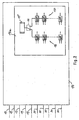
- the diesel engine 1 shown in FIG. 1 can optionally in substoichiometric operation, i. Combustion air ratio ⁇ ⁇ 1 or rich combustion, or in stoichiometric or superstoichiometric Operation, i. Combustion air ratio ⁇ ⁇ 1 or lean combustion.
- an exhaust gas recirculation device Between an exhaust pipe 30 and an intake air pipe 32nd an exhaust gas recirculation device is arranged, which is an actuator 2 has.
- the actuator 2 may by a power-operated Actuator 3 in response to signals of an electronic Motor control are operated.
- an exhaust gas recirculation cooler 4 In the exhaust gas recirculation line an exhaust gas recirculation cooler 4 is provided.
- the diesel engine is equipped with a supercharger, an exhaust gas turbocharger 5, equipped.
- the exhaust gas turbocharger 5 has a Actuator 6, with an exhaust back pressure, which flowed through Cross section and / or the flowing exhaust gas volume adjusted can be.
- the actuator 6 with a servo-operated actuator 7 provided as an electric actuator can be trained.
- the power-operated actuator is dependent on signals of the electronic engine control actuated.
- the entering at a and through the turbocharger 5 compressed fresh air is through a charge air cooler 35 led. From the exhaust gas turbocharger 5 occurs exhaust gas in the direction of the arrow b in an emission control system.
- Throttling device 8 arranged in the intake air line, which can be actuated by means of an actuator 9.
- the Actuator 9 is associated with a power-operated actuator 10, which also depends on signals from the electronic Motor control can be operated.
- the diesel engine 1 is provided with a system for reducing the inlet cross section provided, in the present case as each one Throttle valve 11 in the intake manifold 32 of each cylinder is trained.
- the throttle valve 11 is a common Assigned actuator 12, which by means of a power-operated Actuator 13 can be operated. In dependence of Signals of the electronic engine control 14 are the throttle 11 actuated.
- the engine control 14 can also by a Normal mode can be switched to a special mode to To generate a high exhaust gas enthalpy and a high exhaust gas temperature.
- switching to special operation is at a positive load step avoided the so-called turbo lag.
- a rich combustion can by means of the engine control 14 thereby be achieved that changes a course of injection will, allowing early combustion of the injected fuel amount is reached, and that a co-firing post-injection is provided in the combustion chamber, in terms of quantity and time is adapted to the engine operation.
- the diesel engine is one in quantity and time regardless of engine operation metered fuel injection 33 provided in the exhaust system.
- Sensors 34 provide signals, for example Pressure and temperature, to the engine control 14.
- a transition from a lean burn to a fat burn takes place by a continuously or discontinuously decreasing Amount of at least one main injection and a adjusted amount of co-firing post-injection, that the indexed moment remains constant.
- a transition from a rich to a lean burn by a continuously or discontinuously increasing Amount of at least one main injection and one adapted amount of co-firing post-injection, that the indexed moment remains constant.
- the engine controller 14 In the engine control by the engine controller 14 are the two Motor modes, normal operation and special operation, displayed. It is in the one engine mode, the Normal operation, the application for the conventional, normal Combustion layer deposited, and in the map structure for the second engine operating mode, the special operation, becomes an application pictured with multiple injections, both a superstoichiometric as well as a substoichiometric Motor operation enabled.
- Motor controller 14 includes a unit 14a as shown in FIG. by means of between lean engine operation and rich engine operation can be switched.
- the unit 14a are maps 17 for rich engine operation and maps 18 for lean Motor operation saved.
- switching criteria checked and then by means of a switch 16 then either set a rich or lean engine operation.
- the engine controller 14 receives sensor signals, which serve to check the switching criteria in block 15.
- the sensor signals on lines 19 are from the engine controller 14 also used to determine if a positive Load jump is present and in the special mode to increase the exhaust gas enthalpy must be switched.
- the motor controller 14 outputs corresponding signals to a Injection system 21 and further, shown in FIG. 1 actuators.
- a changeover between normal and special operation takes place according to of the invention based on criteria, which in the published patent application DE 199 51 096 A1 are cited.
- switching criteria where the engine control system a momentary switching from normal operation to special operation, For example, if a specific accelerator pedal position is suggested, preferably from a so-called "kick-down position" differs in vehicles with automatic transmission is known.
- switching criteria can also others Signals of a motor control are evaluated, which with a Driver's request correlate to acceleration. For example These can be signals for changing the accelerator pedal position and / or for changing the combustion supplied Fuel quantity within a certain time and / or signals for the difference between one desired by the driver Fuel quantity and one of the engine control released Be fuel quantity.
- the switching criteria to switch to the special mode chosen so that the driver e.g. by a slight accelerator pedal pressure a normal acceleration in normal operation and by a correspondingly stronger Accelerator pedal a strong acceleration with switching in can generate the special operation.
- the switch back to the Normal operation takes place for example by a timer, which after a predetermined period of time, e.g. after a second, switching to normal operation triggers.
- the switch back to normal operation made dependent be, that a predetermined, in particular according to the field stored Target boost pressure is achieved.
- the proposed method according to the invention can be characterized characterize that the total amount of fuel through any number of pre-injections, one to two main injections, a co-firing post-injection and if necessary another, stepped post injection into the Combustion chamber is introduced.
- the injection starts of the pilot injections correspond to the inventive method in essentially at the start of injection of the pilot injections normal diesel engine combustion.
- the injection starts the main injection correspond to the invention Procedure essentially injection start of the main injections in normal diesel engine combustion.
- the injection start of the first post-injection is designed so that combustion of this post-injection quantity in the combustion chamber takes place, so that the first post-injection on the one hand to Contributed engine load and on the other hand, a very high Exhaust gas temperature causes.
- the maximum pressure increase in the combustion chamber and the position of the maximum Pressure increase in the combustion chamber correspond to this combustion process in about the values of the normal diesel engine Combustion with pre-injection and main injection.
- the regulation of Engine load takes place via the injection quantity participating in the combustion.
- the exhaust gas turbocharger 5 in the diesel engine by means of the engine control a regulation of the intake manifold pressure provided, the by means of the throttle valve 11, the exhaust gas turbocharger 5 and optionally by means of the exhaust gas recirculation valve 2 and the exhaust gas turbocharger 5 takes place. Furthermore, an air mass control means an air mass meter and the exhaust gas recirculation valve 2, optionally provided by means of the throttle valves 8 and 11 his.
- the air ratio is determined by means of the exhaust gas recirculation valve 2 and by means of the combustion in the combustion chamber substantially Post-injection and optionally by means of further, remote Post-injection regulated.
- an accelerated Boost pressure buildup in an internal combustion engine with Exhaust gas turbocharger is achieved by passing through a substantially in the combustion chamber burning post injection an increase in Exhaust enthalpy is effected. Since this first post injection in the essentially burned in the combustion chamber, it also contributes to the engine load at. By increasing the exhaust gas enthalpy, the exhaust gas turbine the exhaust gas turbocharger faster brought to speed be built so that a boost pressure in the intake faster becomes. As a result, the so-called turbo lag in positive Load jump avoided.
- the invention by means of the combustion in the combustion chamber substantially After injection also a setting of a fat or lean exhaust gas composition take place.
- This will be regeneration phases an emission control system that uses a rich exhaust gas composition require, despite balancing the turbocharger not interrupted or impaired.
- remote post-injection can essentially an adjustment of a rich or lean exhaust gas composition respectively.
- the setting of a rich or lean exhaust gas composition takes place according to the second embodiment Accordingly, essentially exclusively by means of the other remote Injection. This can be time and amount the first, substantially in the combustion chamber burning post-injection, on the for the present engine operating condition optimal values remain.
Landscapes
- Engineering & Computer Science (AREA)
- Chemical & Material Sciences (AREA)
- Combustion & Propulsion (AREA)
- Mechanical Engineering (AREA)
- General Engineering & Computer Science (AREA)
- Output Control And Ontrol Of Special Type Engine (AREA)
- Electrical Control Of Air Or Fuel Supplied To Internal-Combustion Engine (AREA)
- Supercharger (AREA)
- Exhaust Gas After Treatment (AREA)
- Exhaust-Gas Circulating Devices (AREA)
Claims (5)
- Procédé pour le fonctionnement d'un moteur à combustion interne avec turbocompresseur, dans lequel on peut effectuer une commutation entre un fonctionnement normal et un fonctionnement spécial et dans lequel, en fonctionnement spécial, au moins une injection principale de carburant et au moins une post-injection de carburant sont prévues, caractérisé en ce que, en réaction à une variation brusque de charge positive, on effectue une commutation entre le fonctionnement normal et le fonctionnement spécial prévu pour l'augmentation de l'enthalpie des gaz d'échappement, moyennant quoi la post-injection de carburant en fonctionnement spécial est réglée de telle manière qu'elle brûle essentiellement dans la chambre d'explosion et qu'elle provoque une augmentation de l'enthalpie des gaz d'échappement ainsi que le réglage d'une composition des gaz d'échappement riche ou pauvre.
- Procédé pour le fonctionnement d'un moteur diesel avec turbocompresseur, dans lequel on peut effectuer une commutation entre un fonctionnement normal et un fonctionnement spécial et dans lequel, en fonctionnement spécial, au moins une injection principale de carburant et au moins une post-injection de carburant sont prévues, caractérisé en ce que, en réaction à une variation brusque de charge positive, on effectue une commutation entre le fonctionnement normal et le fonctionnement spécial prévu pour l'augmentation de l'enthalpie des gaz d'échappement, moyennant quoi la post-injection de carburant en fonctionnement spécial est réglée de telle manière qu'elle brûle essentiellement dans la chambre d'explosion et qu'elle provoque une augmentation de l'enthalpie des gaz d'échappement et en ce que, en fonctionnement spécial, il est prévu au moins une autre post-injection de carburant décalée grâce à laquelle on effectue le réglage d'une composition des gaz d'échappement riche ou pauvre.
- Procédé selon la revendication 1 ou 2, caractérisé en ce que, en fonctionnement normal et en fonctionnement spécial, il est prévu une pré-injection de carburant en fonction du régime du moteur à combustion interne, dont le début d'injection est sensiblement le même en fonctionnement normal et en fonctionnement spécial.
- Procédé selon l'une quelconque des revendications précédentes, caractérisé en ce qu'un début d'injection de l'injection principale est sensiblement le même en fonctionnement normal et en fonctionnement spécial.
- Procédé selon l'une quelconque des revendications précédentes, caractérisé en ce que l'on règle un temps de commutation entre le fonctionnement normal et le fonctionnement spécial et une quantité d'injection principale pendant le temps de commutation en fonction d'un couple moteur, d'une dérivée du couple moteur, d'une vitesse du moteur, d'une dérivée de la vitesse du moteur, d'une vitesse de marche, d'une vitesse enclenchée, d'une quantité totale d'injection, d'une masse d'air sur le trajet d'admission, d'une dérivée de la masse d'air, d'une température de l'eau dans le circuit de refroidissement, d'une température de l'air extérieur, d'une température du collecteur d'admission, d'une température des gaz d'échappement, d'une pression ambiante, d'une pression du collecteur d'admission et/ou d'une pression des gaz d'échappement.
Applications Claiming Priority (2)
| Application Number | Priority Date | Filing Date | Title |
|---|---|---|---|
| DE10029502 | 2000-06-21 | ||
| DE10029502A DE10029502A1 (de) | 2000-06-21 | 2000-06-21 | Beschleunigter Aufbau des Ladedrucks durch ein mehrstufiges Brennverfahren für Dieselmotoren |
Publications (4)
| Publication Number | Publication Date |
|---|---|
| EP1167733A2 EP1167733A2 (fr) | 2002-01-02 |
| EP1167733A3 EP1167733A3 (fr) | 2004-01-02 |
| EP1167733B1 true EP1167733B1 (fr) | 2004-12-01 |
| EP1167733B2 EP1167733B2 (fr) | 2013-11-20 |
Family
ID=7645830
Family Applications (1)
| Application Number | Title | Priority Date | Filing Date |
|---|---|---|---|
| EP01114914.3A Expired - Lifetime EP1167733B2 (fr) | 2000-06-21 | 2001-06-20 | Procédé pour le fonctionnement d'un moteur à combustion interne avec turbocompresseur |
Country Status (3)
| Country | Link |
|---|---|
| US (1) | US6619033B2 (fr) |
| EP (1) | EP1167733B2 (fr) |
| DE (2) | DE10029502A1 (fr) |
Families Citing this family (22)
| Publication number | Priority date | Publication date | Assignee | Title |
|---|---|---|---|---|
| DE10029502A1 (de) † | 2000-06-21 | 2002-01-31 | Daimler Chrysler Ag | Beschleunigter Aufbau des Ladedrucks durch ein mehrstufiges Brennverfahren für Dieselmotoren |
| DE10201016A1 (de) * | 2002-01-11 | 2003-07-24 | Daimler Chrysler Ag | Verfahren zum Betrieb einer Brennkraftmaschine mit Abgasreinigungsanlage und Brennkraftmaschine |
| FR2840649B1 (fr) * | 2002-06-06 | 2005-05-20 | Renault Sa | Procede d'augmentation de performances d'un moteur suralimente |
| US6863058B2 (en) * | 2003-02-03 | 2005-03-08 | Ford Global Technologies, Llc | System and method for reducing NOx emissions during transient conditions in a diesel fueled vehicle |
| US7079938B2 (en) * | 2003-07-25 | 2006-07-18 | Detroit Diesel Corporation | Influence of engine parameters on condensation protection strategies |
| US6934621B2 (en) * | 2003-07-25 | 2005-08-23 | Detroit Diesel Corporation | Re-entry strategy from boost mode to EGR mode |
| US6931837B2 (en) * | 2003-11-06 | 2005-08-23 | International Engine Intellectual Property Company, Llc | Control strategy for lean-to-rich transitions in an internal combustion engine |
| US6948482B2 (en) | 2003-12-09 | 2005-09-27 | Caterpillar Inc. | Engine cylinder temperature control |
| FR2864161B1 (fr) * | 2003-12-18 | 2007-08-10 | Inst Francais Du Petrole | Procede de controle d'un moteur a combustion interne suralimente |
| DE102004025406B4 (de) * | 2004-05-24 | 2015-11-12 | Volkswagen Ag | Verfahren zur Einspritzsteuerung eines Verbrennungsmotors und entsprechend ausgestaltete Motorsteuerung |
| US6990951B1 (en) * | 2004-07-12 | 2006-01-31 | International Engine Intellectual Property Company, Llc | Torque control strategy for a diesel engine during lean-rich modulation using independent fuel injection maps |
| JP2006207417A (ja) * | 2005-01-26 | 2006-08-10 | Denso Corp | 過給機付エンジン制御システム |
| DE102005005559B4 (de) * | 2005-02-07 | 2018-11-15 | Volkswagen Ag | Verfahren zum Betreiben einer Brennkraftmaschine mit Abgasturbolader |
| US8126632B2 (en) | 2007-10-26 | 2012-02-28 | Ford Global Technologies, Llc | Engine idle speed and turbocharger speed control |
| US8131446B2 (en) | 2007-10-29 | 2012-03-06 | Ford Global Technologies, Llc | Engine idle speed and turbocharger speed control |
| US8474258B2 (en) * | 2008-09-24 | 2013-07-02 | Deere & Company | Stoichiometric compression ignition engine with increased power output |
| JP5370243B2 (ja) * | 2010-03-31 | 2013-12-18 | マツダ株式会社 | ターボ過給機付きディーゼルエンジンの制御装置 |
| US8886440B2 (en) * | 2010-04-16 | 2014-11-11 | GM Global Technology Operations LLC | Method and system for reducing turbo lag in an engine |
| WO2015067845A1 (fr) * | 2013-11-07 | 2015-05-14 | Wärtsilä Finland Oy | Moteur à combustion ayant deux turbocompresseurs reliés en série et procédé pour le fonctionnement de ce moteur |
| DE102017200837A1 (de) | 2017-01-19 | 2018-07-19 | Robert Bosch Gmbh | Verfahren und Vorrichtung zum Betreiben eines aufgeladenen kraftstoffgeführten Verbrennungsmotors |
| US11248546B1 (en) * | 2020-10-26 | 2022-02-15 | Tula Technology, Inc. | Fast torque response for boosted engines |
| US11635035B2 (en) * | 2020-10-26 | 2023-04-25 | Tula Technology, Inc. | Fast torque response for boosted engines |
Family Cites Families (32)
| Publication number | Priority date | Publication date | Assignee | Title |
|---|---|---|---|---|
| US4233815A (en) * | 1970-05-05 | 1980-11-18 | Etat Francais | Methods of supercharging a diesel engine, in supercharged diesel engines, and in supercharging units for diesel engines |
| GB1602869A (en) * | 1977-11-25 | 1981-11-18 | Garrett Corp | Turbocharged internal combustion engines |
| US4424676A (en) * | 1979-09-12 | 1984-01-10 | M & W Gear Company | Supplementary fuel injection system for a turbocharged internal combustion engine |
| JPS5681235A (en) * | 1979-12-04 | 1981-07-03 | Nippon Soken Inc | Air-fuel ratio controller for internal combustion engine with supercharger |
| JPS60261941A (ja) * | 1984-06-08 | 1985-12-25 | Mazda Motor Corp | 過給機付エンジン |
| JPS6196138A (ja) * | 1984-10-16 | 1986-05-14 | Ngk Spark Plug Co Ltd | 過給機付内燃機関 |
| FR2605055B1 (fr) * | 1986-10-08 | 1991-09-27 | Daimler Benz Ag | Procede d'injection directe de carburant pour un moteur diesel |
| JP2579936B2 (ja) * | 1987-04-02 | 1997-02-12 | マツダ株式会社 | 過給機付エンジンの空燃比制御装置 |
| JPH0833117B2 (ja) * | 1988-07-07 | 1996-03-29 | 三菱自動車工業株式会社 | 燃料噴射装置 |
| US4953515A (en) * | 1988-11-28 | 1990-09-04 | Fehr William A | Diesel engine secondary fuel injection system |
| US5255655A (en) * | 1989-06-15 | 1993-10-26 | Robert Bosch Gmbh | Fuel injection system for an internal combustion engine |
| JP2677423B2 (ja) * | 1989-07-24 | 1997-11-17 | 富士通テン株式会社 | 内燃機関の燃料噴射量制御方法 |
| US5381659A (en) * | 1993-04-06 | 1995-01-17 | Hughes Aircraft Company | Engine exhaust reburner system and method |
| EP0621400B1 (fr) * | 1993-04-23 | 1999-03-31 | Daimler-Benz Aktiengesellschaft | Moteur à combustion interne à injection et à compression d'air avec un dispositif pout traiter les gaz d'échappement à fin de réduire les oxides azoté |
| IT1266890B1 (it) * | 1994-07-22 | 1997-01-21 | Fiat Ricerche | Metodo di attivazione di un catalizzatore "denox" in un motore diesel con un sistema di iniezione a collettore comune. |
| DE4439573A1 (de) † | 1994-11-05 | 1996-05-09 | Mtu Friedrichshafen Gmbh | Verfahren zum Betrieb einer Brennkraftmaschine mit einem Abgasturbolader |
| EP0793776B1 (fr) * | 1995-09-22 | 2001-12-05 | Robert Bosch Gmbh | Procede et dispositif de commande d'un moteur a combustion interne |
| US5839275A (en) * | 1996-08-20 | 1998-11-24 | Toyota Jidosha Kabushiki Kaisha | Fuel injection control device for a direct injection type engine |
| DE19639172C2 (de) † | 1996-09-24 | 2001-11-08 | Siemens Ag | Kraftstoff-Direkteinspritzverfahren für eine Dieselbrennkraftmaschine |
| JP4010046B2 (ja) * | 1997-06-24 | 2007-11-21 | トヨタ自動車株式会社 | 圧縮着火式内燃機関 |
| DE19747231A1 (de) * | 1997-10-25 | 1999-04-29 | Bosch Gmbh Robert | Verfahren zur Einspritzung von Kraftstoff in die Brennräume einer luftverdichtenden, selbstzündenden Brennkraftmaschine |
| DE19750226C1 (de) * | 1997-11-13 | 1998-10-29 | Daimler Benz Ag | Motorregelsystem für einen Dieselmotor |
| DE19803807A1 (de) † | 1998-01-31 | 1999-08-05 | Volkswagen Ag | Brennkraftmaschine und Verfahren zum Betreiben einer aufgeladenen Brennkraftmaschine |
| FR2775316B1 (fr) † | 1998-02-24 | 2000-06-23 | Peugeot | Systeme de controle du fonctionnement d'un moteur diesel notamment de vehicule automobile |
| DE19826865B4 (de) † | 1998-06-17 | 2005-04-14 | Audi Ag | Direkteinspritzende Brennkraftmaschine |
| JP3358552B2 (ja) * | 1998-08-04 | 2002-12-24 | トヨタ自動車株式会社 | 内燃機関の燃料噴射制御装置 |
| JP3985083B2 (ja) * | 1998-09-29 | 2007-10-03 | マツダ株式会社 | ディーゼルエンジンの排気浄化装置 |
| JP2000161109A (ja) * | 1998-11-30 | 2000-06-13 | Mazda Motor Corp | ディーゼルエンジンの制御装置 |
| FR2792036B1 (fr) * | 1999-04-06 | 2002-06-07 | Peugeot Citroen Automobiles Sa | Systeme d'aide a la regeneration d'un filtre a particules integre dans une ligne d'echappement d'un moteur diesel notamment de vehicule automobile |
| DE19951096C2 (de) † | 1999-10-23 | 2002-10-31 | Daimler Chrysler Ag | Motorregelsystem für einen mittels Abgasturbolader aufgeladenen Dieselmotor |
| DE10029502A1 (de) † | 2000-06-21 | 2002-01-31 | Daimler Chrysler Ag | Beschleunigter Aufbau des Ladedrucks durch ein mehrstufiges Brennverfahren für Dieselmotoren |
| DE10029504C2 (de) † | 2000-06-21 | 2003-04-30 | Daimler Chrysler Ag | Verfahren zum Betrieb eines Dieselmotors |
-
2000
- 2000-06-21 DE DE10029502A patent/DE10029502A1/de not_active Withdrawn
-
2001
- 2001-06-20 EP EP01114914.3A patent/EP1167733B2/fr not_active Expired - Lifetime
- 2001-06-20 DE DE50104658T patent/DE50104658D1/de not_active Expired - Lifetime
- 2001-06-21 US US09/886,738 patent/US6619033B2/en not_active Expired - Lifetime
Also Published As
| Publication number | Publication date |
|---|---|
| US6619033B2 (en) | 2003-09-16 |
| US20020002969A1 (en) | 2002-01-10 |
| EP1167733B2 (fr) | 2013-11-20 |
| DE50104658D1 (de) | 2005-01-05 |
| EP1167733A2 (fr) | 2002-01-02 |
| DE10029502A1 (de) | 2002-01-31 |
| EP1167733A3 (fr) | 2004-01-02 |
Similar Documents
| Publication | Publication Date | Title |
|---|---|---|
| EP1167733B2 (fr) | Procédé pour le fonctionnement d'un moteur à combustion interne avec turbocompresseur | |
| DE10157104B4 (de) | Verfahren und Vorrichtung zur Steuerung von Betriebsübergängen bei Brennkraftmaschinen | |
| EP0760056B1 (fr) | Procede et dispositif de commande d'un moteur a combustion interne | |
| WO2002020964A1 (fr) | Procede pour actionner un moteur a combustion interne et dispositif correspondant | |
| DE69922292T2 (de) | Vorrichting zur Steuerung der Moden einer Brennkraftmaschine mit Direkteinspritzung | |
| DE102007060216A1 (de) | Verfahren zum Betreiben einer fremdgezündeten Brennkraftmaschine | |
| DE19951096C2 (de) | Motorregelsystem für einen mittels Abgasturbolader aufgeladenen Dieselmotor | |
| DE3539168A1 (de) | Verfahren und vorrichtung zum betrieb einer aufgeladenen brennkraftmaschine | |
| EP1285159B1 (fr) | Procede de fonctionnement d'un moteur diesel, et moteur diesel correspondant | |
| EP1085187B1 (fr) | Méthode et dispositif pour augmenter le couple d'un moteur à combustion interne à injection directe avec le turbocompresseur d'échappement | |
| EP1315891A1 (fr) | Procede pour chauffer un catalyseur dans des moteurs a combustion interne avec injection directe de l'essence | |
| EP1066458B1 (fr) | Procede de fonctionnement d'un moteur a combustion interne | |
| EP1352165B1 (fr) | Procede de commande d'un moteur a combustion interne | |
| DE19949769B4 (de) | Vorrichtung und Verfahren zum Steuern der Kraftstoffeinspritzung für eine Direkteinspritz-Brennkraftmaschine | |
| EP1045966A1 (fr) | Procede et dispositif pour faire fonctionner et surveiller un moteur a combustion interne | |
| DE19522692C2 (de) | Steuervorrichtung und -verfahren für eine Verbrennungskraftmaschine | |
| DE10217238A1 (de) | Verfahren, Computerprogramm, Steuer- und Regelgerät zum Betreiben einer Brennkraftmaschine, sowie Brennkraftmaschine | |
| EP1609972B1 (fr) | Procédé de fonctionnement d'un moteur diesel | |
| WO2005054648A1 (fr) | Procede et dispositif pour commander un moteur a combustion interne | |
| DE102010012744A1 (de) | Verfahren zum Betreiben einer Brennkraftmaschine mit Betriebsartenübergang | |
| DE102006023469B4 (de) | Steuerungsverfahren einer Luftzufuhr einer Brennkraftmaschine | |
| DE102004041217A1 (de) | Verfahren und Vorrichtung zur Steuerung einer Brennkraftmaschine | |
| DE10020789C2 (de) | Verfahren und System für den Übergang zwischen magerem und stöchiometrischem Kraftstoff-Luft-Verhältnis in einem mit magerer Verbrennung betriebenen Motor | |
| DE102004026180B4 (de) | Verfahren zum Betreiben eines Verbrennungsmotors | |
| EP0985089B1 (fr) | Procede de fonctionnement d'un moteur a combustion interne notamment pour un vehicule a moteur |
Legal Events
| Date | Code | Title | Description |
|---|---|---|---|
| PUAI | Public reference made under article 153(3) epc to a published international application that has entered the european phase |
Free format text: ORIGINAL CODE: 0009012 |
|
| AK | Designated contracting states |
Kind code of ref document: A2 Designated state(s): AT BE CH CY DE DK ES FI FR GB GR IE IT LI LU MC NL PT SE TR |
|
| AX | Request for extension of the european patent |
Free format text: AL;LT;LV;MK;RO;SI |
|
| PUAL | Search report despatched |
Free format text: ORIGINAL CODE: 0009013 |
|
| AK | Designated contracting states |
Kind code of ref document: A3 Designated state(s): AT BE CH CY DE DK ES FI FR GB GR IE IT LI LU MC NL PT SE TR |
|
| AX | Request for extension of the european patent |
Extension state: AL LT LV MK RO SI |
|
| RIC1 | Information provided on ipc code assigned before grant |
Ipc: 7F 02D 21/08 B Ipc: 7F 02D 41/40 A Ipc: 7F 02D 41/10 B |
|
| 17P | Request for examination filed |
Effective date: 20031127 |
|
| GRAP | Despatch of communication of intention to grant a patent |
Free format text: ORIGINAL CODE: EPIDOSNIGR1 |
|
| GRAS | Grant fee paid |
Free format text: ORIGINAL CODE: EPIDOSNIGR3 |
|
| AKX | Designation fees paid |
Designated state(s): DE FR GB IT |
|
| GRAA | (expected) grant |
Free format text: ORIGINAL CODE: 0009210 |
|
| AK | Designated contracting states |
Kind code of ref document: B1 Designated state(s): DE FR GB IT |
|
| REG | Reference to a national code |
Ref country code: GB Ref legal event code: FG4D Free format text: NOT ENGLISH |
|
| REG | Reference to a national code |
Ref country code: IE Ref legal event code: FG4D Free format text: GERMAN |
|
| REF | Corresponds to: |
Ref document number: 50104658 Country of ref document: DE Date of ref document: 20050105 Kind code of ref document: P |
|
| GBT | Gb: translation of ep patent filed (gb section 77(6)(a)/1977) |
Effective date: 20050218 |
|
| PLBI | Opposition filed |
Free format text: ORIGINAL CODE: 0009260 |
|
| PLAX | Notice of opposition and request to file observation + time limit sent |
Free format text: ORIGINAL CODE: EPIDOSNOBS2 |
|
| 26 | Opposition filed |
Opponent name: FEV MOTORENTECHNIK GMBH Effective date: 20050901 |
|
| ET | Fr: translation filed | ||
| PLAF | Information modified related to communication of a notice of opposition and request to file observations + time limit |
Free format text: ORIGINAL CODE: EPIDOSCOBS2 |
|
| PLBB | Reply of patent proprietor to notice(s) of opposition received |
Free format text: ORIGINAL CODE: EPIDOSNOBS3 |
|
| RAP2 | Party data changed (patent owner data changed or rights of a patent transferred) |
Owner name: DAIMLERCHRYSLER AG |
|
| RAP2 | Party data changed (patent owner data changed or rights of a patent transferred) |
Owner name: DAIMLER AG |
|
| REG | Reference to a national code |
Ref country code: FR Ref legal event code: CA Ref country code: FR Ref legal event code: CD |
|
| PLAY | Examination report in opposition despatched + time limit |
Free format text: ORIGINAL CODE: EPIDOSNORE2 |
|
| PLBC | Reply to examination report in opposition received |
Free format text: ORIGINAL CODE: EPIDOSNORE3 |
|
| PUAH | Patent maintained in amended form |
Free format text: ORIGINAL CODE: 0009272 |
|
| STAA | Information on the status of an ep patent application or granted ep patent |
Free format text: STATUS: PATENT MAINTAINED AS AMENDED |
|
| 27A | Patent maintained in amended form |
Effective date: 20131120 |
|
| AK | Designated contracting states |
Kind code of ref document: B2 Designated state(s): DE FR GB IT |
|
| REG | Reference to a national code |
Ref country code: DE Ref legal event code: R102 Ref document number: 50104658 Country of ref document: DE Effective date: 20131120 |
|
| REG | Reference to a national code |
Ref country code: FR Ref legal event code: PLFP Year of fee payment: 15 |
|
| PGFP | Annual fee paid to national office [announced via postgrant information from national office to epo] |
Ref country code: GB Payment date: 20150630 Year of fee payment: 15 |
|
| PGFP | Annual fee paid to national office [announced via postgrant information from national office to epo] |
Ref country code: DE Payment date: 20150831 Year of fee payment: 15 |
|
| PGFP | Annual fee paid to national office [announced via postgrant information from national office to epo] |
Ref country code: FR Payment date: 20150630 Year of fee payment: 15 |
|
| PGFP | Annual fee paid to national office [announced via postgrant information from national office to epo] |
Ref country code: IT Payment date: 20150625 Year of fee payment: 15 |
|
| REG | Reference to a national code |
Ref country code: DE Ref legal event code: R119 Ref document number: 50104658 Country of ref document: DE |
|
| GBPC | Gb: european patent ceased through non-payment of renewal fee |
Effective date: 20160620 |
|
| REG | Reference to a national code |
Ref country code: FR Ref legal event code: ST Effective date: 20170228 |
|
| PG25 | Lapsed in a contracting state [announced via postgrant information from national office to epo] |
Ref country code: DE Free format text: LAPSE BECAUSE OF NON-PAYMENT OF DUE FEES Effective date: 20170103 Ref country code: FR Free format text: LAPSE BECAUSE OF NON-PAYMENT OF DUE FEES Effective date: 20160630 |
|
| PG25 | Lapsed in a contracting state [announced via postgrant information from national office to epo] |
Ref country code: GB Free format text: LAPSE BECAUSE OF NON-PAYMENT OF DUE FEES Effective date: 20160620 |
|
| PG25 | Lapsed in a contracting state [announced via postgrant information from national office to epo] |
Ref country code: IT Free format text: LAPSE BECAUSE OF NON-PAYMENT OF DUE FEES Effective date: 20160620 |