EP1167761A2 - Taumelscheibenverdichter - Google Patents
Taumelscheibenverdichter Download PDFInfo
- Publication number
- EP1167761A2 EP1167761A2 EP01114766A EP01114766A EP1167761A2 EP 1167761 A2 EP1167761 A2 EP 1167761A2 EP 01114766 A EP01114766 A EP 01114766A EP 01114766 A EP01114766 A EP 01114766A EP 1167761 A2 EP1167761 A2 EP 1167761A2
- Authority
- EP
- European Patent Office
- Prior art keywords
- swash plate
- shoes
- piston
- sliding
- coating
- Prior art date
- Legal status (The legal status is an assumption and is not a legal conclusion. Google has not performed a legal analysis and makes no representation as to the accuracy of the status listed.)
- Withdrawn
Links
- 238000000576 coating method Methods 0.000 claims abstract description 120
- 239000011248 coating agent Substances 0.000 claims abstract description 92
- 229910021385 hard carbon Inorganic materials 0.000 claims description 27
- OKTJSMMVPCPJKN-UHFFFAOYSA-N Carbon Chemical compound [C] OKTJSMMVPCPJKN-UHFFFAOYSA-N 0.000 claims description 4
- 229910052799 carbon Inorganic materials 0.000 claims description 3
- 238000005299 abrasion Methods 0.000 abstract description 15
- 238000000034 method Methods 0.000 abstract description 13
- 238000005229 chemical vapour deposition Methods 0.000 abstract description 2
- 238000011282 treatment Methods 0.000 description 17
- 239000010410 layer Substances 0.000 description 16
- 239000000463 material Substances 0.000 description 14
- 238000006243 chemical reaction Methods 0.000 description 10
- 238000006073 displacement reaction Methods 0.000 description 8
- 238000000227 grinding Methods 0.000 description 8
- 238000007747 plating Methods 0.000 description 8
- 230000006835 compression Effects 0.000 description 7
- 238000007906 compression Methods 0.000 description 7
- 230000008569 process Effects 0.000 description 7
- XEEYBQQBJWHFJM-UHFFFAOYSA-N Iron Chemical compound [Fe] XEEYBQQBJWHFJM-UHFFFAOYSA-N 0.000 description 6
- 239000003507 refrigerant Substances 0.000 description 6
- 230000003746 surface roughness Effects 0.000 description 6
- 230000000694 effects Effects 0.000 description 5
- 239000004810 polytetrafluoroethylene Substances 0.000 description 5
- 229920001343 polytetrafluoroethylene Polymers 0.000 description 5
- 229910052782 aluminium Inorganic materials 0.000 description 4
- 230000007423 decrease Effects 0.000 description 4
- 238000004381 surface treatment Methods 0.000 description 4
- XAGFODPZIPBFFR-UHFFFAOYSA-N aluminium Chemical compound [Al] XAGFODPZIPBFFR-UHFFFAOYSA-N 0.000 description 3
- 238000001354 calcination Methods 0.000 description 3
- 239000011247 coating layer Substances 0.000 description 3
- 229910052742 iron Inorganic materials 0.000 description 3
- 229910052961 molybdenite Inorganic materials 0.000 description 3
- CWQXQMHSOZUFJS-UHFFFAOYSA-N molybdenum disulfide Chemical compound S=[Mo]=S CWQXQMHSOZUFJS-UHFFFAOYSA-N 0.000 description 3
- 229910052982 molybdenum disulfide Inorganic materials 0.000 description 3
- 239000011347 resin Substances 0.000 description 3
- 229920005989 resin Polymers 0.000 description 3
- 239000000758 substrate Substances 0.000 description 3
- 229910003460 diamond Inorganic materials 0.000 description 2
- 239000010432 diamond Substances 0.000 description 2
- 238000010285 flame spraying Methods 0.000 description 2
- 229910002804 graphite Inorganic materials 0.000 description 2
- 239000010439 graphite Substances 0.000 description 2
- 239000010687 lubricating oil Substances 0.000 description 2
- 230000007246 mechanism Effects 0.000 description 2
- 230000004048 modification Effects 0.000 description 2
- 238000012986 modification Methods 0.000 description 2
- -1 polytetrafluoroethylene Polymers 0.000 description 2
- 230000009467 reduction Effects 0.000 description 2
- 229910020220 Pb—Sn Inorganic materials 0.000 description 1
- 229910000831 Steel Inorganic materials 0.000 description 1
- 230000009471 action Effects 0.000 description 1
- 239000000470 constituent Substances 0.000 description 1
- 229910052802 copper Inorganic materials 0.000 description 1
- 238000007730 finishing process Methods 0.000 description 1
- 230000002452 interceptive effect Effects 0.000 description 1
- 239000000314 lubricant Substances 0.000 description 1
- 238000005461 lubrication Methods 0.000 description 1
- 238000004519 manufacturing process Methods 0.000 description 1
- 229910052751 metal Inorganic materials 0.000 description 1
- 239000002184 metal Substances 0.000 description 1
- 229910001463 metal phosphate Inorganic materials 0.000 description 1
- 239000003595 mist Substances 0.000 description 1
- 239000000203 mixture Substances 0.000 description 1
- 230000000704 physical effect Effects 0.000 description 1
- 239000007787 solid Substances 0.000 description 1
- 239000010959 steel Substances 0.000 description 1
- 229920001187 thermosetting polymer Polymers 0.000 description 1
- 229910052718 tin Inorganic materials 0.000 description 1
Images


Classifications
-
- F—MECHANICAL ENGINEERING; LIGHTING; HEATING; WEAPONS; BLASTING
- F04—POSITIVE - DISPLACEMENT MACHINES FOR LIQUIDS; PUMPS FOR LIQUIDS OR ELASTIC FLUIDS
- F04B—POSITIVE-DISPLACEMENT MACHINES FOR LIQUIDS; PUMPS
- F04B27/00—Multi-cylinder pumps specially adapted for elastic fluids and characterised by number or arrangement of cylinders
- F04B27/08—Multi-cylinder pumps specially adapted for elastic fluids and characterised by number or arrangement of cylinders having cylinders coaxial with, or parallel or inclined to, main shaft axis
- F04B27/0873—Component parts, e.g. sealings; Manufacturing or assembly thereof
- F04B27/0878—Pistons
- F04B27/0886—Piston shoes
-
- F—MECHANICAL ENGINEERING; LIGHTING; HEATING; WEAPONS; BLASTING
- F04—POSITIVE - DISPLACEMENT MACHINES FOR LIQUIDS; PUMPS FOR LIQUIDS OR ELASTIC FLUIDS
- F04B—POSITIVE-DISPLACEMENT MACHINES FOR LIQUIDS; PUMPS
- F04B27/00—Multi-cylinder pumps specially adapted for elastic fluids and characterised by number or arrangement of cylinders
- F04B27/08—Multi-cylinder pumps specially adapted for elastic fluids and characterised by number or arrangement of cylinders having cylinders coaxial with, or parallel or inclined to, main shaft axis
- F04B27/10—Multi-cylinder pumps specially adapted for elastic fluids and characterised by number or arrangement of cylinders having cylinders coaxial with, or parallel or inclined to, main shaft axis having stationary cylinders
- F04B27/1036—Component parts, details, e.g. sealings, lubrication
- F04B27/1054—Actuating elements
Definitions
- the present invention relates to a swash plate type compressor that sucks and discharges a refrigerant gas by converting the rotational motion of a swash plate into the reciprocating motion of a piston.
- a compressor such as a swash plate type
- lubrication of the sliding portions where components slide on each other, is ensured by a mist of lubricating oil being carried by the refrigerant gas and supplied to each sliding portion.
- the lubricating oil adhered to the sliding portions is washed away by the refrigerant gas and in effect the sliding portions are prone to become dry. Therefore, a surface treatment is applied to the surface of each sliding portion so that each sliding portion member has excellent sliding characteristics, such as resistance to seizure and abrasion resistance.
- a Cu-based or an Al-based material is flame-sprayed onto the surface of the base material of the swash plate to form a flame-sprayed layer and a plating layer, such as a Pb-based, a Sn-based or a Pb-Sn-based plating, or a coating layer made of MoS 2 , MoS 2 and graphite mixture, PTFE (polytetrafluoroethylene) or the like is formed on the surface of the flame-sprayed layer.
- a plating layer such as a Pb-based, a Sn-based or a Pb-Sn-based plating, or a coating layer made of MoS 2 , MoS 2 and graphite mixture, PTFE (polytetrafluoroethylene) or the like is formed on the surface of the flame-sprayed layer.
- an intermediate layer of which the main component is Al, Cu, Sn, a metal phosphate or the like is formed on the surface of the base material of the swash plate and a layer for sliding, which includes a thermosetting resin and a solid lubricant made of at least either one of MoS 2 or graphite, is formed on the surface of the intermediate layer.
- the present invention has been developed taking the above problems into account and the objective is to provide a swash plate type compressor that is able to improve the sliding characteristics at the sliding portion where components slide on each other, and to facilitate the work during coating forming.
- a swash plate type compressor comprises a swash plate assembled so that a rotational motion together with a drive shaft is enabled, at least a pair of shoes connected to the swash plate, and a piston connected to the swash plate via the shoes, wherein an amorphous hard carbon coating is formed on at least one of the sliding portions where components of the compressor slide on each other during the operation thereof.
- the sliding characteristics, such as abrasion resistance, resistance to seizure, etc., of the components that are in sliding contact when the compressor is in operation are improved because of the amorphous hard carbon coating formed on at least one of the sliding portions, and the reliability of each component thereof, and the compressor itself as a result, is also improved.
- a required coating thickness and a required surface roughness that need no working treatment such as grinding treatment, etc. can be obtained, and the work of coating forming is simplified because an amorphous hard carbon coating has excellent forming accuracy (working accuracy) in coating thickness, surface roughness, etc.
- the amorphous hard carbon coating is formed on at least one of the sliding portions where the swash plate, the shoes, and the piston slide on each other, in addition to that in the first aspect.
- abrasion and seizure occurs less frequently at the sliding portions of the swash plate, the shoes, and the piston, and the reliability of the swash plate, shoes, and piston is improved.
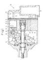
- a swash plate type compressor 11 comprises a cylinder block 12, a front housing 13 coupled to the front end of the cylinder block 12, and a rear housing 15 coupled to the rear end of the cylinder block 12 via a valve forming body 14, and these members 11 through 15 are coupled and fixed to each other by plural through-bolts (not shown), constituting a housing assembly H of the compressor.
- a crank chamber 16 In the housing assembly H, a crank chamber 16, a suction chamber 17, and a discharge chamber 18 are defined. Plural cylinder bores (only one is shown) 19 are formed in the cylinder block 12 and a single-headed piston 20 is housed in each cylinder bore 19 so that a reciprocating motion is enabled.
- the suction chamber 17 and the discharge chamber 18 are selectively communicated with each cylinder bore 19 via various types of flapper valves in the valve forming body 14.
- a drive shaft 21 is penetrated so that a rotational motion is enabled.
- a swash plate 22 is supported by the drive shaft 21 while being housed in the crank chamber 16.
- the swash plate 22 has a land portion 23 in the central part and an outer circumferential portion 24 formed with a thickness thinner than that of the land portion 23, which is surrounded by the outer circumferential portion 24.
- This swash plate 22 is operatively connected to the drive shaft 21 via a hinge mechanism 25 and a lug plate 26 so that the swash plate 22 can synchronously rotate with the drive shaft 21 and tilt with respect to the drive shaft 21 accompanied by a sliding motion in the direction of the axis of the drive shaft 21.
- every piston 20 is operatively connected to the swash plate.
- the swash plate 22 tilting in a required inclination angle rotates together with the drive shaft 21, each piston 20 is forced to reciprocate with a stroke according to the inclination of the swash plate 22, and the cycle, in which refrigerant gas sucked from the suction chamber 17 is compressed and discharged to the discharge chamber 18, is repeated.
- the inclination angle of the swash plate 22 is determined by the interactive balance among various moments such as the moment of the rotational motion based on the centrifugal force when the swash plate rotates, the moment of the spring force based on the biasing action of an inclination reducing spring 29, the moment of the inertia force of the reciprocating motion of the piston 20, the moment of the gas pressure, and so on.
- the moment of the gas pressure is a moment determined based on the internal pressure of the cylinder bore 19 and the internal pressure of the crank chamber 16, which is the back pressure of the piston 20, and is applied to both directions in which the inclination of the swash plate 22 decreases and increases, according to the crank pressure.
- the swash plate type compressor of variable displacement type 11 comprises a control valve 30 in the rear housing 15, and the control valve 30 is interposed on a pressure supply passage 31 that connects the crank chamber 16 with the discharge chamber 18 communicatively. Also, the crank chamber 16 and the suction chamber 17 are connected communicatively by a pressure releasing passage (a throttle passage) 32.
- a pressure releasing passage a throttle passage
- the moment of the gas pressure is changed adequately by adjusting the crank pressure by the opening adjustment of the control valve 30.
- each shoe 27 and 28 has flat surfaces 35 and 36 and spherical surfaces 37 and 38, and the flat surfaces 35 and 36 come into contact with a front surface 39 and a rear surface 40 of the swash plate 22, respectively, and the spherical surfaces come into contact with shoe seats 41 of the piston 20.
- An iron-based material, an aluminum-based material or the like is used for a substrate (base material) 42 of the swash plate 22.
- a similar iron-based material (bearing steel, for example) is used for the shoes 27 and 28, of which the mechanical strength thereof, etc. is taken into account.
- Amorphous hard carbon coatings 43 and 44 are formed on both the front surface 39 and the rear surface 40 of the outer circumferential portion 24 of the swash plate 22 ranging over the whole area in the circumferential direction. These amorphous hard carbon coatings 43 and 44 are formed on worked surfaces 45 and 46 of the outer circumferential portion 24 by a CVD method, a PVD method, or the like. Generally, the amorphous hard carbon coatings 43 and 44 are called a synthetic pseudo-diamond thin coating, a diamond-like carbon (DLC), i-carbon, or the like, and hereinafter are referred to as a DLC coating in this example. These DLC coatings 43 and 44 of the swash plate 22 come into contact with the flat surfaces 35 and 36, respectively, of the shoes 27 and 28 and serve as the sliding surfaces with the shoes 27 and 28 of the swash plate 22.
- DLC diamond-like carbon
- the DLC coatings 43 and 44 have characteristics similar to diamond in physical properties such as hardness, etc. and also have a specific quality characterized in that the hardness is high and the friction coefficient is low. Since the surface of the swash plate 22 has the DLC coatings 43 and 44, that is, has high sliding characteristics excellent in such as abrasion resistance and resistance to seizure, abrasion and seizure occurs less frequently at the sliding portions 47 between the swash plate 22 and the shoes 27 and 28, and the reliability of the swash plate 22 and the shoes 27 and 28, and the compressor 11 itself as a result, is improved. In addition, since the DLC coatings 43 and 44 have good forming accuracy (working accuracy) in coating thickness, surface roughness, etc., such finishing processes as grinding, etc. to ensure the required coating thickness and surface roughness, are not necessary, resulting in a simplified coating forming work and a lower cost.
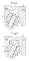
- FIG.3 is an example in which a coating is formed only onto the rear surface of the swash plate.
- the reaction force which is produced when the piston 20 is retracted forcedly to suck the refrigerant gas, is applied mainly to the front surface 39 of the swash plate 22 via the shoe 27 on the front side.
- the reaction force of the compression which is produced when the piston 20 compresses the refrigerant gas to discharge it, is applied mainly to the rear surface 40 of the swash plate 22 via the shoe 28 on the rear side.
- the swash plate 22 and the shoes 27 and 28, respectively are made of different materials
- the swash plate 22 is made of aluminum-based material and the shoes 27 and 28 are made of iron-based material, seizure caused by the so-called "friction phenomenon between the same metal" is unlikely to occur. Therefore, if the fact that the swash plate 22 and the shoes 27 and 28 are made of different materials and the reaction force caused by forced retraction is relatively small is taken into account, there may be the case where the sliding characteristics of the front side of the swash plate 22 need not be improved in particular.
- the DLC coating 44 is formed only on the rear surface 40 of the swash plate 22. Saving the coating forming process on the front side, this structure can reduce the excessive processes for coating forming and the manufacturing cost. In addition, since the DLC coating 44 is formed on the rear surface 40 that needs to have the sliding characteristics of high quality, the probability of occurrence of abrasion and seizure does not increase rapidly and the high reliability of the swash plate 22 and the shoes 27 and 28, and the compressor 11 as a result can be ensured.
- FIG.4 shows an example where coatings are formed on both the flat surfaces of a pair of shoes.
- the DLC coatings 48 and 49 are formed on the entire area of the flat surfaces 35 and 36 of the shoes 27 and 28. Therefore, the flat surfaces 35 and 36 of the shoes 27 and 28 come into contact with the swash plate 22 on the surfaces of the DLC coatings 48 and 49, respectively, and these DLC coatings 48 and 49 serve as the sliding surfaces between the shoes 27 and 28 and the swash plate 22.
- the work of coating forming is simplified and the sliding characteristics of the sliding portion 47 between the swash plate 22 and the shoes 27 and 28 is improved, the reliability of the swash plate 22 and the shoes 27 and 28, and even the compressor 11 as a result, is improved.
- the required area for coating is smaller, resulting in further reduction in cost of materials.
- the DLC coating 49 is formed only on the flat surface 36 of the shoe 28 on the rear side to which the reaction force of compression is applied, and no DLC coating 48 is applied on the front side.
- FIG.5 shows an example in which a coating is formed on the entire surface of the shoes.
- the DLC coatings 50 and 51 are formed on the entire surface of the shoes 27 and 28. Therefore, on the entire surface of the shoe 27 and 28, the surfaces of the DLC coatings 50 and 51 formed on the spherical surfaces 37 and 38 that slide on the shoe seats 41 serve as the sliding surface between the shoes 27 and 28 and the piston 20, and the surfaces of the DLC coatings 50 and 51 formed on the flat surfaces 35 and 36 that slide with respect to the swash plate 22 serve as the sliding surface between the shoes 27 and 28 and swash plate 22.
- a surface treatment (Sn-plate treatment, for example) of the shoe seats 41 of the piston 20 can be avoided, and abrasion or seizure occurs less frequently on not only the sliding portion 47 between the swash plate 22 and the shoes 27 and 28, but also the sliding portion 52 between the shoes 27 and 28 and the pistons 20, therefore, the reliability of not only the swash plate 22 and the shoes 27 and 28 but also the pistons 20 is improved.
- the DLC coatings 50 and 51 can be formed only on the spherical surfaces 37 and 38 of the shoes 27 and 28.
- FIG.6 shows an example in which a coating is formed on the piston.
- the DLC coating 54 is formed on the entire outer surface of the piston 20. Therefore, on the entire outer surface of the piston 20, the surface of the DLC coating 54 formed on the shoe seats 41 on which the shoes 27 and 28 slide serves as the sliding surface between the piston 20 and the shoes 27 and 28, and the surface of the DLC coating 54 formed on the outer circumferential surface 56 of a piston main body 55, that slides on the cylinder block 12, serves as the sliding surface between the piston 20 and the cylinder block 12.
- the sliding characteristics of not only the sliding portion 52 between the shoes 27 and 28 and the piston 20 but also the sliding portion 57 between the piston 20 and the cylinder block 12 are improved and the reliability of the shoes 27 and 28, the piston 20, and the cylinder block 12 is improved. It can also be the case where the DLC coating 54 is formed only on the shoe seats 41 of the piston 20 or only on the outer circumferential surface 56.
- a swash plate type compressor is not restricted to the variable displacement type comprising the piston 20 of single-headed type.
- the DCL coatings 43 and 44 can be formed on both surfaces of a swash plate 62 thereof.
- the sliding characteristics of the swash plate 62 and a shoe 63 are improved and the reliability of components is also improved.
- the location for forming DLC coating can be selected by combining the examples described in the above embodiments adequately and flexibly according to requirement. Examples are shown below.
- Forming of the DLC coating is not restricted to the case where the DLC coatings are formed on the sliding portions 47, 52, and 57 between each component, that is to say, the swash plate 22, shoes 27 and 28, and the piston 20.
- the DLC coating may be formed, for example, on the inner circumferential surface of the hole of the swash plate 22 through which the drive shaft 21 penetrates, the sliding surface between the drive shaft 21 and the swash plate 22, the bearing that supports the drive shaft 21 rotatably, the lip seal that isolates the crank chamber from outside, the hinge mechanism 25, and so on. That is to say, the DLC coating can be formed on any sliding portions that slide on, among comopnents constiting the compressor, while the compressor is in operation.
- the DLC coating is formed on only one side of the sliding surface of each sliding portion 47, 52, and 57, the DLC coating may be formed on the both sides of the sliding portions so that the DLC coatings 43, 44, 48, and 49 are formed, for example, on the both surfaces of the swash plate 22 and the flat surfaces 35 and 36 of the shoes. In this case abrasion or seizure of the parts is made to occur even less frequently.
- the DLC coatings 43, 44, 48 through 51, and 54 are formed on the entire area of the sliding surface, the DLC coating may be formed only on a part of the sliding surface. That is to say, the DLC coating is not required to be formed on the entire area of the sliding surface if high sliding characteristics are ensured.
- the DLC coatings are formed directly on the surface of the substrate (base material) of each component 20, 22, 27, and 28, intermediate layers consisting of a flame-sprayed layer, a plating layer, or the like, may be formed between, for example, the substrate or the DLC coating.
- intermediate layers consisting of a flame-sprayed layer, a plating layer, or the like, may be formed between, for example, the substrate or the DLC coating.
- the coating forming work requires excessive processes compared to the case where only the DLC coating is formed, but the sliding characteristics are maintained by the intermediate layer even if the DLC coatings are worn out by abrasion or seizure. Therefore, if the double-structure comprising a DLC coating and an intermediate layer is adopted, sliding characteristics of a higher quality can be ensured.
- the DLC coating is formed on the entire surface of the front surface 39 and the rear surface 40 of the outer circumferential portion 24 when the DLC coatings 43 and 44 are formed on the swash plate 22, the DLC coating can be formed only on the portion which slides against the shoes 27 and 28.
- the DLC coating is formed on the entire outer surface of the piston 20, the coating can be partially formed on the piston 20 so that the DLC coating is formed only on the outer circumferential surface 56 and the shoe seats 41 of the piston 20.
- the sliding characteristics of the sliding portion can be improved and the work of coating forming can be simplified by forming an amorphous hard carbon coating on the sliding portion where the components of the compressor slide on each other.
Landscapes
- Engineering & Computer Science (AREA)
- Mechanical Engineering (AREA)
- General Engineering & Computer Science (AREA)
- Manufacturing & Machinery (AREA)
- Compressors, Vaccum Pumps And Other Relevant Systems (AREA)
Applications Claiming Priority (2)
| Application Number | Priority Date | Filing Date | Title |
|---|---|---|---|
| JP2000193456 | 2000-06-27 | ||
| JP2000193456A JP2002005013A (ja) | 2000-06-27 | 2000-06-27 | 斜板式圧縮機 |
Publications (2)
| Publication Number | Publication Date |
|---|---|
| EP1167761A2 true EP1167761A2 (de) | 2002-01-02 |
| EP1167761A3 EP1167761A3 (de) | 2003-07-16 |
Family
ID=18692447
Family Applications (1)
| Application Number | Title | Priority Date | Filing Date |
|---|---|---|---|
| EP01114766A Withdrawn EP1167761A3 (de) | 2000-06-27 | 2001-06-25 | Taumelscheibenverdichter |
Country Status (3)
| Country | Link |
|---|---|
| US (1) | US20010054352A1 (de) |
| EP (1) | EP1167761A3 (de) |
| JP (1) | JP2002005013A (de) |
Cited By (4)
| Publication number | Priority date | Publication date | Assignee | Title |
|---|---|---|---|---|
| FR2838789A1 (fr) * | 2002-02-25 | 2003-10-24 | Luk Fahrzeug Hydraulik | Machine a piston alterne |
| EP1712790A1 (de) * | 2005-04-13 | 2006-10-18 | Kabushiki Kaisha Toyota Jidoshokki | Taumelscheibenverdichter |
| WO2008014737A1 (de) * | 2006-07-29 | 2008-02-07 | Ixetic Mac Gmbh | Vorrichtung zum ankoppeln eines kolbens an eine ringscheibe |
| WO2015176988A1 (de) * | 2014-05-23 | 2015-11-26 | Mahle International Gmbh | Axialkolbenmaschine |
Families Citing this family (11)
| Publication number | Priority date | Publication date | Assignee | Title |
|---|---|---|---|---|
| DE102005023554B4 (de) | 2005-05-21 | 2018-04-05 | Schaeffler Technologies AG & Co. KG | Taumelscheibengetriebe, insbesondere für einen Axialkolbenkompressor |
| JP2007056720A (ja) * | 2005-08-23 | 2007-03-08 | Sanden Corp | 斜板式圧縮機 |
| JP2007056721A (ja) * | 2005-08-23 | 2007-03-08 | Sanden Corp | 斜板式圧縮機 |
| JP5033432B2 (ja) | 2007-01-30 | 2012-09-26 | 株式会社豊田自動織機 | 摺動部品 |
| DE102007047629A1 (de) * | 2007-04-13 | 2008-10-16 | Stein, Ralf | Verfahren zum Aufbringen einer hochfesten Beschichtung auf Werkstücke und/oder Werkstoffe |
| JP2008267251A (ja) * | 2007-04-19 | 2008-11-06 | Sanden Corp | 圧縮機 |
| JP4831428B2 (ja) * | 2007-05-25 | 2011-12-07 | 株式会社豊田自動織機 | 圧縮機摺動部材の非晶質硬質炭素皮膜の成膜方法とその方法で成膜された圧縮機摺動部材及びその製造装置 |
| US8962143B2 (en) | 2008-10-27 | 2015-02-24 | Taiho Kogyo Co., Ltd. | PTFE-based sliding material, bearing, and method for producing PTFE-based sliding material |
| JP6133014B2 (ja) * | 2012-02-28 | 2017-05-24 | ナブテスコ株式会社 | 油圧ポンプ |
| US10273990B2 (en) * | 2015-01-14 | 2019-04-30 | Hamilton Sundstrand Corporation | Fixed wobbler for hydraulic unit |
| CA3030899A1 (en) * | 2019-01-22 | 2020-07-22 | Matthew Hwong | Actuator for a needle |
Citations (2)
| Publication number | Priority date | Publication date | Assignee | Title |
|---|---|---|---|---|
| JPH08199327A (ja) | 1995-01-27 | 1996-08-06 | Taiho Kogyo Co Ltd | 斜板式コンプレッサーの斜板 |
| JPH11193780A (ja) | 1997-12-26 | 1999-07-21 | Toyota Autom Loom Works Ltd | 片頭ピストン型斜板式圧縮機および斜板の製造方法 |
Family Cites Families (4)
| Publication number | Priority date | Publication date | Assignee | Title |
|---|---|---|---|---|
| JP3039762B2 (ja) * | 1995-03-07 | 2000-05-08 | 株式会社豊田自動織機製作所 | 往復動型圧縮機 |
| JP3568061B2 (ja) * | 1995-05-17 | 2004-09-22 | 大豊工業株式会社 | 斜板式コンプレッサーの斜板及び斜板とシューとの組合わせ |
| JP4023872B2 (ja) * | 1997-06-26 | 2007-12-19 | 大豊工業株式会社 | 斜板式コンプレッサー用斜板 |
| JP2000179453A (ja) * | 1998-12-17 | 2000-06-27 | Taiho Kogyo Co Ltd | 斜板式コンプレッサーの斜板 |
-
2000
- 2000-06-27 JP JP2000193456A patent/JP2002005013A/ja active Pending
-
2001
- 2001-06-20 US US09/885,778 patent/US20010054352A1/en not_active Abandoned
- 2001-06-25 EP EP01114766A patent/EP1167761A3/de not_active Withdrawn
Patent Citations (2)
| Publication number | Priority date | Publication date | Assignee | Title |
|---|---|---|---|---|
| JPH08199327A (ja) | 1995-01-27 | 1996-08-06 | Taiho Kogyo Co Ltd | 斜板式コンプレッサーの斜板 |
| JPH11193780A (ja) | 1997-12-26 | 1999-07-21 | Toyota Autom Loom Works Ltd | 片頭ピストン型斜板式圧縮機および斜板の製造方法 |
Cited By (6)
| Publication number | Priority date | Publication date | Assignee | Title |
|---|---|---|---|---|
| FR2838789A1 (fr) * | 2002-02-25 | 2003-10-24 | Luk Fahrzeug Hydraulik | Machine a piston alterne |
| EP1712790A1 (de) * | 2005-04-13 | 2006-10-18 | Kabushiki Kaisha Toyota Jidoshokki | Taumelscheibenverdichter |
| US7406912B2 (en) | 2005-04-13 | 2008-08-05 | Kabushiki Kaisha Toyota Jidoshokki | Swash plate compressor |
| WO2008014737A1 (de) * | 2006-07-29 | 2008-02-07 | Ixetic Mac Gmbh | Vorrichtung zum ankoppeln eines kolbens an eine ringscheibe |
| US8430018B2 (en) | 2006-07-29 | 2013-04-30 | ixeric MAC GmbH | Device for coupling a piston to an annular disk |
| WO2015176988A1 (de) * | 2014-05-23 | 2015-11-26 | Mahle International Gmbh | Axialkolbenmaschine |
Also Published As
| Publication number | Publication date |
|---|---|
| US20010054352A1 (en) | 2001-12-27 |
| EP1167761A3 (de) | 2003-07-16 |
| JP2002005013A (ja) | 2002-01-09 |
Similar Documents
| Publication | Publication Date | Title |
|---|---|---|
| KR100493218B1 (ko) | 슬라이딩재 및 슬라이딩 장치 | |
| EP1167761A2 (de) | Taumelscheibenverdichter | |
| US6584886B2 (en) | Compressor | |
| EP0844390B1 (de) | Schrägscheibenverdichter mit einer Schrägscheibe aus hochverschleissfestem Material | |
| US6217295B1 (en) | Swash plate type compressor | |
| US6581507B2 (en) | Single-headed piston type swash plate compressor | |
| US6666128B2 (en) | Swash plate in swash plate type compressor | |
| US6640690B2 (en) | Swash plate type compressor and shoe for the same | |
| US20020046647A1 (en) | Compressors | |
| US20020046646A1 (en) | Compressors | |
| EP0943800A1 (de) | Taumelscheibenverdichter | |
| US6761106B2 (en) | Swash plate for compressor | |
| CN100425833C (zh) | 旋转斜盘式压缩机 | |
| WO2009157267A1 (ja) | ピストン式圧縮機におけるシュー | |
| KR101452498B1 (ko) | 압축기 | |
| US20090097990A1 (en) | Swash plate type compressor | |
| EP1092873A2 (de) | Zylinderbohrung eines Taumelscheibenkompressors mit Nuten | |
| EP0992682A2 (de) | Kolbenverdichter | |
| JP2002089439A (ja) | 斜板式圧縮機 |
Legal Events
| Date | Code | Title | Description |
|---|---|---|---|
| PUAI | Public reference made under article 153(3) epc to a published international application that has entered the european phase |
Free format text: ORIGINAL CODE: 0009012 |
|
| 17P | Request for examination filed |
Effective date: 20010625 |
|
| AK | Designated contracting states |
Kind code of ref document: A2 Designated state(s): AT BE CH CY DE DK ES FI FR GB GR IE IT LI LU MC NL PT SE TR |
|
| AX | Request for extension of the european patent |
Free format text: AL;LT;LV;MK;RO;SI |
|
| PUAL | Search report despatched |
Free format text: ORIGINAL CODE: 0009013 |
|
| AK | Designated contracting states |
Designated state(s): AT BE CH CY DE DK ES FI FR GB GR IE IT LI LU MC NL PT SE TR |
|
| AX | Request for extension of the european patent |
Extension state: AL LT LV MK RO SI |
|
| AKX | Designation fees paid |
Designated state(s): DE FR IT |
|
| STAA | Information on the status of an ep patent application or granted ep patent |
Free format text: STATUS: THE APPLICATION IS DEEMED TO BE WITHDRAWN |
|
| 18D | Application deemed to be withdrawn |
Effective date: 20031231 |