EP1167818B1 - Transmission planétaire à rapport variable - Google Patents
Transmission planétaire à rapport variable Download PDFInfo
- Publication number
- EP1167818B1 EP1167818B1 EP01660115A EP01660115A EP1167818B1 EP 1167818 B1 EP1167818 B1 EP 1167818B1 EP 01660115 A EP01660115 A EP 01660115A EP 01660115 A EP01660115 A EP 01660115A EP 1167818 B1 EP1167818 B1 EP 1167818B1
- Authority
- EP
- European Patent Office
- Prior art keywords
- planetary
- planetary gear
- gears
- gear
- gear transmission
- Prior art date
- Legal status (The legal status is an assumption and is not a legal conclusion. Google has not performed a legal analysis and makes no representation as to the accuracy of the status listed.)
- Expired - Lifetime
Links
- 230000005540 biological transmission Effects 0.000 title claims abstract description 144
- 230000008878 coupling Effects 0.000 claims abstract description 12
- 238000010168 coupling process Methods 0.000 claims abstract description 12
- 238000005859 coupling reaction Methods 0.000 claims abstract description 12
- 230000007246 mechanism Effects 0.000 claims description 9
- 239000012530 fluid Substances 0.000 claims description 2
- 238000006073 displacement reaction Methods 0.000 description 9
- 238000000034 method Methods 0.000 description 6
- 230000008901 benefit Effects 0.000 description 3
- 239000003638 chemical reducing agent Substances 0.000 description 3
- 238000002485 combustion reaction Methods 0.000 description 3
- 230000008859 change Effects 0.000 description 2
- 238000010276 construction Methods 0.000 description 2
- 230000009466 transformation Effects 0.000 description 2
- 230000006835 compression Effects 0.000 description 1
- 238000007906 compression Methods 0.000 description 1
- 230000003247 decreasing effect Effects 0.000 description 1
- 239000007788 liquid Substances 0.000 description 1
- 230000004048 modification Effects 0.000 description 1
- 238000012986 modification Methods 0.000 description 1
- 230000005855 radiation Effects 0.000 description 1
- 230000009467 reduction Effects 0.000 description 1
- XLYOFNOQVPJJNP-UHFFFAOYSA-N water Substances O XLYOFNOQVPJJNP-UHFFFAOYSA-N 0.000 description 1
Images


Classifications
-
- F—MECHANICAL ENGINEERING; LIGHTING; HEATING; WEAPONS; BLASTING
- F16—ENGINEERING ELEMENTS AND UNITS; GENERAL MEASURES FOR PRODUCING AND MAINTAINING EFFECTIVE FUNCTIONING OF MACHINES OR INSTALLATIONS; THERMAL INSULATION IN GENERAL
- F16H—GEARING
- F16H3/00—Toothed gearings for conveying rotary motion with variable gear ratio or for reversing rotary motion
- F16H3/44—Toothed gearings for conveying rotary motion with variable gear ratio or for reversing rotary motion using gears having orbital motion
- F16H3/72—Toothed gearings for conveying rotary motion with variable gear ratio or for reversing rotary motion using gears having orbital motion with a secondary drive, e.g. regulating motor, in order to vary speed continuously
-
- F—MECHANICAL ENGINEERING; LIGHTING; HEATING; WEAPONS; BLASTING
- F16—ENGINEERING ELEMENTS AND UNITS; GENERAL MEASURES FOR PRODUCING AND MAINTAINING EFFECTIVE FUNCTIONING OF MACHINES OR INSTALLATIONS; THERMAL INSULATION IN GENERAL
- F16H—GEARING
- F16H3/00—Toothed gearings for conveying rotary motion with variable gear ratio or for reversing rotary motion
- F16H3/44—Toothed gearings for conveying rotary motion with variable gear ratio or for reversing rotary motion using gears having orbital motion
- F16H3/46—Gearings having only two central gears, connected by orbital gears
- F16H3/48—Gearings having only two central gears, connected by orbital gears with single orbital gears or pairs of rigidly-connected orbital gears
- F16H3/52—Gearings having only two central gears, connected by orbital gears with single orbital gears or pairs of rigidly-connected orbital gears comprising orbital spur gears
- F16H3/56—Gearings having only two central gears, connected by orbital gears with single orbital gears or pairs of rigidly-connected orbital gears comprising orbital spur gears both central gears being sun gears
-
- F—MECHANICAL ENGINEERING; LIGHTING; HEATING; WEAPONS; BLASTING
- F16—ENGINEERING ELEMENTS AND UNITS; GENERAL MEASURES FOR PRODUCING AND MAINTAINING EFFECTIVE FUNCTIONING OF MACHINES OR INSTALLATIONS; THERMAL INSULATION IN GENERAL
- F16H—GEARING
- F16H3/00—Toothed gearings for conveying rotary motion with variable gear ratio or for reversing rotary motion
- F16H3/44—Toothed gearings for conveying rotary motion with variable gear ratio or for reversing rotary motion using gears having orbital motion
- F16H3/72—Toothed gearings for conveying rotary motion with variable gear ratio or for reversing rotary motion using gears having orbital motion with a secondary drive, e.g. regulating motor, in order to vary speed continuously
- F16H3/727—Toothed gearings for conveying rotary motion with variable gear ratio or for reversing rotary motion using gears having orbital motion with a secondary drive, e.g. regulating motor, in order to vary speed continuously with at least two dynamo electric machines for creating an electric power path inside the gearing, e.g. using generator and motor for a variable power torque path
Definitions
- the invention relates to a planetary gear transmission with an variable transmission ratio, without a ring gear wheel, and comprising: a first sun gear arranged on a first operating shaft and at least one first planetary gear connectable thereto; a second sun gear arranged on a second operating shaft and at least one second planetary gear connectable thereto; planetary shafts, rigidly attaching each of the second planetary gears to one of the first planetary gears, in which case the first and the second planetary gears form first pairs of planetary gears, in which the planetary gears rotate at the same angular speed; and a planetary carrier that is common for the first and second planetary gears.
- the publication US-3 823 620 and its priority document FR-2 138 263 relates to an automatically and continuously variable transmission for changing the velocity of a driven shaft relative to the velocity of a drive shaft.
- the transmission includes three epicyclic trains, namely an input train, a control train and an intermediate train.
- the input train includes an element driven by the drive shaft and another element connected to the driven shaft.
- the control train is a high ratio train including a planetary gear system, the planet-carrier of which is driven by an electric motor of variable velocity and low power, of the order of 1 percent of the power to be transmitted from the drive shaft to the driven shaft.
- a first sun-wheel of the planetary gear system is connected to the third element of the input train and a second-sun-wheel is connected to an element of the intermediate train, the two remaining elements of which are respectively connected to the input train and to either of the drive or the driven shafts.
- the publication US-3 298 251 discloses a constant-speed drive according to the preamble of claim 1 comprising an input shaft element for connection to a prime mover operable at a variable speed in a predetermined direction, a constant speed shaft element for connection to a load required to be driven at a constant speed in a predetermined direction, a third element, a differential gear drive by which the three said elements are operatively connected, a constant displacement hydraulic machine drivingly connected to said third element, a variable-displacement hydraulic machine drivingly connected to one of said shaft elements, a pair of hydraulic lines connecting said variable displacement hydraulic machine in a closed hydraulic circuit with said constant-displacement hydraulic machine, governor means responsive to a speed error of the constant-speed element compared with the required constant speed and operative to so vary the displacement of said variable-displacement machine between a positive maximum and a negative maximum as to reduce such speed error, an independent hydraulic pressurising device having a low-pressure inlet and a high-pressure outlet, starter-selection means for connecting the inlet of
- the transmission ratio of the planetary gear transmission is adjusted by braking the planetary carrier either by means of a friction brake, which is coupled either between the planetary carrier and the housing of the device or between the planetary carrier and the input shaft, or by arranging belt transmission between the planetary carrier and the input shaft.
- a friction brake which is coupled either between the planetary carrier and the housing of the device or between the planetary carrier and the input shaft, or by arranging belt transmission between the planetary carrier and the input shaft.
- the object of the invention is to realize a mechanical gear transmission with a transmission ratio that can be variable or steplessly adjusted within a wide marginal, while one or several of the transmission ratios can be locked at a fixed value and again released according to the situation of usage.
- a second object of the invention is this kind of variable, mechanical gear transmission that achieves a minimal loss in efficiency.
- a third object of the invention n is this kind of stepless mechanical gear transmission, where a stepless or sliding change in the transmission ratio can be achieved by many different, alternative ways.
- Yet another object of the invention is this kind of gear transmission that is simple in structure and possibly small in size.
- a second advantage of the invention is that only a slight amount of power is consumed in said adjusting of the transmission ratio, and according to a preferred embodiment of the invention, the power loss is made nearly nonexistent.
- a third advantage of the invention is the possibility to real ize the planetary gear transmission, when necessary, in a form where one or several of the transmission ratios can during operation and according to the situation at hand be locked in a fixed position and again released to be variable by following a simple procedure.
- the planetary gear transmission according to the invention When locked in a fixed position, the planetary gear transmission according to the invention operates in principle in similar fashion as a gear transmission with a fixed transmission ratio, i.e. accurately and always with minimal power losses.
- the stepless planetary gear transmission according to the invention is extremely simple and secure in operation.
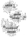
- the drawings illustrate planetary gear transmissions where the transmission ratio is variable. In the text no difference is made between the pinions and the gears, because the transmissions can be used in both directions. Some of the drawings illustrate planetary gear transmissions where the variable transmission ratio can, when necessary, be locked at a fixed value or values.
- the power and the torque are conducted to the planetary gear transmission by means of rotary input shafts 7 or 8 connected to the sun gears, or via a planetary carrier 5, from the primary motor M illustrated in some of the drawings, which primary motor can in principle be any kind of motor or other power source.
- the power and the torque are conducted out of the planetary gear transmission on the output shafts 8 or 7 connected to the sun gears, or from the planetary carrier 5.
- either one of the shafts marked with the reference numbers 7 and 8 can be the input shaft, in which case the other is the output shaft, i.e. the gear transmission can transmit power and torque to both directions.
- this planetary gear transmission there is provided at least one first sun gear 11 and, connected thereto, at least one first planetary gear 1 as well as a planetary carrier 5 connecting the planetary gear or gears, more precisely the planetary gears shafts 6, said planetary carrier being arranged to be rotatable around the common rotary axis line L1 of the input and output shafts, the speed of rotation ⁇ , i.e. angular velocity whereof is controlled by means of a suitable braking mechanism or coupling means 50 connected thereto.
- the planetary gear transmission according to the invention does not include ring gear wheels, i.e. a group of planetary gears arranged on a given plane - neither the first planetary gears 1 nor the second planetary gears 2 - are not simultaneously connected to a gear wheel that were concentric with the sun gears.
- the planetary gear of the invention does not have any ring gear wheel, but the group of first planetary gears 1 is only connected to the externally or internally toothed sun gear, and the second group of planetary gears 2 is only connected to the externally or internally toothed sun gear, and/or the planetary gears are mutually connected.
- the term 'connect' and possible variations thereof are used to mean the capability of transmitting the power and torque of the rotary motion between the gear wheels, caused by the mutually meshing toothing of said gear wheel.
- two gear wheels are mutually connected, when the rotary motion of one gear wheel sets also the second gear wheel that is immediately connected thereto in rotary motion, by intermediation of the meshing toothings of the wheels, at the same angular velocity or at another angular velocity.
- references 1 and 2 denote to the first and second planetary gears in general
- the references 3 and 4 denote to the third and fourth planetary gears in general
- the reference B1 denotes to the primary pair of planetary gears in general.
- the specified references 1a, 1b, 2a; B1a etc. are only used when single corresponding parts must be distinguished for the sake of clarity.
- neither of the sun gears 11, 12 is braked with respect to the housing 31, but they are rigidly attached to the first operating shaft and respectively to the second operating shaft 7, 8.
- the planetary gear transmission of the invention - according to the first principle of structure - comprises at least one second planetary gear 2, which is placed on the shaft 6, rigidly attached to one of the first planetary gears 1, in which case said first and second planetary gear constitute a first pair B1 of planetary gears, as in figure 3. If the planetary gear transmission includes two first planetary gears 1a and 1b, and two second planetary gears 2a and 2b, they form, on two shafts 6, two first pairs B1a and B1b of planetary gears, as is illustrated in figures 1A and 2.
- Figure 1B illustrates a structure provided with four first planetary gears 1a, 1b, 1c and 1d, and two second planetary gears 2a, 2b, 2c and 2d, so that there are formed four pairs B1a, B1b, B1c and B1d of planetary gears, i.e. generally a pair B1 of planetary gears.
- Said two pairs B1a and B1b of planetary gears, or respectively four pairs B1a, B1b, B1c and B1d are arranged in parallel with respect to the moment transmitted through the gear transmission n. It should be appreciated that said pairs of planetary gears arranged in parallel can also be three or more than four.
- first and second planetary gears 1 and 2 non-rotatably attached to the common shaft 6, rotate together at the same angular velocity, i.e. the shaft 6 of the pair of planetary gears, complete with both planetary gears 1 and 2, i.e.6+1a+2a, 6+1b+2b, etc., rotates around the common planetary carrier 5.
- the above mentioned first sun gear 11 is axially attached to a first operating shaft 7 or to a second operating shaft 8, so that the rotary motion of the sun gear is equal to or opposite to the rotary motion of said shaft.
- a planetary gear conforming to these structural principles also comprises a second sun gear 12, which is connected to the second set of planetary gears and is axially attached to the second operating shaft 8 or respectively to the first operating shaft 7, so that the rotary motion of the sun gear is equal or opposite to the rotary motion of said shaft. Consequently, the first planetary gears 1 of each first pair B1 of planetary gears - secondary planetary gears in the examples illustrated in the drawings - are connected to the first sun gear 11, and the second planetary gears 2 - primary planetary gears in the examples illustrated in the drawings - are connected to the second planetary gear 12.
- the planetary gear transmission comprises one or more coupling means 50 in order to take the whole rotary power F1, F2 or part F2, F3 thereof out of the planetary gear and/or respectively in order to feed the whole rotary power F1, F2 or part F2, F3 thereof to the planetary gear, in a way to be described in more detail below.
- Said power output and/or input is carried out according to either of the alternative ways described in the following.
- the rotary power F1, F2 or part F2, F3 thereof proceeds via the first or the second operating shaft 7; 8 to the planetary gear or out thereof.
- the rotary power F1, F2 or part F2, F3 thereof proceeds via the planetary carrier 5 to the planetary gear or out thereof.
- the planetary gear transmission comprises at least one operation element 15, 16, 17, 23, 24, 25, 26, 37 in order to adjust the rotary velocity ⁇ of the planetary carrier 5 at least in a first position where the planetary carrier is locked to be stationary, and in a second position, where the planetary carrier is freely rotatable.
- the coupling means 50 are ring toothings 22a of the planetary carrier, together with countergear wheels 22b connected thereto, or direct connections 22c, which are continuously connected to the planetary carrier, in which case said transmission of the powers F1, F2, F3 to or from the planetary carrier is enabled by using a separate adjusting element or corresponding means.
- the described structural embodiment is suited to a continuously stepless adjusting.
- the functional diameter Pa1 of the first sun gear 11 must be different from the functional diameter Pa2 of the second sun gear 12 Pa2, and in addition, in the planetary gear pairs B1 the functional diameter Pp1 of the first planetary gears 1 is respectively different from the functional en diameter Pp2 of the second planetary gears 12.
- the functional diameter Pa1 of the first sun gear 11 is larger than the functional diameter Pa2 of the second sun gear 12
- the functional diameter Pp1 of the first planetary gears 1 smaller than the functional diameter Pp2 of the second planetary gears 12.
- the planetary gears 1 and 2 of the first planetary gear pairs B1a, B1b, B1c, B1d in case there are two or more pairs, have the same ratio Pp1:Pp2 of the functional diameters, in order to enable the different-sized planetary gears rotating at different angular velocities to be connected to common sun gears.
- the simplest way to realize this is to make the first set of planetary gears 1a, 1b, 1c etc. and the second set of planetary gears 2a, 2b, 2c etc. mutually equal in size with respect to the functional diameter.
- the common axial line L1 of the first and second operating shaft 7, 8 and the center lines L2 of the shafts 6 of the planetary gears are parallel, and the axial lines L2 of the planetary gears are placed at equal distances from the axial line L1 of the first and second operating shaft, and all first planetary gear pairs rotate at the same angular velocity.
- the transmission is direct, so to speak. This means that the transmission ratio varies steplessly within the range 10:1 - 1:1 or within the range 1:10 - 1:1.
- ⁇ O is the angular velocity of the output shaft, i.e. the second operating shaft 8
- ⁇ I is the angular velocity of the input shaft, i.e. the first operating shaft 7
- ⁇ is the circumferential velocity of the planetary carrier 5
- P is the transmission ratio, when the possible rotation of the planetary carrier is left out, i.e. it is stationary.
- the speed of rotation ⁇ of the planetary carrier 5 can also be raised higher than that of the first operating shaft 7 and/or the speed of rotation R T of the second operating shaft 8, i.e. ⁇ > R T , in which case the maximum transmission ratio P max is increased or decreased with respect to the limit transmission ratio P limit , depending on whether the gear in question is a reduction or increaser.
- the latter value is obtained in a situation where the velocity of the planetary carrier 5 is increased in the same first direction D1 in which the input shaft, i.e. the first operating shaft rotates, i.e. ⁇ > R T ; this is called the third position of the planetary carrier.
- it is possible not only to stop the planetary carrier 5, but to force it or accelerate its speed of rotation ⁇ in a direction D2, opposite to the rotation R T of the first operating shaft, i.e. in this case the input shaft, which means that ⁇ R M .
- Said other velocity R M can, in the first place, be between zero and -R T , i.e. 0 > R M > -R T , which means the same velocity as that of the input shaft, but in the opposite direction D2. This is the fourth position of the planetary carrier.
- Said latter alternatives explained above are used mainly for adjusting the axial torque rendered by the gear transmission, rather than its transmission ratio P.
- the planetary gear transmission according to the invention may - according to the principles of another structure - comprise at least one shaft structure 30a, where for example one diagonal shaft 18a is attached, by a first universal joint 13, to a second operating shaft 8 or respectively to a first operating shaft 7, and by a second universal joint 14 respectively attached to the shaft 6 of the first planetary gear 1, as is illustrated in figure 4.
- the diagonal shaft 18a of the shaft structure rotates at the same angular velocity R T as the input shaft /output shaft, and further said first planetary gears 1 rotate at the same angular velocity as the diagonal shaft.
- the limit transmission ratio P limit 1:1, in which case the transmission ratio varies steplessly within the range 4:1 - 1:1 or within the range 1:4 - 1:1.
- said planetary gear may also comprise a second or several shaft structures 30b, the diagonal shafts 18b whereof are attached to the first operating shaft 8 by universal joints 13, or respectively to the second operating shaft 7.
- the structure comprises other first planetary gears 1, to the shafts 6 whereof the diagonal shafts 18b are attached by universal joints 14.
- the diagonal shafts 18; 18a, 18b etc. all rotate at the same angular velocity, and at the same velocity R T as the input or output shafts and at the same velocity as said first planetary gears.
- said first direction of rotation D1 of the planetary carrier is the same as the speed of rotation R T of the first operating shaft, and the same as the speed of rotation R L of the second operating shaft, because between the first and the second operating shaft, there is an odd number of symmetrical planetary gear pairs B1.
- the first rotary direction D1 of the planetary carrier is opposite to the rotary direction and velocity R L of the second operating shaft.
- the speed of rotation of the planetary carrier 5 can be steplessly i.e. slidably maintained at any value between said values, in other words 0 ⁇ ⁇ ⁇ R T .
- one common planetary carrier 5 rotates in some cases, for instance in a situation where the other operating shaft has a high load, while the input shaft rotates at a relatively high speed in the other direction D2, which is opposite to said first direction, the planetary carrier is braked also in this direction, when necessary, down to another velocity ⁇ ⁇ R M , which may in magnitude also be slidable within the range 0 ⁇ ⁇ ⁇ -R T , although generally R M ⁇ -R T .
- ⁇ ⁇ R M which may in magnitude also be slidable within the range 0 ⁇ ⁇ ⁇ -R T , although generally R M ⁇ -R T .
- the planetary gear transmission according to the invention is used so that at each given moment, the transmission ratio P is chosen to be or allowed to be set at a given, exact value, from a basically infinite number of stepless transmission ratios. Hence, nothing else is predetermined, except for the extreme values and adjusting method of the transmission ratios.
- the adjusting of the rotation velocity of the planetary carrier can first of all be arranged by braking it either by an electric generator 15 or by a hydraulic or pneumatic pump 16, which can be an air turbine or a liquid turbine, or by a friction brake 17 or a spring 28, so that energy is accumulated therein, to be consumed later or in another purpose, or by a combination thereof.
- the use of an electric generator and pneumatic or hydraulic pumps is advantageous, because then the energy separated in the braking can be stored in an electric or pressure accumulator 10, and/or the energy separated in the braking can be conducted to the output shaft 7, 8, or by means of a supplementary motor 25, by intermediation of gear wheels 19a and 19b, as is illustrated in figure 1A, or it can be conducted to the power mains 35, as is shown in figure 2.
- the electric or pressure accumulator 10 is connected to the generator 16 or pump 15 by conduits 34 and further to the electric motor 16 or hydraulic or pneumatic motor 15, as well as to a possible AC inverter 24 or torque converter 23 by conduits 34, such as electric wires or pipes.
- said braking mechanisms 15, 16, 17 are advantageously made so that they function equally well in both rotary directions of the planetary carrier, i.e. both in the first rotary direction D1 and in the second, opposite rotary direction D2.
- the second gear wheel 19a is arranged on the supplementary motor shaft, and the second gear wheel 19a is arranged on the output shaft 7, 8.
- the supplementary motor 25 when running raises the power of the output shaft 7, 8. and consequently there is hardly any power loss, except for what is caused by the internal efficiency of the electric, hydraulic or pneumatic components.
- a suitable speed of rotation i.e.
- the axial torque converter included in the supplementary motor, or a combination of an AC inverter and supplementary motor, is connected by conduits 33, such as electric wires or fluid pipes, to the pump 16 or to the electric generator 17.
- the adjusting of the rotation velocity of the planetary carrier can be arranged by accelerating it either by means of an electric motor 15 or a hydraulic or pneumatic motor 16, or by a combination thereof.
- the energy-accumulating spring 28 mentioned in the previous chapter can now be used for increasing the power F1 or F2, F3 to be fed in the planetary gear transmission.
- the use of an electric, pneumatic or hydraulic motor is advantageous because in that case the energy that is earlier accumulated in an electric or pressure accumulator 10 can now be utilized and fed in the planetary carrier 5.
- the above described arrangement is particularly advantageous, because in principle the electric motor and the electric generator are one and the same apparatus, i.e. a combined electric motor and generator 15, and in principle the hydraulic or pneumatic motor and the pump are one and the same apparatus, i.e.
- a combined hydraulic /pneumatic motor and pump 16 a known electric motor and generator combinations 15 and/or a combined hydraulic/pneumatic motor and pump 16. It is also possible to use any other secondary motor 26 in order to realize the above-described functions.
- said motor and generation combination, said motor and pump combination and secondary motor, as well as a possible torque converter or AC inverter are called braking and accelerating mechanisms 15, 16; 26; 23; 24, 25, 27, 28. It should be understood that even if the braking and accelerating mechanisms 15, 16, 26; 23; 24, 25, 27, 28 are defined, the practical application may be such that only one of these is realized.
- the definition braking and accelerating mechanism means that when necessary, the apparatus is capable of both of these mutually opposite functions.
- the planetary gear transmission according to the invention can be used for instance in wind power stations in a way that shall be illustrated with respect to figure 2.
- the employed primary motor M is the wind power station rotor accumulating wind energy, i.e. rotation power F1, the axis of which rotor constitutes the input shaft, i.e. the first operating shaft 7.
- the primary generator G To the output shaft, i.e. to the second operating shaft 8, there is connected the primary generator G, and in addition, to the planetary carrier 5 there is connected for example ring toothings 22a and countergear wheels 22b, as well as possible additional gear wheels by using a secondary generator 15, so that the transmission is designed as an increaser, different from the drawings.
- the rotary forces F2, F3 are taken out of the planetary gear transmission.
- the primary generator G and the secondary generator 15 are adjusted so that the speed of rotation of the primary generator G feeding electric power to the power mains 35 remains constant at an accuracy required of the mains frequency, and the secondary generator 15 feeds power to the mains, while the wind velocity is higher than the optimum velocity, and serves as an auxiliary motor, i.e. accelerates the rotation of the planetary carrier, while the wind velocity is lower than the optimum velocity.
- the ratio of the forces F2 and F3 fed in the planetary gear transmission can be adjusted between the motors 25 and 15 or 26, either electrically by a suitable control unit, such as an AC inverter 24 or a voltage and/or current adapter, viscous coupling, an equalizer or differential gear or Torsen-gear transmission, all of which are referred to by the reference number 27.
- a suitable control unit such as an AC inverter 24 or a voltage and/or current adapter, viscous coupling, an equalizer or differential gear or Torsen-gear transmission, all of which are referred to by the reference number 27.
- a start wire is connected to rotate the input shaft 8, 7, and between the input shaft and the planetary carrier, there is arranged a spring 28, such as a spiral spring.
- the spring 28 accumulates energy, and when pulling the start wire for the second time, the energy accumulated in the spring is released, in which case the motor to be started obtains the sum of the spring force and the manual pulling force. This makes the starting easier, particularly if the required force for overtaking the compression stroke of the combustion engine is high.
- the braking of the planetary carrier 5 is controlled by means of an adjuster or controller, not illustrated in the drawings, which can represent any known or new type and which keeps the rotation velocity ⁇ of the planetary carrier at a such a value that the speed of rotation R L of the output shaft is set at the desired value.
- the chosen type of the adjuster/controller is affected by the type of the primary motor M, as well as the target of usage of both the motor and the gear arrangement.
- the motor-generator 15, the motor-pump 16, the secondary motor 26 and another, possible auxiliary brake 17 can be placed directly on the circumference of the planetary carrier 5, as is seen in figures 1A and 3-5, or by intermediation of the gear wheels 22a, 22b, as is seen in figure 2.
- the planetary gear transmission according to the invention may comprise third planetary gears 3 and/or fourth planetary gears 4, which are connected to the first sun gear 11 and to the first planetary gears 1 arranged therebetween, and/or to the second sun gear 12 and the second planetary gears 2 arranged therebetween, as is shown in figure 5.
- These rotary planetary gears 3, 4 that rotate independently of the rest of the planetary gears do not change the transmission ratio, but when necessary, they can be used to mutually adjust the rotary directions and/or circumferential velocities of the other gear wheels.
- the third planetary gears 3a - and possible additional third planetary gears 3b and 3c - as well as the fourth planetary gears 4a having a difference functional diameter as compared to them - as well as the possible, additional fourth planetary gears 4b and 4c - can be interconnected by common shafts, so that the third planetary gears 3a, 3b, 3c and the fourth planetary gears 4a, 4b, 4c form first planetary gear pairs B1, second planetary gear pairs B2, third planetary gear pairs B3 or even more planetary gear pairs, in each of which the planetary gears 3a and 4a, 3b and 4b, 3c and 4c rotate at the same angular velocity, but in different planetary gear pairs at different angular velocities.
- Said planetary gear pairs B1, B2 and B3 etc. are arranged in series with the first or second planetary gear 1 or 2 or with the first planetary gear pair B1 and with each other, as is schematically illustrated in figure 6.
- the obtained total transmission ratio is for instance [Pa1/Pp1]x[PP2/Pp3]x[Pp4/Pp5]x[Pp6/Pp7]x[Pp7/Pa2], so that the obtained extreme values P max and P min of the transmission ratio P can be for example 40:1 or 1:40 or higher or respectively lower.
- the limit transmission ratio P limit is 1:1 and the maximum transmission ratio P max also is defined in a first and/or second direction D1, D2 from the velocity of the planetary carrier, as is explained above.
- the above described braking and accelerating mechanisms 15, 16, 26 of the planetary carrier 5 can be placed either between the planetary carrier 5 and the housing 31 of the gear arrangement, as is shown by unbroken lines in figures 1A-4 and 5, or between the planetary carrier 5 and either one of the sun gears 11 or 12, as is shown by dotted point lines in figure 5.
- the sun gears 11, 12 can both be provided with external toothing, as is illustrated in figures 1A - 5, or the second sun gears 11 or 12 can be provided with internal toothing, as illustrated in figure 6. Naturally, when necessary, both of the sun gears 11, 12 can be provided with internal toothing.
- the sun gears and planetary gears of the gear transmission can be continuously connected to each other, or the sun gears and planetary gears can be disengaged from their mutual connection, and particularly the planetary gears can then be arranged to be connected to an auxiliary sun gear or sun gears.
- Planetary gear transmissions according to the invention can also be connected in series, for instance so that the planetary carrier 5 of the first planetary gear transmission is connected, by means of toothing transmission, to the input shaft of the second planetary gear transmission, i.e. to the first operating shaft 7 thereof, and the output shaft of the first planetary gear transmission, i.e.
- the second operating shaft 8 is connected by means of toothing transmission to the planetary carrier 5 of the second planetary gear transmission.
- the first and the second planetary gear transmissions can represent any of the types described in this specification, and their transmissions can be adjustable or controllable by any of the above described methods and means, independently or dependently.
- forces can be fed and taken out as well as transferred between the different parts of the planetary gear by using different forms of energy, such as mechanical or kinetic energy, electric energy, the flowing energy of any kind of medium, heat energy or even radiation energy, etc.
Landscapes
- Engineering & Computer Science (AREA)
- General Engineering & Computer Science (AREA)
- Mechanical Engineering (AREA)
- Structure Of Transmissions (AREA)
- Transmission Devices (AREA)
- Endoscopes (AREA)
- Retarders (AREA)
- Gear Transmission (AREA)
Claims (14)
- Entraínement par engrenages planétaires avec un rapport de transmission variable, sans roue de couronne, comprenant :caractérisé en ce queune première roue solaire (11) agencée sur un premier arbre de commande (7) et au moins un premier engrenage planétaire (1) pouvant s'y raccorder ;une seconde roue solaire (12) agencée sur un second arbre de commande (8) et au moins un deuxième engrenage planétaire (2) pouvant s'y raccorder ;des arbres planétaires (6) fixant de façon rigide chacun des deuxièmes engrenages planétaires sur l'un des premiers engrenages planétaires, dans lequel cas les premier et deuxième engrenages planétaires forment les premières paires d'engrenages planétaires (B1), dans lesquelles les engrenages planétaires tournent à la même vitesse angulaire ;un support planétaire (5) commun avec les premier et deuxième engrenages planétaires (1) ;un ou plusieurs moyens de raccordement (50) destiné à alimenter et à extraire une force de rotation ou une partie de cette dernière dans et à partir dudit entraínement par engrenages planétaires via ledit premier ou second arbre de commande (7, 8) ou ledit support planétaire (5) ;au moins un moyen de commande destiné à contrôler la vitesse de rotation (ϕ) du support planétaire, dans lequellesdites forces de rotation (F2, F3) sont alimentées à partir d'un moteur principal (25) et des moteurs secondaires (15 ou 26) respectivement dans ledit entraínement par engrenages planétaires via le second arbre de commande (8) et via ledit moyen de raccordement (50) vers ledit support planétaire (5) ;la force de rotation (F1) est extraite à partir dudit premier arbre de commande (7) ;ledit au moins premier moyen de commande (15, 16, 17, 23, 24, 25, 26, 27, 28) contrôle la vitesse de rotation (ϕ) du support planétaire au moins pour un premier mode, là où le support planétaire est stationnaire, et pour un second mode, là où le support planétaire est librement rotatif.
- Entraínement par engrenages planétaires selon la revendication 1, caractérisé en ce que lesdits moyens de raccordement (50) sont des dentelures annulaires du support planétaire avec des roues d'engrenage de renvoi respectives (22a, 22b), ou des raccords directs (22c) ; et en ce que lesdits moyens de commande sont des mécanismes de freinage et d'accélération à variation continue (15, 16 ; 26 ; 23, 24, 25, 27, 28), au moyen desquels la vitesse de rotation (ϕ) du support planétaire (5) est contrôlée entre : zéro à partir de / jusqu'à la même vitesse (RT) que celle du premier arbre de commande dans une première direction (D1) à partir de / jusqu'à une vitesse supérieure (RS) à celle du premier arbre de commande dans ladite première direction (D1) à partir de/jusqu'à une autre vitesse (RM) dans une seconde direction opposée (D2).
- Entraínement par engrenages planétaires selon l'une quelconque des revendications précédentes, caractérisé en ce que le diamètre fonctionnel (Pa1) de la première roue solaire (11) est différent du diamètre fonctionnel (Pa2) de la seconde roue solaire (12) ; et en ce que le diamètre fonctionnel (Pp1) des premiers engrenages planétaires (1) est respectivement différent du diamètre fonctionnel (Pp2) des deuxièmes engrenages planétaires (2).
- Entraínement par engrenages planétaires selon la revendication 3, caractérisé en ce que alors que le diamètre fonctionnel (Pa1) de la première roue solaire (11) est plus grand que le diamètre fonctionnel (Pa2) de la seconde roue solaire (12), le diamètre fonctionnel (Pp1) des premiers engrenages planétaires (1) est plus petit que le diamètre fonctionnel (Pp2) des deuxièmes engrenages planétaires (2).
- Entraínement par engrenages planétaires selon la revendication 3 ou 4, caractérisé en ce qu'il comprend deux ou plusieurs paires d'engrenages planétaires (B1a, B1b, B1c, B1d) agencées en série par rapport aux mêmes diamètres fonctionnels (Pp1 ; Pp2) et raccordables à la première et la seconde roues solaires (11, 12).
- Entraínement par engrenages planétaires selon la revendication 3 ou 4, caractérisé en ce qu'il comprend en outre des troisièmes engrenages planétaires (3) et/ou quatrièmes engrenages planétaires (4) raccordés à la première roue solaire (11) et aux premiers engrenages planétaires (1) entre eux, et/ou à la seconde roue solaire (12) et aux deuxièmes engrenages planétaires (2) entre eux ; et en ce que les troisième et quatrième engrenages planétaires forment les deuxièmes paires d'engrenages planétaires (B2), dans chacune d'elles les engrenages planétaires (3b et 4b) tournent à la même vitesse angulaire, et qui sont agencées en série avec les premières paires d'engrenages planétaires (B1).
- Entraínement par engrenages planétaires selon la revendication 3 ou 4, caractérisé en ce qu'il comprend en outre des troisièmes paires d'engrenages planétaires (B3) et/ou plusieurs paires d'engrenages planétaires, là où les engrenages planétaires (3c et 4c) tournent à la même vitesse angulaire, et qui sont agencées en série avec les première et deuxième paires d'engrenages planétaires (B1 et B2).
- Entraínement par engrenages planétaires selon la revendication 1 ou 2, caractérisé en ce que le mécanisme destiné à freiner et accélérer le support planétaire (5) est un groupe convertisseur électrique (15), et/ou une motopompe hydraulique/pneumatique (16), et/ou un autre moteur secondaire (26), et/ou une combinaison d'un moteur supplémentaire (25) et d'un onduleur CA optionnel (24), et/ou un convertisseur de couple éventuel (23) pour le moteur supplémentaire, ou un adaptateur de tension et/ou de courant, un viscocoupleur, un égalisateur ou un mécanisme de différentiel ou un entraínement par engrenages Torsen (27) ; et en ce que le groupe convertisseur électrique ou la motopompe hydraulique/pneumatique ou un autre moteur secondaire est agencé pour fonctionner dans les deux directions rotatives (D1 et D2).
- Entraínement par engrenages planétaires selon la revendication 2 ou 8, caractérisé en ce que le mécanisme de freinage et d'accélération (15, 16 ; 26 ; 23 ; 24, 25, 27, 28) du support planétaire (5) est raccordé entre ledit support planétaire et soit le boítier (31), soit l'une des roues solaires (11 ou 12).
- Entraínement par engrenages planétaires selon la revendication 2 ou 8 ou 9, caractérisé en ce que ladite autre vitesse (RM) dans la seconde direction opposée (D2) est soit à un équivalent maximal avec la vitesse opposée (-RT) correspondant à la vitesse du premier arbre de commande, soit au moins aussi élevée que ladite vitesse opposée (-RT).
- Entraínement par engrenages planétaires selon l'une quelconque des revendications 2 ou 8 - 10, caractérisé en ce qu'il comprend en outre un accumulateur électrique ou à pression (10) destiné à stocker l'énergie séparée au freinage du support planétaire (5) et destiné à alimenter en énergie afin d'accélérer la vitesse de rotation (ϕ) du support planétaire.
- Entraínement par engrenages planétaires selon l'une quelconque des revendications 8-11, caractérisé en ce qu'il comprend en outre des conduits électriques ou des tuyaux de fluide (33) afin de faire passer l'énergie séparée au freinage vers un moteur supplémentaire à augmentation de rendement (25) situé sur le second arbre de commande (8).
- Entraínement par engrenages planétaires selon l'une quelconque des revendications 8-12, caractérisé en ce que sur le premier arbre de commande (7) est agencé un générateur primaire (M) afin d'extraire ladite force de rotation.
- Entraínement par engrenages planétaires selon la revendication 1, caractérisé en ce qu'il comprend au moins un ressort (28) entre l'un des arbres de commande (7 ou 8) et le support planétaire (5).
Applications Claiming Priority (2)
| Application Number | Priority Date | Filing Date | Title |
|---|---|---|---|
| FI20001478 | 2000-06-21 | ||
| FI20001478A FI110812B (fi) | 2000-06-21 | 2000-06-21 | Muuttuvavälityksinen planeettavaihteisto |
Publications (3)
| Publication Number | Publication Date |
|---|---|
| EP1167818A2 EP1167818A2 (fr) | 2002-01-02 |
| EP1167818A3 EP1167818A3 (fr) | 2004-01-02 |
| EP1167818B1 true EP1167818B1 (fr) | 2005-08-17 |
Family
ID=8558612
Family Applications (1)
| Application Number | Title | Priority Date | Filing Date |
|---|---|---|---|
| EP01660115A Expired - Lifetime EP1167818B1 (fr) | 2000-06-21 | 2001-06-20 | Transmission planétaire à rapport variable |
Country Status (6)
| Country | Link |
|---|---|
| US (1) | US6527671B2 (fr) |
| EP (1) | EP1167818B1 (fr) |
| AT (1) | ATE302363T1 (fr) |
| CA (1) | CA2351240C (fr) |
| DE (1) | DE60112664T2 (fr) |
| FI (1) | FI110812B (fr) |
Cited By (1)
| Publication number | Priority date | Publication date | Assignee | Title |
|---|---|---|---|---|
| US12486884B2 (en) | 2022-05-13 | 2025-12-02 | Neptunus Transmission Oy | Gear transmission |
Families Citing this family (50)
| Publication number | Priority date | Publication date | Assignee | Title |
|---|---|---|---|---|
| DE19963597A1 (de) * | 1999-12-23 | 2001-07-26 | Mannesmann Ag | Getriebe, insbesondere für Windkraftanlagen |
| BE1014275A3 (fr) * | 2001-07-04 | 2003-07-01 | Dupriez Charles Louis | Appareil de transmission de vitesses. |
| US6963802B2 (en) * | 2001-10-05 | 2005-11-08 | Enis Ben M | Method of coordinating and stabilizing the delivery of wind generated energy |
| WO2003031813A1 (fr) * | 2001-10-05 | 2003-04-17 | Ben Enis | Procede et dispositif permettant d'utiliser des eoliennes pour la production et la fourniture ininterrompue d'energie a des points de livraison eloignes du reseau de distribution generale |
| US7308361B2 (en) * | 2001-10-05 | 2007-12-11 | Enis Ben M | Method of coordinating and stabilizing the delivery of wind generated energy |
| US6748817B2 (en) * | 2002-02-15 | 2004-06-15 | Torvec, Inc. | Transmission with minimal orbiter |
| US6966882B2 (en) * | 2002-11-25 | 2005-11-22 | Tibion Corporation | Active muscle assistance device and method |
| US7974742B2 (en) | 2003-06-13 | 2011-07-05 | Enis Ben M | Method of coordinating and stabilizing the delivery of wind generated energy |
| JP2006177423A (ja) * | 2004-12-21 | 2006-07-06 | Jtekt Corp | 遊星歯車装置 |
| US7811189B2 (en) * | 2005-12-30 | 2010-10-12 | Tibion Corporation | Deflector assembly |
| GB0600154D0 (en) * | 2006-01-06 | 2006-02-15 | Qinetiq Ltd | Controlled differential |
| US8353854B2 (en) * | 2007-02-14 | 2013-01-15 | Tibion Corporation | Method and devices for moving a body joint |
| GB0711043D0 (en) * | 2007-06-08 | 2007-07-18 | Orbital 2 Ltd | Variable radio transmission |
| US20090033102A1 (en) * | 2007-07-30 | 2009-02-05 | Enis Ben M | Method and apparatus for using wind turbines to generate and supply uninterrupted power to locations remote from the power grid |
| US20090048053A1 (en) * | 2007-08-16 | 2009-02-19 | Ruppert Rex Leroy | Auxiliary transmission for a continously variable transmission with active speed control |
| DE102007055881A1 (de) * | 2007-12-20 | 2009-06-25 | Forschungsgesellschaft für Zahnräder und Getriebe mbH | Getriebevorrichtung |
| US8052629B2 (en) * | 2008-02-08 | 2011-11-08 | Tibion Corporation | Multi-fit orthotic and mobility assistance apparatus |
| US20090249707A1 (en) * | 2008-04-08 | 2009-10-08 | Curme Oliver D | Supporting a wind-driven electric generator |
| US20090306548A1 (en) * | 2008-06-05 | 2009-12-10 | Bhugra Kern S | Therapeutic method and device for rehabilitation |
| US8058823B2 (en) * | 2008-08-14 | 2011-11-15 | Tibion Corporation | Actuator system with a multi-motor assembly for extending and flexing a joint |
| US8274244B2 (en) * | 2008-08-14 | 2012-09-25 | Tibion Corporation | Actuator system and method for extending a joint |
| DE102008044900B4 (de) * | 2008-08-29 | 2010-07-08 | Winergy Ag | Windkraftanlagengetriebe und Hilfsantrieb für ein Windkraftanlagengetriebe |
| WO2010036994A1 (fr) * | 2008-09-26 | 2010-04-01 | Voisin Robert D | Entraînement d’un moteur à combustion interne |
| US20100204620A1 (en) * | 2009-02-09 | 2010-08-12 | Smith Jonathan A | Therapy and mobility assistance system |
| US8639455B2 (en) | 2009-02-09 | 2014-01-28 | Alterg, Inc. | Foot pad device and method of obtaining weight data |
| US8247915B2 (en) * | 2010-03-24 | 2012-08-21 | Lightsail Energy, Inc. | Energy storage system utilizing compressed gas |
| AT508411B1 (de) * | 2009-07-02 | 2011-06-15 | Hehenberger Gerald Dipl Ing | Differenzialgetriebe für energiegewinnungsanlage und verfahren zum betreiben |
| ATE557182T1 (de) * | 2010-03-31 | 2012-05-15 | Winergy Ag | Antriebsvorrichtung für eine windkraftanlage |
| KR101156176B1 (ko) * | 2010-07-02 | 2012-06-18 | 한국생산기술연구원 | 전기자동차용 유성기어 변속장치 |
| JP5647844B2 (ja) * | 2010-09-22 | 2015-01-07 | 株式会社不二工機 | 電動弁 |
| BR112014007449B1 (pt) * | 2011-09-29 | 2020-11-24 | National Oilwell Varco Norway As | Sistema de aperto para fazer e romper conexoes roscadas |
| CN102418673B (zh) * | 2011-12-28 | 2013-06-19 | 董勋 | 发电机组安装于陆地的风力发电机系统 |
| CN102537237B (zh) * | 2012-01-11 | 2013-12-25 | 上海瑞尔实业有限公司 | 一种动力总成自动变速器系统 |
| US9085225B2 (en) | 2012-01-23 | 2015-07-21 | Dennis Ray Halwes | Infinitely variable transmission |
| WO2014151584A1 (fr) | 2013-03-15 | 2014-09-25 | Alterg, Inc. | Système et procédé de commande d'un dispositif d'orthèse |
| BR102014025034B1 (pt) | 2013-12-11 | 2022-09-13 | Cnh Industrial America Llc | Veículo agrícola |
| WO2016079556A1 (fr) * | 2014-11-20 | 2016-05-26 | Szöllösi Sándor | Moteur de transducteur d'énergie par la transformation d'énergie turbulente |
| US20160252063A1 (en) * | 2015-02-27 | 2016-09-01 | Avl Powertrain Engineering, Inc. | Variable Drive For Liquified Natural Gas Pump |
| DE102015208131A1 (de) * | 2015-04-30 | 2016-11-03 | Cybertron Gesellschaft für Kinematische Systeme und Laborautomation mbH | Getriebeeinrichtung für eine Manipulationseinrichtung |
| DE102015006084B4 (de) * | 2015-05-09 | 2023-09-28 | Renk Gmbh | Antriebsanordnung mit einem Überlagerungsgetriebe und einer mit variabel einstellbarer Drehzahl anzutreibenden Arbeitsmaschine |
| JP1561496S (fr) * | 2016-01-15 | 2016-10-24 | ||
| US10287977B2 (en) * | 2016-02-16 | 2019-05-14 | General Electric Company | Inline propeller gearbox brake |
| WO2018102367A1 (fr) | 2016-11-29 | 2018-06-07 | Sharkninja Operating Llc | Boîte de vitesses à direction contrôlée pour appareil |
| US11988064B2 (en) * | 2016-12-12 | 2024-05-21 | Weatherford Technology Holdings, Llc | Managed pressure drilling control system with continuously variable transmission |
| DE102017101650B4 (de) * | 2017-01-27 | 2021-11-04 | Renk Gmbh | Überlagerungsgetriebe, Antriebsanordnung mit zwei Antriebsaggregaten und dem Überlagerungsgetriebe und Verfahren zum Betreiben der Antriebsanordnung |
| US20180266524A1 (en) * | 2017-03-16 | 2018-09-20 | Camilo Ernesto Guzman | guzman transmission |
| CN110375042A (zh) * | 2019-07-31 | 2019-10-25 | 合肥工业大学 | 一种基于无齿圈行星排式模块化设计的16速自动变速器 |
| GR20200100085A (el) | 2020-02-20 | 2021-09-15 | Παναγιωτης Βασιλειου Ζαραφωνιτης | Μηχανισμος αυξησεως γωνιακης ταχυτητας υπερυψηλου λογου μεταδοσεως |
| US11300184B1 (en) * | 2020-11-16 | 2022-04-12 | Trinity Innovative Solutions, Llc | Variable output transmission |
| US11761517B1 (en) | 2022-12-14 | 2023-09-19 | Argent Automation Inc. | Synchronic drive |
Family Cites Families (21)
| Publication number | Priority date | Publication date | Assignee | Title |
|---|---|---|---|---|
| DE66235C (de) | J. LEEM-BRUGGEN in Amsterdam, 9 P. C. Hooftstreet | Büchsenverschlufs | ||
| US868935A (en) * | 1907-05-23 | 1907-10-22 | George D Munsing | Speed-changing mechanism. |
| US943985A (en) * | 1907-06-10 | 1909-12-21 | Charles M Dimm | Variable-speed transmission-gear apparatus. |
| DE666235C (de) | 1935-08-07 | 1938-10-14 | Walther Thassilo Schmidt | Umlaufraedergetriebe fuer Kraftfahrzeuge |
| US2982153A (en) * | 1958-04-21 | 1961-05-02 | Minneapolis Moline Co | Variable speed drive for tractor transmission |
| GB1062631A (en) * | 1963-01-11 | 1967-03-22 | Plessey Uk Ltd | Improvements in or relating to composite hydromechanical constant-speed drives |
| FR2120447A5 (fr) * | 1970-12-30 | 1972-08-18 | Creusot Loire | |
| SE386965B (sv) * | 1971-05-21 | 1976-08-23 | R L Bricout | Transmission med ett automatiskt och kontinuerligt utvexlingsforhallande |
| FR2138263B1 (fr) * | 1971-05-21 | 1973-05-25 | Bricout Rene | |
| DE2421841A1 (de) | 1973-06-23 | 1975-01-16 | Makoto Takahashi | Differentialkraftuebertragungsvorrichtung mit stufenloser drehzahlaenderung |
| CA1151903A (fr) | 1980-03-10 | 1983-08-16 | Frans P. Gillade | Transmission de force motrice |
| DE3221236A1 (de) | 1982-06-04 | 1983-12-15 | Manfred 8398 Pocking Koser | Veraenderbares zahnradgetriebe |
| CH658890A5 (de) | 1983-03-04 | 1986-12-15 | Schweizerische Lokomotiv | Antriebseinrichtung mit variabler gesamtuebersetzung. |
| DE3806292A1 (de) | 1988-02-27 | 1989-09-07 | Helmut Jakob Conrad Hagemann | Getriebe |
| US4890513A (en) * | 1988-06-10 | 1990-01-02 | Way Jr Lee V | Variable speed transmission |
| JPH07503055A (ja) | 1992-01-31 | 1995-03-30 | アトキンソン・グレイアム・エドワード | 動力伝達装置 |
| GB2287512B (en) | 1994-03-17 | 1998-07-29 | Ugochukwu Shedrach Nwoke | Variable transmission system |
| JP3311543B2 (ja) | 1995-06-12 | 2002-08-05 | 本田技研工業株式会社 | 動力伝達装置 |
| US5645506A (en) * | 1995-09-19 | 1997-07-08 | Mleczko; Alexander E. | Variable drive transmission |
| US5947854A (en) | 1997-05-08 | 1999-09-07 | Worksmart Energy Enterprises, Inc. | Combined variable-speed drive and speed reducer for pumps and fans |
| DE19751231A1 (de) | 1997-11-19 | 1999-06-10 | Abb Research Ltd | Antriebsvorrichtung |
-
2000
- 2000-06-21 FI FI20001478A patent/FI110812B/fi not_active IP Right Cessation
-
2001
- 2001-06-20 AT AT01660115T patent/ATE302363T1/de not_active IP Right Cessation
- 2001-06-20 US US09/885,197 patent/US6527671B2/en not_active Expired - Lifetime
- 2001-06-20 CA CA002351240A patent/CA2351240C/fr not_active Expired - Lifetime
- 2001-06-20 EP EP01660115A patent/EP1167818B1/fr not_active Expired - Lifetime
- 2001-06-20 DE DE60112664T patent/DE60112664T2/de not_active Expired - Lifetime
Cited By (1)
| Publication number | Priority date | Publication date | Assignee | Title |
|---|---|---|---|---|
| US12486884B2 (en) | 2022-05-13 | 2025-12-02 | Neptunus Transmission Oy | Gear transmission |
Also Published As
| Publication number | Publication date |
|---|---|
| US6527671B2 (en) | 2003-03-04 |
| CA2351240A1 (fr) | 2001-12-21 |
| FI110812B (fi) | 2003-03-31 |
| FI20001478L (fi) | 2000-06-21 |
| DE60112664D1 (de) | 2005-09-22 |
| EP1167818A2 (fr) | 2002-01-02 |
| EP1167818A3 (fr) | 2004-01-02 |
| US20020002097A1 (en) | 2002-01-03 |
| ATE302363T1 (de) | 2005-09-15 |
| DE60112664T2 (de) | 2006-06-14 |
| CA2351240C (fr) | 2007-05-22 |
Similar Documents
| Publication | Publication Date | Title |
|---|---|---|
| EP1167818B1 (fr) | Transmission planétaire à rapport variable | |
| CN100400928C (zh) | 四支路差速传动系统 | |
| US6964627B2 (en) | Output-split and compound-split infinitely variable transmission | |
| US6994646B2 (en) | Electro-mechanical infinitely variable transmission | |
| US8021256B2 (en) | Electrically-variable transmission with compounded output gearing | |
| CN103867686B (zh) | 车辆的行驶驱动装置的功率分流变速器 | |
| WO2012074726A2 (fr) | Train d'engrenages hybride et reconfigurable | |
| JP2010101497A (ja) | 車両変速パワートレイン | |
| CN108351002A (zh) | 具有用作无级机械变速器的球变速机构的混合动力电动力系配置 | |
| US10704662B2 (en) | Power-split continuously variable transmission device | |
| US20190120352A1 (en) | Power-Split Continuously Variable Transmission Device | |
| CN109906325B (zh) | Cvt驱动系统 | |
| US9879597B2 (en) | Speed reduced driven turbocharger | |
| CN106574705B (zh) | 功率传递设备 | |
| WO2018169521A1 (fr) | Transmission bidirectionnelle | |
| US11993151B2 (en) | Hybrid powertrain and assembly method for a hybrid powertrain | |
| CN109703349A (zh) | 多模式混合动力变速系统 | |
| US10655718B2 (en) | Power transmission system of vehicle | |
| CN103982607A (zh) | 混合动力型动力总成 | |
| US10626969B2 (en) | Power-split continuously variable transmission device | |
| US20090301258A1 (en) | Continously Variable Transmission | |
| WO2013053981A1 (fr) | Agencement de transmission de puissance et procédé et utilisation d'agencement de transmission de puissance | |
| CN211117429U (zh) | 功率传输设备 | |
| GB2039638A (en) | Hydro-mechanical variable-speed gear | |
| JPH02163554A (ja) | ベルト式変速装置 |
Legal Events
| Date | Code | Title | Description |
|---|---|---|---|
| PUAI | Public reference made under article 153(3) epc to a published international application that has entered the european phase |
Free format text: ORIGINAL CODE: 0009012 |
|
| AK | Designated contracting states |
Kind code of ref document: A2 Designated state(s): AT BE CH CY DE DK ES FI FR GB GR IE IT LI LU MC NL PT SE TR |
|
| AX | Request for extension of the european patent |
Free format text: AL;LT;LV;MK;RO;SI |
|
| PUAL | Search report despatched |
Free format text: ORIGINAL CODE: 0009013 |
|
| 17P | Request for examination filed |
Effective date: 20031020 |
|
| AK | Designated contracting states |
Kind code of ref document: A3 Designated state(s): AT BE CH CY DE DK ES FI FR GB GR IE IT LI LU MC NL PT SE TR |
|
| AX | Request for extension of the european patent |
Extension state: AL LT LV MK RO SI |
|
| RIC1 | Information provided on ipc code assigned before grant |
Ipc: 7F 16H 3/72 A Ipc: 7F 16H 3/56 B |
|
| 17Q | First examination report despatched |
Effective date: 20040609 |
|
| AKX | Designation fees paid |
Designated state(s): AT BE CH CY DE DK ES FI FR GB GR IE IT LI LU MC NL PT SE TR |
|
| GRAP | Despatch of communication of intention to grant a patent |
Free format text: ORIGINAL CODE: EPIDOSNIGR1 |
|
| GRAS | Grant fee paid |
Free format text: ORIGINAL CODE: EPIDOSNIGR3 |
|
| GRAA | (expected) grant |
Free format text: ORIGINAL CODE: 0009210 |
|
| AK | Designated contracting states |
Kind code of ref document: B1 Designated state(s): AT BE CH CY DE DK ES FI FR GB GR IE IT LI LU MC NL PT SE TR |
|
| PG25 | Lapsed in a contracting state [announced via postgrant information from national office to epo] |
Ref country code: AT Free format text: LAPSE BECAUSE OF FAILURE TO SUBMIT A TRANSLATION OF THE DESCRIPTION OR TO PAY THE FEE WITHIN THE PRESCRIBED TIME-LIMIT Effective date: 20050817 Ref country code: BE Free format text: LAPSE BECAUSE OF FAILURE TO SUBMIT A TRANSLATION OF THE DESCRIPTION OR TO PAY THE FEE WITHIN THE PRESCRIBED TIME-LIMIT Effective date: 20050817 Ref country code: FI Free format text: LAPSE BECAUSE OF FAILURE TO SUBMIT A TRANSLATION OF THE DESCRIPTION OR TO PAY THE FEE WITHIN THE PRESCRIBED TIME-LIMIT Effective date: 20050817 Ref country code: CH Free format text: LAPSE BECAUSE OF FAILURE TO SUBMIT A TRANSLATION OF THE DESCRIPTION OR TO PAY THE FEE WITHIN THE PRESCRIBED TIME-LIMIT Effective date: 20050817 Ref country code: NL Free format text: LAPSE BECAUSE OF FAILURE TO SUBMIT A TRANSLATION OF THE DESCRIPTION OR TO PAY THE FEE WITHIN THE PRESCRIBED TIME-LIMIT Effective date: 20050817 Ref country code: TR Free format text: LAPSE BECAUSE OF FAILURE TO SUBMIT A TRANSLATION OF THE DESCRIPTION OR TO PAY THE FEE WITHIN THE PRESCRIBED TIME-LIMIT Effective date: 20050817 Ref country code: LI Free format text: LAPSE BECAUSE OF FAILURE TO SUBMIT A TRANSLATION OF THE DESCRIPTION OR TO PAY THE FEE WITHIN THE PRESCRIBED TIME-LIMIT Effective date: 20050817 |
|
| REG | Reference to a national code |
Ref country code: GB Ref legal event code: FG4D |
|
| REG | Reference to a national code |
Ref country code: CH Ref legal event code: EP |
|
| REG | Reference to a national code |
Ref country code: IE Ref legal event code: FG4D |
|
| REF | Corresponds to: |
Ref document number: 60112664 Country of ref document: DE Date of ref document: 20050922 Kind code of ref document: P |
|
| PG25 | Lapsed in a contracting state [announced via postgrant information from national office to epo] |
Ref country code: SE Free format text: LAPSE BECAUSE OF FAILURE TO SUBMIT A TRANSLATION OF THE DESCRIPTION OR TO PAY THE FEE WITHIN THE PRESCRIBED TIME-LIMIT Effective date: 20051117 Ref country code: DK Free format text: LAPSE BECAUSE OF FAILURE TO SUBMIT A TRANSLATION OF THE DESCRIPTION OR TO PAY THE FEE WITHIN THE PRESCRIBED TIME-LIMIT Effective date: 20051117 Ref country code: GR Free format text: LAPSE BECAUSE OF FAILURE TO SUBMIT A TRANSLATION OF THE DESCRIPTION OR TO PAY THE FEE WITHIN THE PRESCRIBED TIME-LIMIT Effective date: 20051117 |
|
| PG25 | Lapsed in a contracting state [announced via postgrant information from national office to epo] |
Ref country code: PT Free format text: LAPSE BECAUSE OF FAILURE TO SUBMIT A TRANSLATION OF THE DESCRIPTION OR TO PAY THE FEE WITHIN THE PRESCRIBED TIME-LIMIT Effective date: 20060117 |
|
| NLV1 | Nl: lapsed or annulled due to failure to fulfill the requirements of art. 29p and 29m of the patents act | ||
| REG | Reference to a national code |
Ref country code: CH Ref legal event code: PL |
|
| ET | Fr: translation filed | ||
| PG25 | Lapsed in a contracting state [announced via postgrant information from national office to epo] |
Ref country code: IE Free format text: LAPSE BECAUSE OF NON-PAYMENT OF DUE FEES Effective date: 20060620 |
|
| PLBE | No opposition filed within time limit |
Free format text: ORIGINAL CODE: 0009261 |
|
| STAA | Information on the status of an ep patent application or granted ep patent |
Free format text: STATUS: NO OPPOSITION FILED WITHIN TIME LIMIT |
|
| PG25 | Lapsed in a contracting state [announced via postgrant information from national office to epo] |
Ref country code: MC Free format text: LAPSE BECAUSE OF NON-PAYMENT OF DUE FEES Effective date: 20060630 |
|
| 26N | No opposition filed |
Effective date: 20060518 |
|
| REG | Reference to a national code |
Ref country code: IE Ref legal event code: MM4A |
|
| PG25 | Lapsed in a contracting state [announced via postgrant information from national office to epo] |
Ref country code: LU Free format text: LAPSE BECAUSE OF NON-PAYMENT OF DUE FEES Effective date: 20060620 |
|
| PG25 | Lapsed in a contracting state [announced via postgrant information from national office to epo] |
Ref country code: CY Free format text: LAPSE BECAUSE OF FAILURE TO SUBMIT A TRANSLATION OF THE DESCRIPTION OR TO PAY THE FEE WITHIN THE PRESCRIBED TIME-LIMIT Effective date: 20050817 |
|
| PG25 | Lapsed in a contracting state [announced via postgrant information from national office to epo] |
Ref country code: ES Free format text: LAPSE BECAUSE OF NON-PAYMENT OF DUE FEES Effective date: 20060630 |
|
| REG | Reference to a national code |
Ref country code: FR Ref legal event code: PLFP Year of fee payment: 16 |
|
| REG | Reference to a national code |
Ref country code: FR Ref legal event code: PLFP Year of fee payment: 17 |
|
| REG | Reference to a national code |
Ref country code: FR Ref legal event code: PLFP Year of fee payment: 18 |
|
| PGFP | Annual fee paid to national office [announced via postgrant information from national office to epo] |
Ref country code: DE Payment date: 20190527 Year of fee payment: 19 |
|
| PGFP | Annual fee paid to national office [announced via postgrant information from national office to epo] |
Ref country code: FR Payment date: 20190618 Year of fee payment: 19 |
|
| PGFP | Annual fee paid to national office [announced via postgrant information from national office to epo] |
Ref country code: GB Payment date: 20190613 Year of fee payment: 19 Ref country code: IT Payment date: 20190627 Year of fee payment: 19 |
|
| REG | Reference to a national code |
Ref country code: DE Ref legal event code: R119 Ref document number: 60112664 Country of ref document: DE |
|
| GBPC | Gb: european patent ceased through non-payment of renewal fee |
Effective date: 20200620 |
|
| PG25 | Lapsed in a contracting state [announced via postgrant information from national office to epo] |
Ref country code: FR Free format text: LAPSE BECAUSE OF NON-PAYMENT OF DUE FEES Effective date: 20200630 Ref country code: GB Free format text: LAPSE BECAUSE OF NON-PAYMENT OF DUE FEES Effective date: 20200620 |
|
| PG25 | Lapsed in a contracting state [announced via postgrant information from national office to epo] |
Ref country code: DE Free format text: LAPSE BECAUSE OF NON-PAYMENT OF DUE FEES Effective date: 20210101 |
|
| PG25 | Lapsed in a contracting state [announced via postgrant information from national office to epo] |
Ref country code: IT Free format text: LAPSE BECAUSE OF NON-PAYMENT OF DUE FEES Effective date: 20200620 |