EP1167879A1 - Brûleur à récupération avec unité de distribution de gaz - Google Patents
Brûleur à récupération avec unité de distribution de gaz Download PDFInfo
- Publication number
- EP1167879A1 EP1167879A1 EP01114198A EP01114198A EP1167879A1 EP 1167879 A1 EP1167879 A1 EP 1167879A1 EP 01114198 A EP01114198 A EP 01114198A EP 01114198 A EP01114198 A EP 01114198A EP 1167879 A1 EP1167879 A1 EP 1167879A1
- Authority
- EP
- European Patent Office
- Prior art keywords
- exhaust gas
- gas
- areas
- gas discharge
- gas supply
- Prior art date
- Legal status (The legal status is an assumption and is not a legal conclusion. Google has not performed a legal analysis and makes no representation as to the accuracy of the status listed.)
- Withdrawn
Links
Images



Classifications
-
- F—MECHANICAL ENGINEERING; LIGHTING; HEATING; WEAPONS; BLASTING
- F23—COMBUSTION APPARATUS; COMBUSTION PROCESSES
- F23D—BURNERS
- F23D14/00—Burners for combustion of a gas, e.g. of a gas stored under pressure as a liquid
- F23D14/12—Radiant burners
- F23D14/16—Radiant burners using permeable blocks
-
- F—MECHANICAL ENGINEERING; LIGHTING; HEATING; WEAPONS; BLASTING
- F23—COMBUSTION APPARATUS; COMBUSTION PROCESSES
- F23D—BURNERS
- F23D14/00—Burners for combustion of a gas, e.g. of a gas stored under pressure as a liquid
- F23D14/46—Details
- F23D14/66—Preheating the combustion air or gas
-
- Y—GENERAL TAGGING OF NEW TECHNOLOGICAL DEVELOPMENTS; GENERAL TAGGING OF CROSS-SECTIONAL TECHNOLOGIES SPANNING OVER SEVERAL SECTIONS OF THE IPC; TECHNICAL SUBJECTS COVERED BY FORMER USPC CROSS-REFERENCE ART COLLECTIONS [XRACs] AND DIGESTS
- Y02—TECHNOLOGIES OR APPLICATIONS FOR MITIGATION OR ADAPTATION AGAINST CLIMATE CHANGE
- Y02E—REDUCTION OF GREENHOUSE GAS [GHG] EMISSIONS, RELATED TO ENERGY GENERATION, TRANSMISSION OR DISTRIBUTION
- Y02E20/00—Combustion technologies with mitigation potential
- Y02E20/34—Indirect CO2mitigation, i.e. by acting on non CO2directly related matters of the process, e.g. pre-heating or heat recovery
Definitions
- the invention relates to a burner with exhaust gas heat recovery according to the principle of a counterflow heat exchanger the genus of the main claim.
- Recuperative burners especially radiant burners, with an exhaust gas heat recovery based on the principle of a counterflow heat exchanger are known.
- the burner body being a ceramic honeycomb body which has a large number of parallel, fine channels arranged like a checkerboard is crossed.
- the ceramic proposed there Honeycomb body on the side facing away from the combustion chamber through suitable recesses and defined covers of individual Channels structured in such a way that individual channels are designed as exhaust gas discharge channels, while others as Fuel supply channels and air supply channels are used.
- the object of the present invention was a recuperative Provide burner in which the with a variety of Any burner body through channels Can have shape, and in particular the arrangement the channels in the burner body do not have a regular geometric Pattern is subject.
- the burner according to the invention with exhaust gas heat recovery according to the principle of a counterflow heat exchanger the prior art the advantage that the in the Burner body extending channels in the cross section of the burner body a disorderly one, especially not a regular one have structure subject to geometric patterns have to. This also ensures that the leadership the supplied combustion air of the fuel gas and Exhaust gas in a defined manner within the burner body takes place, the functional by the gas guide Assignment of the individual channels in the burner body with regard to Gas supply or exhaust gas discharge is made.
- the gas guiding device ensures that the actual Burner body does not determine the function of the individual channels modified or with fixed fillings, Seals or recesses in the individual channels must be provided.
- Burners also conventional burner bodies or honeycomb bodies, such as from the production of catalytic converters are known in motor vehicles without a special procedural aftertreatment subjected to or in an elaborate manufacturing process have to be manufactured.
- the burner body in a special Way is adapted to the gas guiding device, since the Gas guiding device due to its special structure individual channels in the burner body their desired, special function.
- the gas guide device can be used inside of the burner body both a division of the channels into exhaust gas Channels and a fuel-air mixture leading Ducts as well as in exhaust ducts, air ducts and channels carrying fuel gas are made.
- the gas guiding device used detachable from the burner body and in particular on the side of the burner body facing away from the combustion chamber is placed on the burner body. So is ensures that the gas guide device as required or individually adapted to the requirements of the burner can be.
- Gas guiding device used advantageous a variety of ways. So it can Gas guiding device on the one hand from a plurality of neighboring ones Individual elements in the form of cuboidal exhaust gas discharge elements and gas supply elements, which become one Block combined and placed on the burner body are. By within these gas supply elements or exhaust gas discharge elements recesses made in a defined manner, and connected with these recesses in a defined manner Open holes can then be a defined gas supply to individual channels in the burner body or a defined one Exhaust gas discharge from individual of the channels in the burner body to reach. It is also advantageous that the Gas supply elements also in air supply elements and fuel supply elements can be divided so that a Differentiation of the preferred within the burner body parallel channels with regard to exhaust gas discharge channels, Air supply channels and fuel gas supply channels results.
- the recesses in the individual exhaust gas discharge elements or Gas supply elements are advantageously designed such that several channels within the burner body to lines with same function are summarized.
- the exhaust gas removal elements or the gas supply elements have an annular basic structure and so arranged adjacent to the burner body are that a periodic succession of annular gas supply areas and exhaust gas discharge areas, whereby a Exhaust gas discharge element, apart from edge areas of the gas guiding device, preferably always adjacent to two gas supply elements is.
- the gas guiding device channels defined in terms of their function are at least largely separated from one another in a gastight manner, so that the exhaust gas discharge channels have no air or no fuel gas lead, and on the other hand leading the air or fuel gas Ducts do not carry exhaust gas
- those defined by the gas supply elements or exhaust gas discharge elements slit-shaped, line-shaped or ring-shaped Gas supply areas or exhaust gas discharge areas via partition walls or separators at least largely gas-tight from each other are separated. These partitions or dividers a width that is greater than or equal to the greatest width of the channels in the burner body.
- the gas guiding device in the form of a A plurality of periodically combined in the form of a block alternating gas supply elements or exhaust gas discharge elements can the gas guiding device also in the form of a one-piece or multi-piece, on the front of the burner body attached gas baffle or gas baffle be trained.
- the structure of this gas baffle or the gas baffle the channels within the Burner body imprinted their respective function.
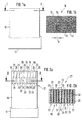
- FIG. 1a a schematic diagram of a burner with a burner body and a combustion chamber in side view
- Figure 1b one Section through the burner body in Figure 1a along the line I-I
- Figure 2a the burner according to Figure 1a with an additional attached gas guiding device
- Figure 2b shows a section by the attached gas guiding device in Figure 2a the line II-II
- Figure 3a shows an alternative embodiment 2a
- 3b show a section through the gas guiding device in Figure 3a along the line III-III
- Figure 3c one Section of Figure 3a with inside the burner body trending channels.
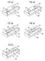
- Figures 4a, 4b, 5a, 5b and 5c show each individual elements of the gas guide device
- figure 6a shows an alternative embodiment of the gas guiding device in top view of the burner body
- FIG. 6b a Section along the line VI-VI in Figure 6a
- Figures 7a to 7c show a further embodiment of a gas guiding device in the form of a one-piece gas baffle
- FIG. 7a shows the gas baffle plate on the burner body side Top view
- Figure 7b shows a first section through Figure 7a along the line VII-VII
- Figure 7c a section through Figure 7a shows along the line VIII-VIII.
- the invention starts out from a recuperator burner, as in a similar form already in the application DE 198 60 460.2 has been described.
- This burner will with regard to the burner body in the form of a ceramic Honeycomb body and with regard to an additional gas guiding device to organize the gas supply to the combustion chamber and modified the exhaust gas removal from the combustion chamber.
- the burner body 10 shown in FIG. 1a and FIG for example in the form of a cuboid monolith, of a multitude of parallel to each other Has channels 12 which in cross section an unordered, especially no regular geometric pattern have subject structure.
- Figure 1b is the greatest width of the channels 12 is drawn and designated b.
- the burner body 10 is a known, ceramic honeycomb body in the form of a cuboid Monoliths with a large number of gas-permeable channels 12, as for example from the production of exhaust gas catalysts is known in motor vehicles. Now around the channels 12 according to FIG.
- a defined function with regard to gas supply and impress exhaust gas discharge in the burner body 10, is shown according to Figure 2, as on that of the combustion chamber 11 facing away from the end face of the burner body 10 is a gas guiding device 21 is set up, at least largely is connected gas-tight to the burner body 10.
- the gas guide device 21 consists of a block of from a large number of immediately adjacent individual elements is composed, each a cuboid Have basic structure.
- the gas guiding device exists in detail 21 according to FIG. 2a from a large number of exhaust gas removal elements 24 and gas supply elements 25, which alternate are arranged periodically one after the other. Any of these Has gas supply elements 25 or exhaust gas discharge elements 24 further, depending on the function, an associated exhaust gas discharge area 22 or associated gas supply area 23 in the form a recess from the exhaust gas discharge element 24 or the gas supply element 25 on.
- the recesses form accordingly their function for gas supply or exhaust gas removal in the figures 2a, 3a, 3c and 6a in the gas supply areas shown in section 23, 27, 26 and exhaust gas discharge areas 22. Further it is provided according to FIG.
- FIG 4a The specific shape of an exhaust gas removal element 24 is shown in FIG 4a clarified once again. From this it can be seen that initially an elongated cuboid with a recess in Shape of the exhaust gas discharge area 22 is provided. Subsequently becomes the exhaust gas discharge element 24 with an open first Bore 41 and a closed second bore 40, with a hole closed under an open hole understand is the gas passage between the borehole and the exhaust gas discharge area 22.
- Figure 4b explains then an analog gas supply element 25 with a Gas supply area 23, in which only the first bore 41 'in the form of a closed bore and the second bore in the form of an open second bore 40 'with gas passage to the gas supply area 23.
- the gas guiding device 21 achieves that the combustion chamber 11 via the second bores 40, 40 ' a fuel-air mixture can be supplied in the combustion chamber 11 ignited and burned there, the in the Combustion chamber 11 resulting exhaust gases then on the principle of Counterflow heat exchanger via the exhaust gas discharge channels 30 can be returned through the burner body 10 while doing so that through the burner body 10 by means of the gas supply channels Preheat the supplied fuel-air mixture before it finally as exhaust gas via the first bores 41, 41 'and the exhaust gas discharge 50 are discharged.
- the Separators 20 of the gas supply elements 25 and the exhaust gas discharge elements 24 each have a width in plan view, which are greater than or equal to the greatest width b of the channels 12 is. It is thereby achieved that the exhaust gas discharge channels 30 and the gas supply channels are at least almost gas-tight from one another are separated and not one channel two different Gases are supplied.
- FIG. 3a to 3c explain in connection with the figures 5a to 5c an alternative exemplary embodiment for implementation of the gas guide device 21.
- FIG. 3b shows that exhaust gas discharge areas 22 periodically with air supply areas 26 and these adjacent fuel supply areas 27 alternate. Otherwise, the structure of the exhaust gas discharge elements 24 or the air supply elements 25 and the fuel supply elements 29 essentially analogous to the first exemplary embodiment.
- the exhaust gas removal element 24 according to FIG. 5a three holes in the form of the second hole 40, a third Bore 42 and the open first bore 41.
- the neighboring Air supply element 28 according to FIG. 5b then has also three holes, namely the first hole 41 ', the opened second bore 40 'and the third bore 42.
- the fuel supply element adjacent to the air supply element 28 29 then also has three holes, namely the first bore 41 ', the second bore 40 and one opened third bore 42 '.
- the opened third hole 42 ' is again gas-permeable with a fuel supply area 27 of the fuel supply element 29 connected in the form of a recess.
- the air supply elements 28 and the fuel supply elements 29 to the gas guiding device 21 in the form of a block and putting it on this block on the end face of the burner body 10 is formed thus a structure according to Figure 3c, the individual Channels 12 in the burner body 10 now through the Gas guiding device 21 imprinted different functions are. So a first part of the channels 12 now serves as exhaust gas Exhaust gas discharge channels 30, a second part as an air duct Air supply channels 31 and a third part as fuel gas Fuel supply channels 32.
- FIG. 3c shows a section of FIG. 3a in the area the gas guiding device 21, in addition the inside of the burner body 10 extending channels 12 in section are shown.
- Figure 3c it can also be seen that guaranteed by the choice of the width of the partition walls 20 is that each channel defines the same function an associated gas is assigned. 3c also shown that by choosing the width of the partitions 20 quite occasionally also closed channels 34 can occur, but the function of the burner does not impaired.
- the specific shape of the gas guiding device 21 in a simple manner to the respective requirements of the burner or the shape of the burner body 10 adjustable. So can the burner body 10 both cylindrical and cuboid be trained. In addition, the shape of the burner body can also 10 adapted to the shape of the gas guiding device 21 his.
- annular one or semicircular basic structure with corresponding have annular or semicircular recesses, so that a periodic sequence of slit-shaped, line-shaped, ring-shaped or semicircular Gas supply areas 23, 26, 27 and exhaust gas removal areas 22 arises.
- channels 12, 30, 31, 32, 34 run parallel within the burner body 10, immediately neighboring and at least largely through thin walls are separated from each other in a gastight manner.
- the typical size of a channel 12 is in cross section 1x1 mm to 2x2 mm.
- the typical size of the torch body 10 is approx. 15 x 15 cm with a height of approx. 30 cm.
- As a material for the burner body 10 in the form of a ceramic Honeycomb body is particularly suitable for aluminum oxide. Besides come other, temperature stable and chemically non-reactive ceramic materials or thermally resistant metals in question. For further details known per se such a recuperative burner is on the application DE 198 60 460.2 referenced.
- FIGS 6a and 6b and 7a to 7c explain two more Exemplary embodiments for realizing a gas guiding device 21, which is placed on the burner body 10.
- FIG. 6a shows a gas guiding device 21 in detail in top view of the burner body, the gas guide device 21 a gas guide plate 47, a gas supply part 46 and has an exhaust gas discharge part 45 arranged opposite this.
- FIG. 6b shows a section along FIG. 6a the drawn cutting line.
- the gas guide plate 47 has line-shaped recesses, which alternately the exhaust gas discharge areas 22 and the Form gas supply areas 23, and through the separating webs 20th are separated from each other.
- the gas guide plate 47 is for this for example in the form of a metallic plate, which is provided with line-shaped millings.
- the gas supply part 46 which is attached to the side of the gas guide plate 47 is and is connected to the gas supply 51, provides for the gas supply areas 23 to have a fuel-air mixture can be supplied, which is then defined by the Gas supply channels in the burner body 10 to the combustion chamber 11 passed, burned there and finally through the Exhaust gas discharge channels 30 reach the exhaust gas discharge areas 22, which in turn are connected to the exhaust gas discharge part 45 are connected to the exhaust gas discharge 50.
- the gas guide device 21 is characterized by the in the explained way executed gas guide plate 47 the channels 12 their function with regard to gas supply and exhaust gas discharge.
- FIG. 7a shows the gas guiding device 21 in the form of a one-piece gas guide plate 48, which with concentric, annular or slot-shaped recesses is provided, the alternating gas supply areas 23 and exhaust gas removal areas 22 form, which are separated from one another by separating webs 20 are.
- the width of the dividers 20 is again at least equal to or greater than the largest width b of the channels 12 in the fuel body 10.
- the gas baffle 48 on two from its center outgoing rays arranged on a line has web-shaped separators 55, 56, each of which slot-shaped or annular recesses in the gas guide disk 48 interrupt.
- the height of the separators 55, 56 corresponds to the depth of the recesses.
- separators 55, 56 when interrupting the Recesses alternately a first and a larger second Have width.
- gas baffle 48 two opposite holes 53, 54, with a first through hole 53 along the first, from the center of the gas baffle 48 outgoing beam through the separators 55, 56, and second bore 54 along the second beam through the Separators 55, 56 runs.
- the first and second through holes 53, 54 have preferred continue to have the same diameter, which is dimensioned that it is larger than the first and smaller than the second Width of the separators 55, 56 is. In this way it is achieved that the narrower separators 55 through the through hole open laterally while the wider ones Separators 56 only pierced, but not opened become.
- FIG. 7 a shows that the first through hole 53 with the exhaust gas discharge 50 and the second bore 54 with the gas supply 51 is connected so that overall from the exhaust gas discharge areas 22 via the first perforation 53 the exhaust gas can be removed in a defined manner, while by means of the second through hole 54 in a defined manner A fuel-air mixture can be supplied to gas supply areas 23 is.
- FIG. 7c shows that in addition to the separating webs 20, a closed separator 56 with one located therein Drill hole 52 is visible from the second through hole 54. It is further shown in FIG. 7c that the recesses in the gas guiding device 21 in this case exhaust gas discharge areas 22 are.
Landscapes
- Engineering & Computer Science (AREA)
- Chemical & Material Sciences (AREA)
- Combustion & Propulsion (AREA)
- Mechanical Engineering (AREA)
- General Engineering & Computer Science (AREA)
- Combustion Of Fluid Fuel (AREA)
Applications Claiming Priority (2)
| Application Number | Priority Date | Filing Date | Title |
|---|---|---|---|
| DE10042761 | 2000-06-20 | ||
| DE10042761A DE10042761C1 (de) | 2000-06-20 | 2000-06-20 | Rekuperativer Brenner mit Gasleitvorrichtung |
Publications (1)
| Publication Number | Publication Date |
|---|---|
| EP1167879A1 true EP1167879A1 (fr) | 2002-01-02 |
Family
ID=7654413
Family Applications (1)
| Application Number | Title | Priority Date | Filing Date |
|---|---|---|---|
| EP01114198A Withdrawn EP1167879A1 (fr) | 2000-06-20 | 2001-06-12 | Brûleur à récupération avec unité de distribution de gaz |
Country Status (2)
| Country | Link |
|---|---|
| EP (1) | EP1167879A1 (fr) |
| DE (1) | DE10042761C1 (fr) |
Citations (4)
| Publication number | Priority date | Publication date | Assignee | Title |
|---|---|---|---|---|
| US4435153A (en) * | 1980-07-21 | 1984-03-06 | Hitachi, Ltd. | Low Btu gas burner |
| JPS60114616A (ja) * | 1983-11-24 | 1985-06-21 | Kawasaki Heavy Ind Ltd | セラミックハニカム燃焼器 |
| DE19740625A1 (de) * | 1997-09-16 | 1999-03-18 | Ruhrgas Ag | Flächenbrenner |
| DE19860460A1 (de) * | 1998-12-28 | 2000-06-29 | Bosch Gmbh Robert | Integrierter rekuperativer Brenner |
Family Cites Families (5)
| Publication number | Priority date | Publication date | Assignee | Title |
|---|---|---|---|---|
| DE2853309C2 (de) * | 1978-12-09 | 1984-04-05 | Kernforschungsanlage Jülich GmbH, 5170 Jülich | Keramischer Brennerkopf für gasförmigen Brennstoff |
| DE3014059C2 (de) * | 1980-04-11 | 1985-12-19 | Hoechst CeramTec AG, 8672 Selb | Keramischer Brennerkopf mit zum Brennermund parallel zueinander geführten, schlitzförmigen Strömungskanälen für Brennstoff und Oxidationsmittel |
| US4707560A (en) * | 1986-12-19 | 1987-11-17 | Tpv Energy Systems, Inc. | Thermophotovoltaic technology |
| EP0324043B1 (fr) * | 1988-01-15 | 1991-09-04 | WS Wärmeprozesstechnik GmbH | Brûleur industriel avec préchauffage de l'air, en particulier pour chauffer les chambres des fours industriels |
| WO1995015462A1 (fr) * | 1993-12-03 | 1995-06-08 | Nippon Furnace Kogyo Kabushiki Kaisha | Bruleur du type a regeneration et systeme echangeur de chaleur associe du type a emmagasinage |
-
2000
- 2000-06-20 DE DE10042761A patent/DE10042761C1/de not_active Expired - Fee Related
-
2001
- 2001-06-12 EP EP01114198A patent/EP1167879A1/fr not_active Withdrawn
Patent Citations (4)
| Publication number | Priority date | Publication date | Assignee | Title |
|---|---|---|---|---|
| US4435153A (en) * | 1980-07-21 | 1984-03-06 | Hitachi, Ltd. | Low Btu gas burner |
| JPS60114616A (ja) * | 1983-11-24 | 1985-06-21 | Kawasaki Heavy Ind Ltd | セラミックハニカム燃焼器 |
| DE19740625A1 (de) * | 1997-09-16 | 1999-03-18 | Ruhrgas Ag | Flächenbrenner |
| DE19860460A1 (de) * | 1998-12-28 | 2000-06-29 | Bosch Gmbh Robert | Integrierter rekuperativer Brenner |
Non-Patent Citations (1)
| Title |
|---|
| PATENT ABSTRACTS OF JAPAN vol. 009, no. 268 (M - 424) 25 October 1985 (1985-10-25) * |
Also Published As
| Publication number | Publication date |
|---|---|
| DE10042761C1 (de) | 2001-09-13 |
Similar Documents
| Publication | Publication Date | Title |
|---|---|---|
| EP0324043B1 (fr) | Brûleur industriel avec préchauffage de l'air, en particulier pour chauffer les chambres des fours industriels | |
| DE19502796B4 (de) | Brenner | |
| DE3923046A1 (de) | Ringtabletten fuer gasgeneratoren | |
| DE2733640B2 (de) | Matrix für einen katalytischen Reaktor zur Abgasreinigung bei Brennkraftmaschinen | |
| WO2009094791A2 (fr) | Brûleur à gaz | |
| EP4423842B1 (fr) | Chambre de décharge de gaz et ensemble batterie pour décharger des gaz à partir d'une batterie de véhicule automobile | |
| DE2708630A1 (de) | Brenner | |
| EP0093472B1 (fr) | Brique creuse prismatique en matériaux réfractaires pour l'empilage des chambres d'un four de verrerie | |
| DE3910554A1 (de) | Unter verwendung einseitig verschlossener gelochter rohre aufgebautes partikelfilter | |
| EP0543324A2 (fr) | Brûleur pour fours industriels | |
| EP0543323A2 (fr) | Brûleur pour fours industriels | |
| DE19860460C2 (de) | Integrierter rekuperativer Brenner | |
| EP0483743A2 (fr) | Brique réfractaire en fibre et brûleur avec une telle brique réfractaire en fibre | |
| DE10042761C1 (de) | Rekuperativer Brenner mit Gasleitvorrichtung | |
| DE10237604B4 (de) | Nachverbrennungseinrichtung mit einem Brenner | |
| DE2034352A1 (de) | Brenner | |
| DE10038095C2 (de) | Anordnung zur Flammenüberwachung von Poren- und Gestrickbrennern | |
| DE1476618C3 (de) | Nach verbrennungsvorrichtung für die Auspuffgase von Brennkraftmaschinen | |
| DE2832442C2 (de) | Wärmeofen | |
| DE1551771C3 (de) | Verbrennungseinrichtung mit einer Brennkammer zur inneren Verbrennung eines Brenngas-Luft-Gemisches | |
| AT399029B (de) | Brenneranordnung | |
| DE2912518C2 (fr) | ||
| DE68924539T2 (de) | Verbrennungsvorrichtung. | |
| EP0017156A2 (fr) | Tête de brûleur céramique avec canaux pour combustible et pour agent oxydant guidés parallèlement à la buse du brûleur | |
| AT412531B (de) | Wabenkörpereinrichtung für die thermische abgasbehandlung |
Legal Events
| Date | Code | Title | Description |
|---|---|---|---|
| PUAI | Public reference made under article 153(3) epc to a published international application that has entered the european phase |
Free format text: ORIGINAL CODE: 0009012 |
|
| AK | Designated contracting states |
Kind code of ref document: A1 Designated state(s): FR GB IT NL Kind code of ref document: A1 Designated state(s): AT BE CH CY DE DK ES FI FR GB GR IE IT LI LU MC NL PT SE TR |
|
| AX | Request for extension of the european patent |
Free format text: AL;LT;LV;MK;RO;SI |
|
| 17P | Request for examination filed |
Effective date: 20020702 |
|
| AKX | Designation fees paid |
Free format text: FR GB IT NL |
|
| REG | Reference to a national code |
Ref country code: DE Ref legal event code: 8566 |
|
| 17Q | First examination report despatched |
Effective date: 20040129 |
|
| GRAP | Despatch of communication of intention to grant a patent |
Free format text: ORIGINAL CODE: EPIDOSNIGR1 |
|
| STAA | Information on the status of an ep patent application or granted ep patent |
Free format text: STATUS: THE APPLICATION IS DEEMED TO BE WITHDRAWN |
|
| 18D | Application deemed to be withdrawn |
Effective date: 20050118 |