EP1167892A2 - Solar-Wärmespeicher - Google Patents
Solar-Wärmespeicher Download PDFInfo
- Publication number
- EP1167892A2 EP1167892A2 EP01114185A EP01114185A EP1167892A2 EP 1167892 A2 EP1167892 A2 EP 1167892A2 EP 01114185 A EP01114185 A EP 01114185A EP 01114185 A EP01114185 A EP 01114185A EP 1167892 A2 EP1167892 A2 EP 1167892A2
- Authority
- EP
- European Patent Office
- Prior art keywords
- solar
- thermoaccumulator
- reservoir
- fluid
- heated
- Prior art date
- Legal status (The legal status is an assumption and is not a legal conclusion. Google has not performed a legal analysis and makes no representation as to the accuracy of the status listed.)
- Withdrawn
Links
Images

Classifications
-
- F—MECHANICAL ENGINEERING; LIGHTING; HEATING; WEAPONS; BLASTING
- F24—HEATING; RANGES; VENTILATING
- F24S—SOLAR HEAT COLLECTORS; SOLAR HEAT SYSTEMS
- F24S10/00—Solar heat collectors using working fluids
- F24S10/90—Solar heat collectors using working fluids using internal thermosiphonic circulation
- F24S10/95—Solar heat collectors using working fluids using internal thermosiphonic circulation having evaporator sections and condenser sections, e.g. heat pipes
-
- F—MECHANICAL ENGINEERING; LIGHTING; HEATING; WEAPONS; BLASTING
- F24—HEATING; RANGES; VENTILATING
- F24S—SOLAR HEAT COLLECTORS; SOLAR HEAT SYSTEMS
- F24S60/00—Arrangements for storing heat collected by solar heat collectors
- F24S60/30—Arrangements for storing heat collected by solar heat collectors storing heat in liquids
-
- Y—GENERAL TAGGING OF NEW TECHNOLOGICAL DEVELOPMENTS; GENERAL TAGGING OF CROSS-SECTIONAL TECHNOLOGIES SPANNING OVER SEVERAL SECTIONS OF THE IPC; TECHNICAL SUBJECTS COVERED BY FORMER USPC CROSS-REFERENCE ART COLLECTIONS [XRACs] AND DIGESTS
- Y02—TECHNOLOGIES OR APPLICATIONS FOR MITIGATION OR ADAPTATION AGAINST CLIMATE CHANGE
- Y02B—CLIMATE CHANGE MITIGATION TECHNOLOGIES RELATED TO BUILDINGS, e.g. HOUSING, HOUSE APPLIANCES OR RELATED END-USER APPLICATIONS
- Y02B10/00—Integration of renewable energy sources in buildings
- Y02B10/20—Solar thermal
-
- Y—GENERAL TAGGING OF NEW TECHNOLOGICAL DEVELOPMENTS; GENERAL TAGGING OF CROSS-SECTIONAL TECHNOLOGIES SPANNING OVER SEVERAL SECTIONS OF THE IPC; TECHNICAL SUBJECTS COVERED BY FORMER USPC CROSS-REFERENCE ART COLLECTIONS [XRACs] AND DIGESTS
- Y02—TECHNOLOGIES OR APPLICATIONS FOR MITIGATION OR ADAPTATION AGAINST CLIMATE CHANGE
- Y02E—REDUCTION OF GREENHOUSE GAS [GHG] EMISSIONS, RELATED TO ENERGY GENERATION, TRANSMISSION OR DISTRIBUTION
- Y02E10/00—Energy generation through renewable energy sources
- Y02E10/40—Solar thermal energy, e.g. solar towers
- Y02E10/44—Heat exchange systems
Definitions
- the present invention relates to a solar thermoaccumulator.
- the present invention relates to a solar thermoaccumulator of the type comprising a battery of closed-circuit vacuum heat pipes that transfer heat to a circuit to be heated.
- solar panels designed for heating water in houses or community facilities such as: hotels, gymnasiums, barracks, camping grounds, and so on.
- Said panels are substantially designed as function of the process that exploits the physical law according to which hot fluids naturally travel from down upwards, while the cold ones travel in the contrary direction.
- Some types of flat plate collectors or solar panels are constituted of flat, blackened, metal containers in whose inside the primary fluid flows in coiling pipes. They are insulated at the bottom to prevent convection heat losses, comprise top blackened glass panels, and are so oriented as to ensure the perpendicularity of their surface with respect to the average direction of sun rays.
- Said solar pipes comprise an absorbing plate bonded to a heat pipe, and the assembly is sealed within an evacuated glass pipe; the heat pipe is coupled to a condenser. The radiation striking the plate is absorbed and then transferred as thermal energy to the condenser.
- the absorbing plate is coated with a special high efficiency selective coating which ensures the maximum radiation absorption and minimum thermal radiation losses. Heat, which cannot scatter thanks to the internal vacuum condition, is transmitted without appreciable scattering to an adjoining tubular body provided with an intermediate wall that separates the delivery circuit from the return circuit of the primary fluid.
- the heated primary fluid can be exploited in a different way.
- the upper part of each solar pipe comprises hydraulic taps through which the heated fluid is connected to a heat exchanger that heats the water contained in an accumulation reservoir connected to the distribution systems.
- the upper accumulation bulbs of the solar pipes are, instead, adheringly engaged, with heat transmission by convection and conduction, in corresponding profiled niches, obtained on the same piping of the circuit of the heat exchanger.
- Object of the present, invention is to eliminate the above drawbacks.
- object of the present invention is to provide a solar thermoaccumulator which, besides having high thermal yields and efficacy, is easily realizable and has a very reduced cost.
- a solar thermoaccumulator comprising a battery of closed-circuit vacuum solar pipe, each pipe being coupled to a heat accumulation bulb or condenser; a reservoir containing a fluid to be heated, circumscribed by a shell and provided with fluid feeding pipes and discharge pipes, and a means for transferring heat from said heat accumulation bulbs to the fluid to be heated, wherein the heat accumulation bulbs or condensers are mounted on the lower surface of the shell of the reservoir containing the fluid to be heated.
- the reservoir containing the fluid to be heated is provided with a peripheral, annular, enveloping chamber having an air space, whereto the primary conductive liquid is caused to flow, and the heat accumulation bulbs or condensers are immersed in said primary conductive liquid.
- the lower surface of the reservoir containing the fluid to be heated is provided with tubular, parallel and aligned tangs, and the heat accumulating bulbs or condenser are placed in direct thermal conduction touch with said tangs.
- the reservoir containing the fluid to be heated may be a single one, having preferably a horizontal development, or it may be associated to other reservoirs, horizontal, parallel aligned and communicating with each other through slits or longitudinal ports.
- the advantages achieved by the solar thermoaccumulator of the present invention lie essentially in that the connections of the accumulation bulbs of the closed-circuit vacuum solar pipes with the reservoirs are much simpler to construct and more accessible for both the assembly and maintenance operations, and besides the mutual association of heat transfer is caused to be more effective, with a higher yield.
- Another advantage lies in that, as the minimum overall dimensions increase, marked increases in the heated fluid capacity are obtained.
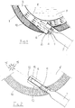
- Figure 1 relates to a first example of embodiment of a fluid indirect heating thermoaccumulator.
- a reservoir containing the fluid to be heated having preferably a horizontally developed cylindrical shape, comprises a plurality of lower unions 2.
- Said unions 2 are equidistant throughout the longitudinal lower extension of said container 9, with an alignment substantially tangential to an annular peripheral chamber 3 containing a conductive primary fluid.
- Said annular chamber 3 is circumscribed by an external wall 1 and an internal wall 8 in touch with the fluid to be heated.
- Said condensers 6 are immersed in and get in a direct contact relation with said conductive fluid that circulates in said annular chamber 3, such as for instance water or other suitable conductive liquids.
- Said fluid is comprised in chamber 3, recirculates as closed-circuit in the same, heats when it gets in touch with bulbs 6, goes upwards with a natural motion along the peripheral chamber 3, transfers progressively its heat to the internal part 8 of reservoir 9, goes downwards once cooled, along the opposite side of said chamber 3 and gets anew in touch with bulbs 6, to heat again.
- the heat which the fluid transfers to the internal walls 8 is transferred by the latter to the water to be heated contained in reservoir 9.
- the external wall 1 of chamber 3 is adequately covered with an insulating material 10, to reduce as much as possible heat losses towards the outside and to convey all the thermal exchange of the primary fluid towards the internal wall 8.
- the closed-circuit vacuum solar pipes 7 are oriented and inclined to obtain a position substantially perpendicular to the average direction of sun rays.
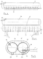
- FIG. 2 relates to a second example of the water direct heating thermoaccumulator of the present invention.
- reservoir 9' having preferably but not critically a horizontal development cylindrical shape, comprises a plurality of internal tangs 11, which are equidistant throughout the longitudinal lower extension of reservoir 9'. Tangs 11 are open towards the outside, while their end 12, included in the reservoir, is sealed.
- bulbs 6 and tangs 11 are realized from different materials having a different expansion coefficient.
- bulbs are made from copper and tangs from steel, as copper has a linear expansion coefficient higher by about 50% than that of steel. This allows to realize both components with dimensions sufficient to ensure their cold coupling with a clearance, while once heated, the same clearance is entirely annulled by the different linear expansion of the materials, with ensuring perfect adhesion between the parts.
- the same tangs 11, may be realized, depending on the characteristics of the thermoaccumulators, with the surfaces in touch with the fluid to be heated that can be smooth 13, or have parallel annular finnings 14, or radial finnings 15.
- This allows to increase the capacity of hot water accumulation of reservoir 9 or 9', keeping in any case the overall external size of the corresponding thermoaccumulator within reasonable limits to restrain the non harmonic effects it causes, especially when it is located on house roofs, without increasing its diameter.
- connection between the main reservoir 9 or 9' and the auxiliary reservoir(s) 16 takes place through the longitudinal slits 17 created in the zone of sealing coupling. Also in the auxiliary reservoirs, the water heated by the direct or indirect heat sources goes upwards, while cold air goes downwards.
- thermoaccumulators may be provided with electric resistances for the possible heat integration in case of long period of bad whether.
Landscapes
- Engineering & Computer Science (AREA)
- Chemical & Material Sciences (AREA)
- Life Sciences & Earth Sciences (AREA)
- Sustainable Development (AREA)
- Sustainable Energy (AREA)
- Thermal Sciences (AREA)
- Physics & Mathematics (AREA)
- Combustion & Propulsion (AREA)
- Mechanical Engineering (AREA)
- General Engineering & Computer Science (AREA)
- Photovoltaic Devices (AREA)
- Road Signs Or Road Markings (AREA)
- Heat-Pump Type And Storage Water Heaters (AREA)
Applications Claiming Priority (2)
| Application Number | Priority Date | Filing Date | Title |
|---|---|---|---|
| IT2000CO000016A ITCO20000016A1 (it) | 2000-06-22 | 2000-06-22 | Termoaccumulatore solare. |
| ITCO000016 | 2000-06-22 |
Publications (2)
| Publication Number | Publication Date |
|---|---|
| EP1167892A2 true EP1167892A2 (de) | 2002-01-02 |
| EP1167892A3 EP1167892A3 (de) | 2004-01-21 |
Family
ID=11441214
Family Applications (1)
| Application Number | Title | Priority Date | Filing Date |
|---|---|---|---|
| EP01114185A Withdrawn EP1167892A3 (de) | 2000-06-22 | 2001-06-12 | Solar-Wärmespeicher |
Country Status (4)
| Country | Link |
|---|---|
| US (1) | US6655375B2 (de) |
| EP (1) | EP1167892A3 (de) |
| JP (1) | JP2002031414A (de) |
| IT (1) | ITCO20000016A1 (de) |
Cited By (5)
| Publication number | Priority date | Publication date | Assignee | Title |
|---|---|---|---|---|
| DE10351633A1 (de) * | 2003-11-05 | 2005-06-16 | Ritter Solar Gmbh & Co.Kg | Anlage zum Erhitzen einer Flüssigkeit mittels Solarenergie |
| FR2865797A1 (fr) * | 2004-02-02 | 2005-08-05 | Jean Paul Carraz | Dispositif permettant d'eviter un surpresseur electrique, lors de l'utilisation sur le reseau d'eau, d'un chauffe-eau solaire avec capteurs tubulaires sous vide |
| BE1016509A3 (fr) * | 2005-04-27 | 2006-12-05 | Sprl Joseph Zurstrassen | Concentrateur-transporteur fractionne d'energie via fluide caloporteur a changement de phases nouveau dispositif. |
| DE102007043964A1 (de) * | 2007-09-14 | 2009-04-02 | Greenonetec Solarindustrie Gmbh | Solarkollektor mit angeschlossenem Behälter zur Speicherung von Warmwasser |
| RU171104U1 (ru) * | 2016-09-13 | 2017-05-22 | Алексей Николаевич Жаринов | Трубка солнечного коллектора |
Families Citing this family (12)
| Publication number | Priority date | Publication date | Assignee | Title |
|---|---|---|---|---|
| US20080047544A1 (en) * | 2006-07-24 | 2008-02-28 | Chong Han | Modular thermal radiation heating system |
| IL192499A (en) * | 2008-06-29 | 2013-03-24 | S E S Solar Energy Solutions Ltd | Solar collector |
| EP2504636A4 (de) | 2009-11-23 | 2014-12-17 | Siang Teik Teoh | Solarerhitzer mit koaxialröhren und nächtlicher kühlung |
| IT1399310B1 (it) * | 2010-03-23 | 2013-04-16 | Riello Spa | Sistema ad energia solare per il riscaldamento di acqua sanitaria |
| US8375934B2 (en) * | 2010-04-26 | 2013-02-19 | Shanghai Jite Enterprise Co., Ltd. | Solar water heater retrofitted from conventional water heater, system and method |
| EP2780642B1 (de) * | 2011-11-11 | 2016-06-08 | CMG Solari S.r.l. | Solaranlage mit natürlicher zirkulation und vakuumröhren mit einem sammeltank-hohlraum |
| KR101281074B1 (ko) * | 2012-11-14 | 2013-07-02 | 전영춘 | 태양에너지를 이용한 발전 및 난방 시스템 |
| US9400121B2 (en) * | 2013-10-09 | 2016-07-26 | Ali A. Fakih | Solar thermal lamps and globes for heating water in a water tank |
| CN104214963B (zh) * | 2013-12-31 | 2016-04-20 | 冯卓林 | 太阳空气能真空保温储水循环聚热器 |
| US9664411B2 (en) * | 2014-08-26 | 2017-05-30 | Haier Us Appliance Solutions, Inc. | Water heater appliance with an angled anode |
| DE102017107458A1 (de) * | 2017-04-06 | 2018-10-11 | Enertracting Gmbh | Solarkollektor-Sammelrohr, Verwendung von Solarkollektor-Sammelrohren und Solarkollektor-Baugruppe |
| US12369278B1 (en) * | 2022-02-24 | 2025-07-22 | Advanced Cooling Technologies, Inc. | Multi-condenser variable conductance heat pipe |
Family Cites Families (16)
| Publication number | Priority date | Publication date | Assignee | Title |
|---|---|---|---|---|
| US4056093A (en) * | 1975-12-05 | 1977-11-01 | Barger Harold E | Solar heater |
| DE2734521A1 (de) * | 1977-07-30 | 1979-02-15 | Weller Konrad Prof Dr Ing | Sonnenenergieanlage |
| IT7922198U1 (it) * | 1979-07-25 | 1981-01-25 | I Ge Co Pontello Prefabbricati S P A | Elemento di parete prefabbricato ad elevata coibenza termoacustica. |
| NZ194763A (en) * | 1979-09-07 | 1984-05-31 | Solarcore Ind Pty Ltd | Solar energy storage collector and refelctor: end manifolds connected by cylindrically arranged tubes |
| JPS5642058A (en) * | 1979-09-13 | 1981-04-20 | Kubota Ltd | Solar energy water heater |
| US4299203A (en) * | 1979-11-13 | 1981-11-10 | Exxon Research & Engineering Co. | Tubular solar collector system |
| US4513732A (en) * | 1981-11-10 | 1985-04-30 | Feldman Jr Karl T | Passive integral solar heat collector system |
| DE3236882A1 (de) * | 1982-10-05 | 1984-04-05 | Vama Vertrieb Von Anlagen Und Maschinen Gmbh & Co Kg, 3200 Hildesheim | Solaranlage mit waermerohr-kollektoren |
| GB2131155B (en) * | 1982-11-26 | 1987-03-11 | Sabet Faramarz Mahdjuri | Solar heating |
| JPS6048054U (ja) * | 1983-09-08 | 1985-04-04 | 白木金属工業株式会社 | 自然循環型太陽熱集熱器 |
| US4505261A (en) * | 1983-12-19 | 1985-03-19 | Hunter Billy D | Modular passive solar heating system |
| US4686961A (en) * | 1985-11-01 | 1987-08-18 | John D. Garrison | Integrated solar thermal energy collector system |
| JPH03164668A (ja) * | 1989-11-24 | 1991-07-16 | Mitsubishi Electric Corp | ヒートポンプ装置 |
| GB9011261D0 (en) * | 1990-05-19 | 1990-07-11 | Mahdjuri Sabet Faramarz | Heat-pipe-device |
| JP3164668B2 (ja) | 1992-09-28 | 2001-05-08 | 出光興産株式会社 | 粒状ポリカーボネートの製造方法 |
| US6370328B1 (en) * | 1997-10-08 | 2002-04-09 | Bernard J. Mottershead | Water heating tank with thermosiphonic circulation for improved heat recovery rate |
-
2000
- 2000-06-22 IT IT2000CO000016A patent/ITCO20000016A1/it unknown
-
2001
- 2001-06-12 EP EP01114185A patent/EP1167892A3/de not_active Withdrawn
- 2001-06-19 JP JP2001184322A patent/JP2002031414A/ja active Pending
- 2001-06-20 US US09/885,402 patent/US6655375B2/en not_active Expired - Fee Related
Cited By (6)
| Publication number | Priority date | Publication date | Assignee | Title |
|---|---|---|---|---|
| DE10351633A1 (de) * | 2003-11-05 | 2005-06-16 | Ritter Solar Gmbh & Co.Kg | Anlage zum Erhitzen einer Flüssigkeit mittels Solarenergie |
| FR2865797A1 (fr) * | 2004-02-02 | 2005-08-05 | Jean Paul Carraz | Dispositif permettant d'eviter un surpresseur electrique, lors de l'utilisation sur le reseau d'eau, d'un chauffe-eau solaire avec capteurs tubulaires sous vide |
| BE1016509A3 (fr) * | 2005-04-27 | 2006-12-05 | Sprl Joseph Zurstrassen | Concentrateur-transporteur fractionne d'energie via fluide caloporteur a changement de phases nouveau dispositif. |
| DE102007043964A1 (de) * | 2007-09-14 | 2009-04-02 | Greenonetec Solarindustrie Gmbh | Solarkollektor mit angeschlossenem Behälter zur Speicherung von Warmwasser |
| DE102007043964B4 (de) * | 2007-09-14 | 2009-08-27 | Greenonetec Solarindustrie Gmbh | Solarkollektor mit angeschlossenem Behälter zur Speicherung von Warmwasser |
| RU171104U1 (ru) * | 2016-09-13 | 2017-05-22 | Алексей Николаевич Жаринов | Трубка солнечного коллектора |
Also Published As
| Publication number | Publication date |
|---|---|
| ITCO20000016A1 (it) | 2001-12-22 |
| US20010054419A1 (en) | 2001-12-27 |
| US6655375B2 (en) | 2003-12-02 |
| EP1167892A3 (de) | 2004-01-21 |
| JP2002031414A (ja) | 2002-01-31 |
Similar Documents
| Publication | Publication Date | Title |
|---|---|---|
| EP1167892A2 (de) | Solar-Wärmespeicher | |
| US4237866A (en) | Solar heater | |
| EP0852689B1 (de) | Solar-wasserheizungssystem mit heizröhren und integriertem wärmespeicher | |
| US8353286B2 (en) | Solar water heater and method | |
| US7971587B2 (en) | Apparatus and method for solar thermal energy collection | |
| JP2600694Y2 (ja) | 水加熱装置 | |
| CN103954048A (zh) | 一种太阳能集热输送装置 | |
| CN101319821A (zh) | 建筑平板形分体壁挂真空太阳能超导集热装置 | |
| CN110906428B (zh) | 相变储热式太阳能热管加热器 | |
| USH2231H1 (en) | Tubular heating-pipe solar water-heating-system with integral tank | |
| US20090107488A1 (en) | Apparatus and Method for Solar Thermal Energy Collection | |
| AU2010328722B2 (en) | Thermal solar panel with integrated chemical heat pump | |
| GB2081861A (en) | Solar heating system | |
| EP2754977A1 (de) | Sonnenkollektor mit einem gewellten Rohr | |
| US8316842B2 (en) | Solar heat collector | |
| US20090241940A1 (en) | Solar thermal collector manifold | |
| EP0015017A1 (de) | Solarkollektor mit Wärmetransportrohr und System mit mindestens einem derartigen Kollektor | |
| CN101769641A (zh) | 太阳能热水器 | |
| NL194925C (nl) | Zonnecollector. | |
| KR20050090868A (ko) | 복합식 진공관형 태양열 집열기 | |
| CN201081427Y (zh) | 联集管式太阳能集热器 | |
| JPS6337640Y2 (de) | ||
| JPS60105863A (ja) | 太陽熱集熱器 | |
| CN1046032A (zh) | 一种用于太阳能集热的玻璃热管 | |
| AU2012244342A1 (en) | Solar Collector |
Legal Events
| Date | Code | Title | Description |
|---|---|---|---|
| PUAI | Public reference made under article 153(3) epc to a published international application that has entered the european phase |
Free format text: ORIGINAL CODE: 0009012 |
|
| AK | Designated contracting states |
Kind code of ref document: A2 Designated state(s): AT BE CH CY DE DK ES FI FR GB GR IE IT LI LU MC NL PT SE TR |
|
| AX | Request for extension of the european patent |
Free format text: AL;LT;LV;MK;RO;SI |
|
| PUAL | Search report despatched |
Free format text: ORIGINAL CODE: 0009013 |
|
| AK | Designated contracting states |
Kind code of ref document: A3 Designated state(s): AT BE CH CY DE DK ES FI FR GB GR IE IT LI LU MC NL PT SE TR |
|
| AX | Request for extension of the european patent |
Extension state: AL LT LV MK RO SI |
|
| AKX | Designation fees paid |
Designated state(s): AT BE CH CY DE DK ES FI FR GB GR IE IT LI LU MC NL PT SE TR |
|
| STAA | Information on the status of an ep patent application or granted ep patent |
Free format text: STATUS: THE APPLICATION IS DEEMED TO BE WITHDRAWN |
|
| 18D | Application deemed to be withdrawn |
Effective date: 20040722 |