EP1168017A2 - Connecteur à fibres optiques - Google Patents
Connecteur à fibres optiques Download PDFInfo
- Publication number
- EP1168017A2 EP1168017A2 EP01114648A EP01114648A EP1168017A2 EP 1168017 A2 EP1168017 A2 EP 1168017A2 EP 01114648 A EP01114648 A EP 01114648A EP 01114648 A EP01114648 A EP 01114648A EP 1168017 A2 EP1168017 A2 EP 1168017A2
- Authority
- EP
- European Patent Office
- Prior art keywords
- connector
- fanout
- housing
- mounting
- cable
- Prior art date
- Legal status (The legal status is an assumption and is not a legal conclusion. Google has not performed a legal analysis and makes no representation as to the accuracy of the status listed.)
- Ceased
Links
Images


Classifications
-
- G—PHYSICS
- G02—OPTICS
- G02B—OPTICAL ELEMENTS, SYSTEMS OR APPARATUS
- G02B6/00—Light guides; Structural details of arrangements comprising light guides and other optical elements, e.g. couplings
- G02B6/24—Coupling light guides
- G02B6/36—Mechanical coupling means
-
- G—PHYSICS
- G02—OPTICS
- G02B—OPTICAL ELEMENTS, SYSTEMS OR APPARATUS
- G02B6/00—Light guides; Structural details of arrangements comprising light guides and other optical elements, e.g. couplings
- G02B6/24—Coupling light guides
- G02B6/36—Mechanical coupling means
- G02B6/38—Mechanical coupling means having fibre to fibre mating means
- G02B6/3807—Dismountable connectors, i.e. comprising plugs
- G02B6/3873—Connectors using guide surfaces for aligning ferrule ends, e.g. tubes, sleeves, V-grooves, rods, pins, balls
- G02B6/3874—Connectors using guide surfaces for aligning ferrule ends, e.g. tubes, sleeves, V-grooves, rods, pins, balls using tubes, sleeves to align ferrules
- G02B6/3878—Connectors using guide surfaces for aligning ferrule ends, e.g. tubes, sleeves, V-grooves, rods, pins, balls using tubes, sleeves to align ferrules comprising a plurality of ferrules, branching and break-out means
-
- G—PHYSICS
- G02—OPTICS
- G02B—OPTICAL ELEMENTS, SYSTEMS OR APPARATUS
- G02B6/00—Light guides; Structural details of arrangements comprising light guides and other optical elements, e.g. couplings
- G02B6/24—Coupling light guides
- G02B6/36—Mechanical coupling means
- G02B6/38—Mechanical coupling means having fibre to fibre mating means
- G02B6/3807—Dismountable connectors, i.e. comprising plugs
- G02B6/3887—Anchoring optical cables to connector housings, e.g. strain relief features
-
- G—PHYSICS
- G02—OPTICS
- G02B—OPTICAL ELEMENTS, SYSTEMS OR APPARATUS
- G02B6/00—Light guides; Structural details of arrangements comprising light guides and other optical elements, e.g. couplings
- G02B6/44—Mechanical structures for providing tensile strength and external protection for fibres, e.g. optical transmission cables
- G02B6/4439—Auxiliary devices
- G02B6/4471—Terminating devices ; Cable clamps
- G02B6/44715—Fan-out devices
-
- G—PHYSICS
- G02—OPTICS
- G02B—OPTICAL ELEMENTS, SYSTEMS OR APPARATUS
- G02B6/00—Light guides; Structural details of arrangements comprising light guides and other optical elements, e.g. couplings
- G02B6/24—Coupling light guides
- G02B6/36—Mechanical coupling means
- G02B6/3628—Mechanical coupling means for mounting fibres to supporting carriers
- G02B6/368—Mechanical coupling means for mounting fibres to supporting carriers with pitch conversion between input and output plane, e.g. for increasing packing density
-
- G—PHYSICS
- G02—OPTICS
- G02B—OPTICAL ELEMENTS, SYSTEMS OR APPARATUS
- G02B6/00—Light guides; Structural details of arrangements comprising light guides and other optical elements, e.g. couplings
- G02B6/24—Coupling light guides
- G02B6/36—Mechanical coupling means
- G02B6/38—Mechanical coupling means having fibre to fibre mating means
- G02B6/3807—Dismountable connectors, i.e. comprising plugs
- G02B6/3873—Connectors using guide surfaces for aligning ferrule ends, e.g. tubes, sleeves, V-grooves, rods, pins, balls
- G02B6/3885—Multicore or multichannel optical connectors, i.e. one single ferrule containing more than one fibre, e.g. ribbon type
Definitions
- This invention generally relates to the art of connector assemblies and, particularly, to a fiber optic connector assembly, but certain features of the invention may be equally applicable for use with other types of connectors such as electrical connectors.
- Fiber optic connectors of a wide variety of designs have been employed to terminate optical fiber cables and to facilitate connection of the cables to other cables or other optical fiber transmission devices.
- a typical fiber optic connector includes a ferrule which mounts and centers an optical fiber or fibers within the connector. The ferrule may be fabricated of such material as ceramics.
- a multi-fiber optic cable is terminated in the connector, and a plurality of individual optical fibers of the cable may be terminated in the ferrule.
- a popular type of fiber optic cable is a multi-fiber flat cable which conventionally is called a ribbon cable.
- a fanout connector typically is used with a ribbon-type cable.
- the individual optical fibers of the cable are very closely spaced.
- a fanout connector includes a fanout means such as a fanout insert for receiving and spreading the individual fibers of the cable transversely thereof so that the fibers are more easily connectorized according to hardware interface requirements.
- the individual fibers extend away from the fanout insert within a plurality of easily manipulatable tubes which also protect the fibers.
- the tubes often are color-coded.
- the present invention is directed to providing various improvements in connector assemblies, such as fiber optic connector assemblies, including fanout-type fiber optic connectors.
- An object, therefore, of the invention is to provide a new and improved connector assembly, such as a fiber optic fanout connector, of the character described.
- a fanout connector for a fiber optic cable including a plurality of optical fibers.
- the connector includes a housing means having a passage for receiving a fiber optic cable along an axis. Fanout means are provided in the housing for spreading the individual optical fibers of the fiber optic cable transversely of the axis.
- Frangible mounting means are provided on the housing for mounting the connector on an appropriate support structure. The mounting means is readily breakable from the housing when the connector is to be used as a stand-alone unit.
- the mounting means is provided by a mounting member projecting outwardly of the housing.
- the mounting member is joined to the housing by a frangible web.
- the frangible web is joined to the housing at a weakened juncture so that the web breaks immediately adjacent the housing.
- the mounting member has a through hole for receiving an appropriate mounting fastener therethrough.
- a plurality of the mounting members project from the housing.
- the fanout means comprises a fanout insert positionable in a receptacle in the housing.
- Complementary interengaging polarizing means are provided between the fanout insert and the housing to ensure that the insert is positioned in the receptacle in a given orientation.
- the housing means includes a base housing and a cover.
- the cover has a substantially transparent window to afford visual inspection of at least a portion of the cable within the housing means.
- the cover is molded of substantially transparent plastic material which is texturized so that it is opaque except at the window.
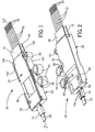
- a fanout connector generally designated 20 and which is fabricated of three major components.
- those components include a base housing, generally designated 22, and a cover, generally designated 24, which is slidably mounted onto the base housing in the direction of arrow "A".
- the base housing and cover form a housing means for receiving a third major component, namely a fanout insert, generally designated 26.
- a fiber optic cable 28 includes a plurality of individual optical fibers 30 which extends through the fanout insert and through a plurality of tubes 32 projecting forwardly of the insert.
- base housing 22 of fanout connector 20 includes a through passage, generally designated 34, for receiving cable 28 and fibers 30 along an axis 36.
- the base housing is a one-piece structure unitarily molded of plastic material and includes a bottom wall 38 and a pair of upstanding side walls 40 which define a receptacle 42 which communicates with or is a part of through passage 34.
- the receptacle generally is at a front end 44 of the housing, and a bottom lip 46 projects forwardly of front end 44.
- An entrance section 48 of through passage 34 opens at a rear end 50 of the housing and through which cable 28 extends. The entrance section is enlarged relative to the dimensions of the cable so that the cable is freely positioned within the enlarged entrance section as best seen in Figure 3.
- An intermediate section is defined by a pair of side walls 52 which gradually slope outwardly or diverge from entrance section 48 to receptacle 42.
- a plurality of guide rails 54 are located along the upper edges of side walls 40 of the base housing, with the guide rails opening inwardly toward axis 34.
- base housing 22 includes an upstanding octagonal mounting post 56, a rearwardly projecting strain relief tongue 58, a pair of upwardly opening latch recesses 60 (Fig. 4), a pair of bottom opening mounting holes 62 (Fig. 2) and a pair of cylindrical mounting members 64, all for purposes described hereinafter.
- Mounting members 64 are joined to one side wall 40 of the base housing by a pair of frangible webs 66.
- Cover 24 of connector 20 is a generally flat, elongated or rectangular member having guide ribs 68 along opposite edges thereof.
- the cover is a one-piece structure unitarily molded of plastic material.
- Guide ribs 68 slide beneath guide rails 54 of base housing 22 when the cover is slidably mounted to the housing in the direction of arrow "A" (Fig. 4) as described hereinafter.
- the cover has an upstanding octagonal mounting post 70 similar to upstanding mounting post 56 of the base housing.
- the cover has a forwardly projecting top lip 72 similar to bottom lip 46 of the base housing.
- the cover has a rearwardly projecting strain relief shroud 74 which cooperates with strain relief tongue 58 of the base housing to provide a strain relief means for cable 28, as will be seen hereinafter.
- the bottom of cover 24 has a pair of integrally molded latch bosses 76 which latch within recesses 60 (Fig. 4) of the base housing.
- a stop 78 also projects from the bottom of the cover.
- the cover includes a transparent window 80 which affords visual inspection of the cable within the connector.
- the entire cover may be molded of substantially transparent plastic material which is texturized in areas 82 so that substantially the entire cover is opaque except for transparent window 80.
- fanout insert 26 is molded of plastic material and includes a plurality of through holes 84 which receive fibers 30 of cable 28 and which spread the individual fibers apart from each other transversely of axis 36.
- the number of through holes does not have to match the number of fibers of the cable.
- the fibers extend through a plurality of tubes 32 projecting from a front end 86 of the fanout insert.
- the rear ends of the tubes preferably are fixed, as by epoxy, within the front ends of through holes 84.
- the fiber ends project beyond the front ends of the tubes as seen in the drawings.
- the tubes provide both protection for the projecting fibers as well as means for readily manipulating the fibers.
- the tubes themselves, are protected by forwardly projecting top lip 72 of the cover and bottom lip 46 of the base housing.
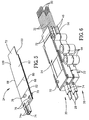
- Figure 6 shows how a plurality of connectors 20 can be mounted on top of each other in a stacked array.
- mounting post 56 which projects upwardly from base housing 22
- mounting post 70 which projects upwardly from cover 24 of a bottom connector are inserted into mounting holes 62 (Fig. 2) in the bottom of the base housing of a top connector. Therefore, the cover of the bottom connector cannot move relative to the base housing thereof.
- the mounting posts may be sized for positioning into the mounting holes by a press-fit.
- Figure 6 shows two connectors in a stacked array, of course more than two connectors can be stacked as described.
- the mounting posts 56 and 70 may be press fit into mounting holes in a printed circuit board (not shown).
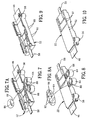
- FIGs 7-10 show how cylindrical mounting members 64 can be broken-away from base housing 22 for using the connector in applications wherein the connector is not mounted to a supporting structure.
- cylindrical mounting members 64 have through holes 88 (Figs. 7 and 8) for receiving therethrough appropriate fasteners, such as rivets, screws or bolts, for fastening the connector to an appropriate support structure.
- mounting members 64 are broken-away from base housing 22. This is accomplished by using frangible webs 66 which join the mounting members to the base housing and which are much smaller than the mounting members.
- Figures 7 and 7A show that notches 90 are formed at the tops of the webs immediately adjacent the housing.
- FIGs 8 and 8A show that notches 92 are formed at the bottoms of the webs immediately adjacent the housing. These notches weaken the junctures between the webs and the housing so that the webs readily break away from the housing leaving fairly clean breaking points as seen in Figures 9 and 10.
- fanout insert 26 includes a plurality of polarizing projections 94 on opposite sides thereof, and base housing 22 includes a plurality of polarizing projections 96 on the opposite sides of receptacle 42 defined by side walls 40.
- These complementary interengaging polarizing projections 94 and 96 define a tongue and groove arrangement at the sides of fanout insert 26 and the sides of receptacle 42 to ensure that the fanout insert is positioned in the receptacle only in a given orientation so that the fibers of cable 28 are oriented according to an expected scheme in which they have been threaded through the insert and through tubes 32.
- a small tube or band 98 is positioned about cable 28 at a point where the outer cladding of the cable has been removed to expose individual fibers 30.
- This band may be fabricated of heat shrinkable material and heat shrunk about the cable at this point. The band prevents the fibers from fraying the outer cladding of the cable after they have been exposed for spreading by fanout insert 26.
- the band is free to move within enlarged entrance section 48. This allows the cable and fibers to move axially of the entire connector within the limits of the band captured in the enlarged entrance section. Stop 78 on the underside of cover 24 defines the forward limit of such movement.
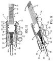
- cover 24 is assembled to the base housing as shown in Figures 13 and 14. Specifically, the cover is slidably mounted to the base housing in the direction of arrows "A". During mounting, guide ribs 68 at opposite edges of the flat cover slide beneath guide rails 54 along the top edges of side walls 40 of the base housing. The cover is slidably mounted to the housing until a pair of stops 100 at opposite sides of the cover abut against a pair of stops 102 at opposite sides of the base housing as seen in Figure 1.
- cover 24 is fully slidably mounted onto base housing 22 with stops 100 and 102 in abutment, two functions occur as best seen in Figure 15.
- latch bosses 76 (Fig. 5) on the underside of cover 24 snap into latching interengagement with latch recesses 60 (Fig. 4) in the top of the base housing.
- strain relief tongue 58 at the rear of the base housing enters strain relief shroud 74 at the rear of the cover. This sandwiches cable 28 between the tongue and the cover.
- shroud 74 is flattened and is generally C-shaped to define a pair of bottom, inwardly directed flanges 74a.
- Tongue 58 also is flat, whereby ribbon cable 28 is sandwiched between the flat tongue and the flat top of the shroud, with flanges 74a of the shroud interengaging with the bottom of the tongue.
- the shroud is joined to the cover by a thin web 74b.
- web 74b of shroud 74 and tongue 58 are flexible whereby the interengaged strain relief means provide strain relief for the cable.
- the size and location of latch bosses 76 and latch recesses 60 in relation to tongue 58 and shroud 74 preferably should be such that the tongue enters the shroud before the latch bosses of the cover engage the base housing which, otherwise, might move the tongue and shroud out of alignment. This can be seen in Figure 15 where tongue 58 has entered shroud 54 before latch bosses 76 engage the housing for movement into the latch recesses.
- Figure 16 shows a connector 20A which does not include mounting post 56 (Fig. 4) on base housing 22 nor mounting post 70 (Fig. 4) on cover 24. This simply shows that the connector can be made for non-stackable applications.
Landscapes
- Physics & Mathematics (AREA)
- General Physics & Mathematics (AREA)
- Optics & Photonics (AREA)
- Mechanical Coupling Of Light Guides (AREA)
- Light Guides In General And Applications Therefor (AREA)
- Details Of Connecting Devices For Male And Female Coupling (AREA)
Applications Claiming Priority (2)
| Application Number | Priority Date | Filing Date | Title |
|---|---|---|---|
| US602975 | 2000-06-23 | ||
| US09/602,975 US6623173B1 (en) | 2000-06-23 | 2000-06-23 | Fiber optic connector |
Publications (2)
| Publication Number | Publication Date |
|---|---|
| EP1168017A2 true EP1168017A2 (fr) | 2002-01-02 |
| EP1168017A3 EP1168017A3 (fr) | 2004-06-23 |
Family
ID=24413540
Family Applications (1)
| Application Number | Title | Priority Date | Filing Date |
|---|---|---|---|
| EP01114648A Ceased EP1168017A3 (fr) | 2000-06-23 | 2001-06-19 | Connecteur à fibres optiques |
Country Status (6)
| Country | Link |
|---|---|
| US (1) | US6623173B1 (fr) |
| EP (1) | EP1168017A3 (fr) |
| JP (1) | JP3577528B2 (fr) |
| KR (1) | KR100414845B1 (fr) |
| CN (2) | CN1213320C (fr) |
| TW (1) | TW501737U (fr) |
Cited By (1)
| Publication number | Priority date | Publication date | Assignee | Title |
|---|---|---|---|---|
| US7134200B2 (en) * | 2000-11-01 | 2006-11-14 | International Business Machines Corporation | Device and method for identifying cables |
Families Citing this family (48)
| Publication number | Priority date | Publication date | Assignee | Title |
|---|---|---|---|---|
| US20030053772A1 (en) * | 2001-09-18 | 2003-03-20 | Mitsubishi Cable Industries, Ltd. | Optical fiber sheet, method of manufacturing the same, and optical fiber interconnector |
| US6769811B2 (en) * | 2002-09-03 | 2004-08-03 | Stratos International, Inc. | Multi-fiber optic device |
| US6985665B2 (en) * | 2002-12-16 | 2006-01-10 | Tyco Electronics Corporation | Strain relief unit for fiber shuffling device |
| USD514520S1 (en) * | 2003-08-05 | 2006-02-07 | Bahram Bahramian | Fiber optic splitter |
| US7184635B2 (en) | 2004-06-04 | 2007-02-27 | Commscope Solutions Properties, Llc | Optical fiber array connectivity system utilizing angle polished ferrules and aligned-key adapters and cable for same |
| JP4544928B2 (ja) * | 2004-07-16 | 2010-09-15 | スリーエム イノベイティブ プロパティズ カンパニー | 光コネクタ及び光ファイバ接続システム |
| JP4416591B2 (ja) * | 2004-07-16 | 2010-02-17 | スリーエム イノベイティブ プロパティズ カンパニー | 光コネクタ及び光ファイバ接続システム |
| US7149392B2 (en) * | 2004-08-30 | 2006-12-12 | Molex Incorporated | Round multi-fiber cable assembly and a method of forming same |
| US7121732B2 (en) * | 2004-10-25 | 2006-10-17 | Panduit Corp. | Collet assembly with ribbon fiber holder |
| US20060233507A1 (en) * | 2005-04-14 | 2006-10-19 | Elli Makrides-Saravanos | Methods and apparatus for splitter modules and splitter module housings |
| US7416347B2 (en) * | 2005-05-31 | 2008-08-26 | Commscope Solutions Properties, Llc | Optical fiber array connectivity system with indicia to facilitate connectivity in four orientations for dual functionality |
| US10578812B2 (en) | 2005-06-08 | 2020-03-03 | Commscope, Inc. Of North Carolina | Methods for forming connectorized fiber optic cabling |
| US7537393B2 (en) | 2005-06-08 | 2009-05-26 | Commscope, Inc. Of North Carolina | Connectorized fiber optic cabling and methods for forming the same |
| US8992098B2 (en) | 2005-06-08 | 2015-03-31 | Commscope, Inc. Of North Carolina | Methods for forming connectorized fiber optic cabling |
| US7742667B2 (en) | 2005-06-08 | 2010-06-22 | Commscope, Inc. Of North Carolina | Fiber optic cables and methods for forming the same |
| KR100724076B1 (ko) * | 2005-12-16 | 2007-06-04 | 네트워크케이블 주식회사 | 현장조립형 광커넥터 |
| JP4269291B2 (ja) * | 2006-01-27 | 2009-05-27 | セイコーエプソン株式会社 | 光モジュール |
| US7664363B1 (en) | 2008-06-25 | 2010-02-16 | Mowery Sr Arthur J | Apparatus and method to protect fiber ribbons |
| US8573855B2 (en) | 2008-10-06 | 2013-11-05 | Adc Telecommunications, Inc. | Fanout cable assembly and method |
| DE102008062535A1 (de) * | 2008-12-16 | 2010-06-17 | Adc Gmbh | Micro-Distribution-Kabel für die optische Nachrichtentechnik und Verfahren zur Herstellung eines Micro-Distribution-Kabels |
| JP2011017985A (ja) * | 2009-07-10 | 2011-01-27 | Molex Inc | 光コネクタ組立体、光コネクタ組立体用のケーブル及び光コネクタ組立体用のプラグ |
| JP2011022198A (ja) | 2009-07-13 | 2011-02-03 | Molex Inc | 光コネクタ |
| JP5290074B2 (ja) | 2009-07-13 | 2013-09-18 | モレックス インコーポレイテド | 光コネクタ |
| US8705930B2 (en) * | 2010-06-25 | 2014-04-22 | Adc Telecommunications, Inc. | Transition housing and cap for fiber breakout assembly |
| US8625952B2 (en) | 2011-07-13 | 2014-01-07 | Corning Cable Systems Llc | Fiber optic cable mounting adapters, and related fiber optic cable assemblies and methods |
| SG11201407658WA (en) * | 2012-05-15 | 2015-01-29 | Bright Technologies Llc | Inspectable synthetic tensile member assembly |
| US10167928B2 (en) * | 2013-05-15 | 2019-01-01 | Bright Technologies, L.L.C. | Inspectable synthetic tensile member assembly |
| DE102012020589A1 (de) * | 2012-10-22 | 2014-04-24 | Reichle + De-Massari Ag | Verbindungsvorrichtung |
| DE102012020590A1 (de) * | 2012-10-22 | 2014-04-24 | Reichle + De-Massari Ag | Verbindungsvorrichtung |
| KR101341588B1 (ko) | 2013-05-27 | 2013-12-13 | 이정민 | 세경케이블용 다분기함과 이를 이용한 다분기세트 |
| KR101658422B1 (ko) * | 2014-04-16 | 2016-09-21 | 주식회사 라바텍 | 과학화 경계시스템의 광케이블용 유지보수 장치 |
| EP3001231B1 (fr) | 2014-09-26 | 2018-02-28 | CCS Technology, Inc. | Appareil et procédé d'insertion de fibres optiques dans des tubes |
| US10054753B2 (en) | 2014-10-27 | 2018-08-21 | Commscope Technologies Llc | Fiber optic cable with flexible conduit |
| CN105676380B (zh) | 2014-11-21 | 2019-07-12 | 泰科电子(上海)有限公司 | 光缆布线系统和光缆连接组件 |
| CN204462469U (zh) * | 2015-01-07 | 2015-07-08 | 泰科电子(上海)有限公司 | 光缆扇出器 |
| AU2015207954C1 (en) | 2015-07-31 | 2022-05-05 | Adc Communications (Australia) Pty Limited | Cable breakout assembly |
| CN108780200B (zh) | 2016-03-18 | 2021-05-07 | 康普技术有限责任公司 | 光纤电缆扇出管道结构、部件和方法 |
| US10890730B2 (en) | 2016-08-31 | 2021-01-12 | Commscope Technologies Llc | Fiber optic cable clamp and clamp assembly |
| US10914909B2 (en) | 2016-10-13 | 2021-02-09 | Commscope Technologies Llc | Fiber optic breakout transition assembly incorporating epoxy plug and cable strain relief |
| EP3622336A4 (fr) | 2017-05-08 | 2021-01-20 | Commscope Technologies LLC | Ensemble de transition de dérivation de fibres optiques |
| US10110311B1 (en) * | 2017-10-02 | 2018-10-23 | Prime World International Holdings Ltd. | Optical transceiver |
| US10459179B2 (en) | 2017-10-04 | 2019-10-29 | Prime World International Holdings Ltd. | Optical transceiver and optical lens thereof |
| US10151891B1 (en) | 2017-10-24 | 2018-12-11 | Prime World International Holdings Ltd. | Optical transceiver |
| US10330881B1 (en) * | 2017-12-21 | 2019-06-25 | Afl Telecommunications Llc | Optical fiber furcation assemblies |
| CN107942440B (zh) * | 2018-01-02 | 2024-01-30 | 任丘市志强塑料制品有限公司 | 一种微型光纤热缩管及其生产工艺 |
| JP6622338B2 (ja) * | 2018-03-12 | 2019-12-18 | 株式会社フジクラ | 光コネクタ及び光コネクタの極性変換方法 |
| US11175465B2 (en) | 2019-03-02 | 2021-11-16 | Senko Advanced Components, Inc. | Fiber management enclosure for a fiber optic connector assembly and method of use |
| US12460699B2 (en) * | 2022-05-27 | 2025-11-04 | Wireco Worldgroup Inc. | Cable termination inspection cover assembly |
Family Cites Families (25)
| Publication number | Priority date | Publication date | Assignee | Title |
|---|---|---|---|---|
| US3002175A (en) * | 1958-09-24 | 1961-09-26 | Burndy Corp | Electrical connector housing |
| US3999826A (en) * | 1975-06-30 | 1976-12-28 | General Motors Corporation | Connector for flexible printed circuit |
| US4167303A (en) * | 1977-07-28 | 1979-09-11 | Amp Incorporated | Light transmitting fiber cable connector |
| US5166995A (en) * | 1984-06-08 | 1992-11-24 | Amp Incorporated | Polarized connector |
| EP0307518B1 (fr) * | 1984-06-08 | 1993-07-28 | The Whitaker Corporation | Connecteurs à fibre optique à haute précision |
| US4818059A (en) * | 1986-03-14 | 1989-04-04 | Sumitomo Electric Industries, Ltd. | Optical connector and splicer |
| JPS63287917A (ja) * | 1987-05-21 | 1988-11-25 | Fujikura Ltd | 光ファイバコネクタ及びその着脱方法 |
| US5134675A (en) * | 1990-12-18 | 1992-07-28 | Abbott Laboratories | Beveled angle fiber optic connector |
| WO1993007659A1 (fr) * | 1991-10-09 | 1993-04-15 | Ifax Corporation | Systeme d'interconnection directe de circuits integres |
| US5194018A (en) * | 1992-01-22 | 1993-03-16 | Molex Incorporated | Electrical connector assembly and method of fabricating same |
| US5288113A (en) * | 1992-12-24 | 1994-02-22 | Restek Corporation | Connector for capillary tubes having a tapered inner bore |
| US5358422A (en) * | 1993-02-11 | 1994-10-25 | Marquette Electronics, Inc. | Terminal assembly |
| US5312261A (en) * | 1993-02-16 | 1994-05-17 | Molex Incorporated | Programmable input-output electrical connector |
| JPH07134222A (ja) * | 1993-11-11 | 1995-05-23 | Furukawa Electric Co Ltd:The | 光コネクタ |
| JPH08110439A (ja) * | 1994-08-18 | 1996-04-30 | Furukawa Electric Co Ltd:The | ピン挿入部材 |
| US5471555A (en) * | 1994-11-21 | 1995-11-28 | Sumitomo Electric Lightwave Corp. | Fiber optic ribbon break-out device with enhanced strain relief |
| US5604830A (en) | 1994-12-22 | 1997-02-18 | Hoechst Celanese Corp. | Multiple fiber connector for injection molded multiple fiberoptic coupler unit and cladding for same |
| KR0184963B1 (ko) * | 1995-10-31 | 1999-05-15 | 유기범 | 다심 광 케이블 접속용 콘넥터 조립체 |
| US6122162A (en) * | 1996-06-28 | 2000-09-19 | Matsushita Electric Industrial Co., Ltd. | Portable device and concentrator therefor |
| JP3705883B2 (ja) * | 1996-12-04 | 2005-10-12 | 株式会社フジクラ | 光コネクタ |
| US5778122A (en) | 1996-12-24 | 1998-07-07 | Siecor Corporation | Fiber optic cable assembly for interconnecting optical fibers within a receptacle mounted within the wall of an enclosure |
| JP3283791B2 (ja) * | 1997-06-12 | 2002-05-20 | 矢崎総業株式会社 | コネクタ及びコネクタの製造方法 |
| US5915055A (en) | 1997-06-30 | 1999-06-22 | Siecor Corporation | Method and apparatus for connectorizing fiber optic cable |
| JPH11211938A (ja) * | 1998-01-23 | 1999-08-06 | Mitsubishi Cable Ind Ltd | 光コネクタ用クリップ |
| KR100290181B1 (ko) * | 1998-11-02 | 2001-05-15 | 김진찬 | 리본형 다심광섬유 분리형 광코드 |
-
2000
- 2000-06-23 US US09/602,975 patent/US6623173B1/en not_active Expired - Fee Related
-
2001
- 2001-06-19 EP EP01114648A patent/EP1168017A3/fr not_active Ceased
- 2001-06-20 JP JP2001225176A patent/JP3577528B2/ja not_active Expired - Fee Related
- 2001-06-22 CN CNB011248416A patent/CN1213320C/zh not_active Expired - Fee Related
- 2001-06-22 TW TW090210599U patent/TW501737U/zh not_active IP Right Cessation
- 2001-06-22 CN CNA200410048890XA patent/CN1548998A/zh active Pending
- 2001-06-23 KR KR10-2001-0036011A patent/KR100414845B1/ko not_active Expired - Fee Related
Cited By (2)
| Publication number | Priority date | Publication date | Assignee | Title |
|---|---|---|---|---|
| US7134200B2 (en) * | 2000-11-01 | 2006-11-14 | International Business Machines Corporation | Device and method for identifying cables |
| US7534129B2 (en) | 2000-11-01 | 2009-05-19 | International Business Machines Corporation | Device and method for identifying cables |
Also Published As
| Publication number | Publication date |
|---|---|
| JP3577528B2 (ja) | 2004-10-13 |
| US6623173B1 (en) | 2003-09-23 |
| TW501737U (en) | 2002-09-01 |
| CN1548998A (zh) | 2004-11-24 |
| EP1168017A3 (fr) | 2004-06-23 |
| CN1331423A (zh) | 2002-01-16 |
| KR100414845B1 (ko) | 2004-01-13 |
| KR20020001575A (ko) | 2002-01-09 |
| JP2002148481A (ja) | 2002-05-22 |
| CN1213320C (zh) | 2005-08-03 |
Similar Documents
| Publication | Publication Date | Title |
|---|---|---|
| US6623173B1 (en) | Fiber optic connector | |
| US6434316B1 (en) | Fiber optic connector | |
| EP1168016B1 (fr) | Connecteur pour fibres optiques | |
| US20230057049A1 (en) | Multifiber fiber optic connectors, cable assemblies and methods of making the same | |
| KR100204372B1 (ko) | 광섬유 커넥터용 어댑터 조립체 | |
| US6224268B1 (en) | Plug housing with attached cantilevered latch for a fiber optic connector | |
| US20200301085A1 (en) | Fiber Optic Connector Assembly, Apparatus For Forming A Transceiver Interface, And Ferrule | |
| EP1221630B1 (fr) | Assemblage d'un connecteur de montage flottant | |
| US5044719A (en) | Cable connector | |
| KR100411838B1 (ko) | 유동 커넥터 조립체 | |
| EP0997753A2 (fr) | Assemblage à connecteur fibre optique | |
| EP1014126A2 (fr) | Assemblage de connecteur | |
| US6227719B1 (en) | Plastic optical fiber connector | |
| EP2035874A1 (fr) | Connecteur optique | |
| CA1279176C (fr) | Dispositif a organe de sectionnement pour le raccordement de fibres optiques | |
| IE84943B1 (en) | An optical connector |
Legal Events
| Date | Code | Title | Description |
|---|---|---|---|
| PUAI | Public reference made under article 153(3) epc to a published international application that has entered the european phase |
Free format text: ORIGINAL CODE: 0009012 |
|
| AK | Designated contracting states |
Kind code of ref document: A2 Designated state(s): AT BE CH CY DE DK ES FI FR GB GR IE IT LI LU MC NL PT SE TR |
|
| AX | Request for extension of the european patent |
Free format text: AL;LT;LV;MK;RO;SI |
|
| RIN1 | Information on inventor provided before grant (corrected) |
Inventor name: MATASEK, JEFFREY A. Inventor name: MARRAPODE, THOMAS R. Inventor name: KIM, BYUNG Inventor name: GROIS, IGOR |
|
| PUAL | Search report despatched |
Free format text: ORIGINAL CODE: 0009013 |
|
| AK | Designated contracting states |
Kind code of ref document: A3 Designated state(s): AT BE CH CY DE DK ES FI FR GB GR IE IT LI LU MC NL PT SE TR |
|
| AX | Request for extension of the european patent |
Extension state: AL LT LV MK RO SI |
|
| 17P | Request for examination filed |
Effective date: 20040728 |
|
| 17Q | First examination report despatched |
Effective date: 20041015 |
|
| AKX | Designation fees paid |
Designated state(s): DE FR GB IT |
|
| STAA | Information on the status of an ep patent application or granted ep patent |
Free format text: STATUS: THE APPLICATION HAS BEEN REFUSED |
|
| 18R | Application refused |
Effective date: 20060304 |