EP1168018A2 - Faseroptischer Verbinder - Google Patents
Faseroptischer Verbinder Download PDFInfo
- Publication number
- EP1168018A2 EP1168018A2 EP01114692A EP01114692A EP1168018A2 EP 1168018 A2 EP1168018 A2 EP 1168018A2 EP 01114692 A EP01114692 A EP 01114692A EP 01114692 A EP01114692 A EP 01114692A EP 1168018 A2 EP1168018 A2 EP 1168018A2
- Authority
- EP
- European Patent Office
- Prior art keywords
- connector
- housing
- cover
- fanout
- base housing
- Prior art date
- Legal status (The legal status is an assumption and is not a legal conclusion. Google has not performed a legal analysis and makes no representation as to the accuracy of the status listed.)
- Withdrawn
Links
- 239000000835 fiber Substances 0.000 title claims abstract description 47
- 230000000295 complement effect Effects 0.000 claims abstract description 18
- 239000013307 optical fiber Substances 0.000 claims abstract description 15
- 230000004044 response Effects 0.000 claims abstract description 7
- 230000007480 spreading Effects 0.000 claims description 5
- 230000005540 biological transmission Effects 0.000 claims description 2
- 239000000463 material Substances 0.000 description 6
- 229920003023 plastic Polymers 0.000 description 5
- 230000000712 assembly Effects 0.000 description 3
- 238000000429 assembly Methods 0.000 description 3
- 238000005253 cladding Methods 0.000 description 2
- 230000001351 cycling effect Effects 0.000 description 2
- 239000004593 Epoxy Substances 0.000 description 1
- 238000005452 bending Methods 0.000 description 1
- 239000000919 ceramic Substances 0.000 description 1
- 239000002654 heat shrinkable material Substances 0.000 description 1
- 238000011179 visual inspection Methods 0.000 description 1
Images


Classifications
-
- G—PHYSICS
- G02—OPTICS
- G02B—OPTICAL ELEMENTS, SYSTEMS OR APPARATUS
- G02B6/00—Light guides; Structural details of arrangements comprising light guides and other optical elements, e.g. couplings
- G02B6/24—Coupling light guides
- G02B6/36—Mechanical coupling means
-
- G—PHYSICS
- G02—OPTICS
- G02B—OPTICAL ELEMENTS, SYSTEMS OR APPARATUS
- G02B6/00—Light guides; Structural details of arrangements comprising light guides and other optical elements, e.g. couplings
- G02B6/24—Coupling light guides
- G02B6/36—Mechanical coupling means
- G02B6/38—Mechanical coupling means having fibre to fibre mating means
- G02B6/3807—Dismountable connectors, i.e. comprising plugs
- G02B6/3887—Anchoring optical cables to connector housings, e.g. strain relief features
-
- G—PHYSICS
- G02—OPTICS
- G02B—OPTICAL ELEMENTS, SYSTEMS OR APPARATUS
- G02B6/00—Light guides; Structural details of arrangements comprising light guides and other optical elements, e.g. couplings
- G02B6/24—Coupling light guides
- G02B6/36—Mechanical coupling means
- G02B6/38—Mechanical coupling means having fibre to fibre mating means
- G02B6/3807—Dismountable connectors, i.e. comprising plugs
- G02B6/3873—Connectors using guide surfaces for aligning ferrule ends, e.g. tubes, sleeves, V-grooves, rods, pins, balls
- G02B6/3874—Connectors using guide surfaces for aligning ferrule ends, e.g. tubes, sleeves, V-grooves, rods, pins, balls using tubes, sleeves to align ferrules
- G02B6/3878—Connectors using guide surfaces for aligning ferrule ends, e.g. tubes, sleeves, V-grooves, rods, pins, balls using tubes, sleeves to align ferrules comprising a plurality of ferrules, branching and break-out means
- G02B6/3879—Linking of individual connector plugs to an overconnector, e.g. using clamps, clips, common housings comprising several individual connector plugs
-
- G—PHYSICS
- G02—OPTICS
- G02B—OPTICAL ELEMENTS, SYSTEMS OR APPARATUS
- G02B6/00—Light guides; Structural details of arrangements comprising light guides and other optical elements, e.g. couplings
- G02B6/24—Coupling light guides
- G02B6/36—Mechanical coupling means
- G02B6/38—Mechanical coupling means having fibre to fibre mating means
- G02B6/3807—Dismountable connectors, i.e. comprising plugs
- G02B6/3873—Connectors using guide surfaces for aligning ferrule ends, e.g. tubes, sleeves, V-grooves, rods, pins, balls
- G02B6/3885—Multicore or multichannel optical connectors, i.e. one single ferrule containing more than one fibre, e.g. ribbon type
-
- G—PHYSICS
- G02—OPTICS
- G02B—OPTICAL ELEMENTS, SYSTEMS OR APPARATUS
- G02B6/00—Light guides; Structural details of arrangements comprising light guides and other optical elements, e.g. couplings
- G02B6/44—Mechanical structures for providing tensile strength and external protection for fibres, e.g. optical transmission cables
- G02B6/4439—Auxiliary devices
- G02B6/4471—Terminating devices ; Cable clamps
- G02B6/44715—Fan-out devices
-
- G—PHYSICS
- G02—OPTICS
- G02B—OPTICAL ELEMENTS, SYSTEMS OR APPARATUS
- G02B6/00—Light guides; Structural details of arrangements comprising light guides and other optical elements, e.g. couplings
- G02B6/24—Coupling light guides
- G02B6/36—Mechanical coupling means
- G02B6/38—Mechanical coupling means having fibre to fibre mating means
- G02B6/3807—Dismountable connectors, i.e. comprising plugs
- G02B6/3869—Mounting ferrules to connector body, i.e. plugs
- G02B6/387—Connector plugs comprising two complementary members, e.g. shells, caps, covers, locked together
Definitions
- This invention generally relates to the art of connector assemblies and, particularly, to a fiber optic connector assembly, but certain features of the invention may be equally applicable for use with other types of connectors such as electrical connectors.
- Fiber optic connectors of a wide variety of designs have been employed to terminate optical fiber cables and to facilitate connection of the cables to other cables or other optical fiber transmission devices.
- a typical fiber optic connector includes a ferrule which mounts and centers an optical fiber or fibers within the connector. The ferrule may be fabricated of such material as ceramics.
- a multi-fiber optic cable is terminated in the connector, and a plurality of individual optical fibers of the cable may be terminated in the ferrule.
- a popular type of fiber optic cable is a multi-fiber flat cable which conventionally is called a ribbon cable.
- a fanout connector typically is used with a ribbon-type cable.
- the individual optical fibers of the cable are very closely spaced.
- a fanout connector includes a fanout means such as a fanout insert for receiving and spreading the individual fibers of the cable transversely thereof so that the fibers are more easily connectorized according to hardware interface requirements.
- the individual fibers extend away from the fanout insert within a plurality of easily manipulatable tubes which also protect the fibers.
- the tubes often are color-coded and are permanently affixed to a fanout structure by, for example, heat shrinking. This type of attachment may degrade the temperature cycling performance by causing micro bending of the fibers.
- the present invention is directed to providing various improvements in connector assemblies, such as fiber optic connector assemblies, including fanout-type fiber optic connectors.
- An object, therefore, of the invention is to provide a new and improved connector assembly, such as a fiber optic fanout connector, of the character described.
- a fanout connector assembly for a fiber optic cable including a plurality of optical fibers.
- the assembly includes at least two fanout connectors each including a housing having a passage for receiving a fiber optic cable along an axis.
- the housing has a fanout member for spreading the individual optical fibers of the fiber optic cable transversely of the axis.
- Complementary interengaging stacking members are provided on the housing of the two connectors for aligning and holding the connectors in stacked relationship with one connector on top of the other connector.
- the complementary interengaging stacking members comprise at least one mounting post on the housing of one of the connectors received in a mounting hole in the housing of the other connector.
- a plurality of the mounting posts are received in a plurality of the mounting holes.
- the posts may be sized relative to the holes for receipt therein by a press-fit.
- the posts may also be adapted to be press fit into mounting holes in a printed circuit board.
- the housing for each connector includes a base housing and a cover with at least one of the mounting post and the mounting hole being on each of the base housing and cover.
- the base housing and the cover of one connector each includes an upstanding mounting base, and the base housing of the other connector includes a pair of mounting holes for receiving the mounting posts.
- the cover is shown herein slidably mounted on the base housing generally parallel to the axis, whereby the cover is rendered immovable when the connectors are stacked.
- the base housing and the cover have complementary interengaging latch members for interengagement automatically in response to slidably mounting the cover onto the base housing.
- Complementary interengaging cable strain relief members also are provided between the base housing and cover for interengagement automatically in response to slidably mounting the cover onto the base housing.
- the latch members and the strain relief members are located relative to each other whereby the strain relief members are at least partially interengaged prior to interengagement of the latch members.
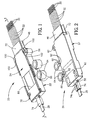
- a fanout connector generally designated 20 and which is fabricated of three major components.
- those components include a base housing, generally designated 22, and a cover, generally designated 24, which is slidably mounted onto the base housing in the direction of arrow "A".
- the base housing and cover form a housing means for receiving a third major component, namely a fanout insert, generally designated 26.
- a fiber optic cable 28 includes a plurality of individual optical fibers 30 which extend through the fanout insert and through a plurality of tubes 32 projecting forwardly of the insert.
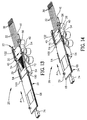
- base housing 22 of fanout connector 20 includes a through passage, generally designated 34, for receiving cable 28 and fibers 30 along an axis 36.
- the base housing is a one-piece structure unitarily molded of plastic material and includes a bottom wall 38 and a pair of upstanding side walls 40 which define a receptacle 42 which communicates with or is a part of through passage 34.
- the receptacle generally is at a front end 44 of the housing, and a bottom lip 46 projects forwardly of front end 44.
- An entrance section 48 of through passage 34 opens at a rear end 50 of the housing and through which cable 28 extends. The entrance section is enlarged relative to the dimensions of the cable so that the cable is freely positioned within the enlarged entrance section as best seen in Figure 3.
- An intermediate section is defined by a pair of side walls 52 which gradually slope outwardly or diverge from entrance section 48 to receptacle 42.
- a plurality of guide rails 54 are located along the upper edges of side walls 40 of the base housing, with the guide rails opening inwardly toward axis 34.
- base housing 22 includes an upstanding octagonal mounting post 56, a rearwardly projecting strain relief tongue 58, a pair of upwardly opening latch recesses 60 (Fig. 4), a pair of bottom opening mounting holes 62 (Fig. 2) and a pair of cylindrical mounting members 64, all for purposes described hereinafter.
- Mounting members 64 are joined to one side wall 40 of the base housing by a pair of frangible webs 66.
- Cover 24 of connector 20 is a generally flat, elongated or rectangular member having guide ribs 68 along opposite edges thereof.
- the cover is a one-piece structure unitarily molded of plastic material.
- Guide ribs 68 slide beneath guide rails 54 of base housing 22 when the cover is slidably mounted to the housing in the direction of arrow "A" (Fig. 4) as described hereinafter.
- the cover has an upstanding octagonal mounting post 70 similar to upstanding mounting post 56 of the base housing.
- the cover has a forwardly projecting top lip 72 similar to bottom lip 46 of the base housing.
- the cover has a rearwardly projecting strain relief shroud 74 which cooperates with strain relief tongue 58 of the base housing to provide a strain relief means for cable 28, as will be seen hereinafter.
- the bottom of cover 24 has a pair of integrally molded latch bosses 76 which latch within recesses 60 (Fig. 4) of the base housing.
- a stop 78 also projects from the bottom of the cover.
- the cover includes a transparent window 80 which affords visual inspection of the cable within the connector.
- the entire cover may be molded of substantially transparent plastic material which is texturized in areas 82 so that substantially the entire cover is opaque except for transparent window 80.
- fanout insert 26 is molded of plastic material and includes a plurality of through holes 84 which receive fibers 30 of cable 28 and which spread the individual fibers apart from each other transversely of axis 36.
- the number of through holes does not have to match the number of fibers of the cable.
- the fibers extend through a plurality of tubes 32 projecting from a front end 86 of the fanout insert.
- the rear ends of the tubes preferably are fixed, as by epoxy, within the front ends of through holes 84.
- the fiber ends project beyond the front ends of the tubes as seen in the drawings.
- the tubes provide both protection for the projecting fibers as well as means for readily manipulating the fibers.
- the tubes themselves, are protected by forwardly projecting top lip 72 of the cover and bottom lip 46 of the base housing.
- Figure 6 shows how a plurality of connectors 20 can be mounted on top of each other in a stacked array.
- mounting post 56 which projects upwardly from base housing 22
- mounting post 70 which projects upwardly from cover 24 of a bottom connector are inserted into mounting holes 62 (Fig. 2) in the bottom of the base housing of a top connector. Therefore, the cover of the bottom connector cannot move relative to the base housing thereof.
- the mounting posts may be sized for positioning into the mounting holes by a press-fit.
- Figure 6 shows two connectors in a stacked array, of course more than two connectors can be stacked as described.
- the mounting posts 56 and 70 may be press fit into mounting holes in a printed circuit board (not shown).
- FIGs 7-10 show how cylindrical mounting members 64 can be broken-away from base housing 22 for using the connector in applications wherein the connector is not mounted to a supporting structure.
- cylindrical mounting members 64 have through holes 88 (Figs. 7 and 8) for receiving therethrough appropriate fasteners, such as rivets, screws or bolts, for fastening the connector to an appropriate support structure.
- mounting members 64 are broken-away from base housing 22. This is accomplished by using frangible webs 66 which join the mounting members to the base housing and which are much smaller than the mounting members.
- Figures 7 and 7A show that notches 90 are formed at the tops of the webs immediately adjacent the housing.
- FIGs 8 and 8A show that notches 92 are formed at the bottoms of the webs immediately adjacent the housing. These notches weaken the junctures between the webs and the housing so that the webs readily break away from the housing leaving fairly clean breaking points as seen in Figures 9 and 10.
- fanout insert 26 includes a plurality of polarizing projections 94 on opposite sides thereof, and base housing 22 includes a plurality of polarizing projections 96 on the opposite sides of receptacle 42 defined by side walls 40.
- These complementary interengaging polarizing projections 94 and 96 define a tongue and groove arrangement at the sides of fanout insert 26 and the sides of receptacle 42 to ensure that the fanout insert is positioned in the receptacle only in a given orientation so that the fibers of cable 28 are oriented according to an expected scheme in which they have been threaded through the insert and through tubes 32.
- a small tube or band 98 is positioned about cable 28 at a point where the outer cladding of the cable has been removed to expose individual fibers 30.
- This band may be fabricated of heat shrinkable material and heat shrunk about the cable at this point. The band prevents the fibers from fraying the outer cladding of the cable after they have been exposed for spreading by fanout insert 26.
- the band is free to move within enlarged entrance section 48. This allows the cable and fibers to move axially of the entire connector within the limits of the band captured in the enlarged entrance section thereby improving temperature cycling performance. Stop 78 on the underside of cover 24 defines the forward limit of such movement.
- cover 24 is assembled to the base housing as shown in Figures 13 and 14. Specifically, the cover is slidably mounted to the base housing in the direction of arrows "A". During mounting, guide ribs 68 at opposite edges of the flat cover slide beneath guide rails 54 along the top edges of side walls 40 of the base housing. The cover is slidably mounted to the housing until a pair of stops 100 at opposite sides of the cover abut against a pair of stops 102 at opposite sides of the base housing as seen in Figure 1.
- cover 24 is fully slidably mounted onto base housing 22 with stops 100 and 102 in abutment, two functions occur as best seen in Figure 15.
- latch bosses 76 (Fig. 5) on the underside of cover 24 snap into latching interengagement with latch recesses 60 (Fig. 4) in the top of the base housing.
- strain relief tongue 58 at the rear of the base housing enters strain relief shroud 74 at the rear of the cover. This sandwiches cable 28 between the tongue and the cover.
- shroud 74 is flattened and is generally C-shaped to define a pair of bottom, inwardly directed flanges 74a.
- Tongue 58 also is flat, whereby ribbon cable 28 is sandwiched between the flat tongue and the flat top of the shroud, with flanges 74a of the shroud interengaging with the bottom of the tongue.
- the shroud is joined to the cover by a thin web 74b.
- web 74b of shroud 74 and tongue 58 are flexible whereby the interengaged strain relief means provide strain relief for the cable.
- the size and location of latch bosses 76 and latch recesses 60 in relation to tongue 58 and shroud 74 preferably should be such that the tongue enters the shroud before the latch bosses of the cover engage the base housing which, otherwise, might move the tongue and shroud out of alignment. This can be seen in Figure 15 where tongue 58 has entered shroud 54 before latch bosses 76 engage the housing for movement into the latch recesses.
- Figure 16 shows a connector 20A which does not include mounting post 56 (Fig. 4) on base housing 22 nor mounting post 70 (Fig. 4) on cover 24. This simply shows that the connector can be made for non-stackable applications.
Landscapes
- Physics & Mathematics (AREA)
- General Physics & Mathematics (AREA)
- Optics & Photonics (AREA)
- Mechanical Coupling Of Light Guides (AREA)
- Light Guides In General And Applications Therefor (AREA)
- Details Of Connecting Devices For Male And Female Coupling (AREA)
- Multi-Conductor Connections (AREA)
- Coupling Device And Connection With Printed Circuit (AREA)
Priority Applications (1)
| Application Number | Priority Date | Filing Date | Title |
|---|---|---|---|
| EP06023870A EP1752805A3 (de) | 2000-06-23 | 2001-06-19 | Faseroptischer Verbinder |
Applications Claiming Priority (2)
| Application Number | Priority Date | Filing Date | Title |
|---|---|---|---|
| US09/602,956 US6434316B1 (en) | 2000-06-23 | 2000-06-23 | Fiber optic connector |
| US602956 | 2000-06-23 |
Related Child Applications (1)
| Application Number | Title | Priority Date | Filing Date |
|---|---|---|---|
| EP06023870A Division EP1752805A3 (de) | 2000-06-23 | 2001-06-19 | Faseroptischer Verbinder |
Publications (2)
| Publication Number | Publication Date |
|---|---|
| EP1168018A2 true EP1168018A2 (de) | 2002-01-02 |
| EP1168018A3 EP1168018A3 (de) | 2004-12-01 |
Family
ID=24413449
Family Applications (2)
| Application Number | Title | Priority Date | Filing Date |
|---|---|---|---|
| EP06023870A Withdrawn EP1752805A3 (de) | 2000-06-23 | 2001-06-19 | Faseroptischer Verbinder |
| EP01114692A Withdrawn EP1168018A3 (de) | 2000-06-23 | 2001-06-19 | Faseroptischer Verbinder |
Family Applications Before (1)
| Application Number | Title | Priority Date | Filing Date |
|---|---|---|---|
| EP06023870A Withdrawn EP1752805A3 (de) | 2000-06-23 | 2001-06-19 | Faseroptischer Verbinder |
Country Status (6)
| Country | Link |
|---|---|
| US (1) | US6434316B1 (de) |
| EP (2) | EP1752805A3 (de) |
| JP (2) | JP3565189B2 (de) |
| KR (1) | KR100424836B1 (de) |
| CN (2) | CN1213319C (de) |
| TW (1) | TW500229U (de) |
Cited By (13)
| Publication number | Priority date | Publication date | Assignee | Title |
|---|---|---|---|---|
| WO2009040564A1 (en) * | 2007-09-24 | 2009-04-02 | Tyco Electronics Raychem Nv | Array of adaptors for optical connectors |
| EP2482108A1 (de) * | 2011-01-31 | 2012-08-01 | Tyco Electronics Raychem BVBA | Kabelsteckeranordnung |
| WO2015091865A3 (en) * | 2013-12-18 | 2015-12-03 | Tyco Electronics Raychem Bvba | Cable fixation devices and methods |
| US20200012047A1 (en) | 2017-03-21 | 2020-01-09 | Corning Research & Development Corporation | Fiber optic cable assembly with thermoplastically overcoated fusion splice, and related method and apparatus |
| WO2020051034A1 (en) * | 2018-09-07 | 2020-03-12 | Corning Incorporated | Optical fiber fan-out assembly with ribbonized interface for mass fusion splicing, and fabrication method |
| US10976492B2 (en) | 2018-09-07 | 2021-04-13 | Corning Incorporated | Cable with overcoated non-coplanar groups of fusion spliced optical fibers, and fabrication method |
| US11314030B2 (en) | 2017-10-09 | 2022-04-26 | CommScope Connectivity Belgium BVBA | Cable fixation devices and methods |
| US11360265B2 (en) | 2019-07-31 | 2022-06-14 | Corning Research & Development Corporation | Fiber optic cable assembly with overlapping bundled strength members, and fabrication method and apparatus |
| US11808983B2 (en) | 2020-11-24 | 2023-11-07 | Corning Research & Development Corporation | Multi-fiber splice protector with compact splice-on furcation housing |
| US11867947B2 (en) | 2021-04-30 | 2024-01-09 | Corning Research & Development Corporation | Cable assembly having routable splice protectors |
| US11886009B2 (en) | 2020-10-01 | 2024-01-30 | Corning Research & Development Corporation | Coating fusion spliced optical fibers and subsequent processing methods thereof |
| EP4692878A1 (de) * | 2024-08-09 | 2026-02-11 | ODU GmbH & Co KG. | Modulares verbindergehäuse |
| US12591098B2 (en) | 2021-02-25 | 2026-03-31 | Commscope Technologies Llc | Sheath termination and ribbon orienting devices and methods for flat optical fiber ribbons |
Families Citing this family (47)
| Publication number | Priority date | Publication date | Assignee | Title |
|---|---|---|---|---|
| US6769811B2 (en) * | 2002-09-03 | 2004-08-03 | Stratos International, Inc. | Multi-fiber optic device |
| US6963119B2 (en) * | 2003-05-30 | 2005-11-08 | International Business Machines Corporation | Integrated optical transducer assembly |
| US6827597B1 (en) | 2003-11-20 | 2004-12-07 | Pgs Americas, Inc. | Combined electrical and optical cable connector particularly suited for marine seismic sensor streamers |
| US7054536B2 (en) * | 2004-05-12 | 2006-05-30 | Molex Incorporated | Breakout assembly for flexible circuitry |
| US7184635B2 (en) * | 2004-06-04 | 2007-02-27 | Commscope Solutions Properties, Llc | Optical fiber array connectivity system utilizing angle polished ferrules and aligned-key adapters and cable for same |
| US7121732B2 (en) * | 2004-10-25 | 2006-10-17 | Panduit Corp. | Collet assembly with ribbon fiber holder |
| US7416347B2 (en) * | 2005-05-31 | 2008-08-26 | Commscope Solutions Properties, Llc | Optical fiber array connectivity system with indicia to facilitate connectivity in four orientations for dual functionality |
| US7254307B2 (en) * | 2005-06-03 | 2007-08-07 | Telect Inc. | Fiber breakout system |
| US7366391B2 (en) * | 2005-06-03 | 2008-04-29 | Telect Inc. | Hybrid wire-fiber management |
| US7460758B2 (en) * | 2005-06-03 | 2008-12-02 | Telect Inc. | Fiber management system |
| US7683270B2 (en) * | 2005-06-03 | 2010-03-23 | Telect Inc. | Telecommunications cabinet |
| US7742667B2 (en) | 2005-06-08 | 2010-06-22 | Commscope, Inc. Of North Carolina | Fiber optic cables and methods for forming the same |
| US8992098B2 (en) | 2005-06-08 | 2015-03-31 | Commscope, Inc. Of North Carolina | Methods for forming connectorized fiber optic cabling |
| US7537393B2 (en) | 2005-06-08 | 2009-05-26 | Commscope, Inc. Of North Carolina | Connectorized fiber optic cabling and methods for forming the same |
| US10578812B2 (en) | 2005-06-08 | 2020-03-03 | Commscope, Inc. Of North Carolina | Methods for forming connectorized fiber optic cabling |
| US8798427B2 (en) | 2007-09-05 | 2014-08-05 | Corning Cable Systems Llc | Fiber optic terminal assembly |
| EP2234217A4 (de) * | 2008-01-15 | 2011-06-29 | Fujikura Ltd | Wasserfester verbinder für ein flexibles substrat |
| US8290333B2 (en) | 2008-08-29 | 2012-10-16 | Corning Cable Systems Llc | Fiber optic cable assemblies with furcation bodies having features for manufacturing and methods of making the same |
| US8301004B2 (en) * | 2008-08-29 | 2012-10-30 | Corning Cable Systems Llc | Fiber optic cable assemblies employing a furcation body having anti-rotation feature |
| US8135257B2 (en) * | 2008-08-29 | 2012-03-13 | Corning Cable Systems Llc | Structures for managing and mounting cable assemblies |
| EP2344915A4 (de) | 2008-10-09 | 2015-01-21 | Corning Cable Sys Llc | Faseroptischer anschluss mit adaptertafel, die sowohl eingangs- als auch ausgangsfasern von einem optischen teiler unterstützt |
| JP5148446B2 (ja) * | 2008-10-10 | 2013-02-20 | 株式会社ジャパンリーコム | コネクタ収納ケース |
| US8879882B2 (en) | 2008-10-27 | 2014-11-04 | Corning Cable Systems Llc | Variably configurable and modular local convergence point |
| EP2237091A1 (de) | 2009-03-31 | 2010-10-06 | Corning Cable Systems LLC | Lösbar montierbares LWL-Leitungsendgerät |
| DE102009017815B4 (de) * | 2009-04-20 | 2021-09-09 | Phoenix Contact Gmbh & Co. Kg | Elektrische Anschlussklemme zum Durchführen einer Leitung duch eine Wandung |
| US8467651B2 (en) | 2009-09-30 | 2013-06-18 | Ccs Technology Inc. | Fiber optic terminals configured to dispose a fiber optic connection panel(s) within an optical fiber perimeter and related methods |
| US20110123159A1 (en) * | 2009-11-26 | 2011-05-26 | Hon Hai Precision Industry Co., Ltd. | Cable assembly having positioning means securing fiber thereof |
| US9547144B2 (en) | 2010-03-16 | 2017-01-17 | Corning Optical Communications LLC | Fiber optic distribution network for multiple dwelling units |
| JP4898936B2 (ja) * | 2010-03-31 | 2012-03-21 | 株式会社フジクラ | 防水コネクタ |
| US8792767B2 (en) | 2010-04-16 | 2014-07-29 | Ccs Technology, Inc. | Distribution device |
| CN102401940B (zh) * | 2010-09-08 | 2014-12-10 | 深圳日海通讯技术股份有限公司 | 一种多芯光纤连接器 |
| AU2011317244A1 (en) | 2010-10-19 | 2013-05-23 | Corning Cable Systems Llc | Transition box for multiple dwelling unit fiber optic distribution network |
| US8622481B2 (en) | 2011-01-25 | 2014-01-07 | Joy Mm Delaware, Inc. | Fiber optic cable protection in a mining system |
| US9219546B2 (en) | 2011-12-12 | 2015-12-22 | Corning Optical Communications LLC | Extremely high frequency (EHF) distributed antenna systems, and related components and methods |
| US10110307B2 (en) | 2012-03-02 | 2018-10-23 | Corning Optical Communications LLC | Optical network units (ONUs) for high bandwidth connectivity, and related components and methods |
| US9004778B2 (en) | 2012-06-29 | 2015-04-14 | Corning Cable Systems Llc | Indexable optical fiber connectors and optical fiber connector arrays |
| US9049500B2 (en) | 2012-08-31 | 2015-06-02 | Corning Cable Systems Llc | Fiber optic terminals, systems, and methods for network service management |
| US8909019B2 (en) | 2012-10-11 | 2014-12-09 | Ccs Technology, Inc. | System comprising a plurality of distribution devices and distribution device |
| US9810861B2 (en) | 2014-12-19 | 2017-11-07 | 3M Innovative Properties Company | Ruggedized optical fiber connection structures and assemblies |
| CN105259617B (zh) * | 2015-08-31 | 2016-12-07 | 中航光电科技股份有限公司 | 一种叠放连接件及连接器及连接器组 |
| US9482820B1 (en) | 2015-12-29 | 2016-11-01 | International Business Machines Corporation | Connecting mid-board optical modules |
| US10175430B2 (en) | 2016-05-05 | 2019-01-08 | Belden Canada Inc. | Overmoulded furcation assembly with strain relief |
| CN105842780A (zh) * | 2016-05-31 | 2016-08-10 | 苏州微米光学科技有限公司 | 光纤并带治具 |
| US10247889B1 (en) * | 2018-05-15 | 2019-04-02 | Te Connectivity Corporation | Overmolded breakout |
| CN112771425A (zh) * | 2018-09-20 | 2021-05-07 | 扇港元器件股份有限公司 | 用于相对的mt套管的可堆叠适配器壳体 |
| WO2023122584A1 (en) * | 2021-12-20 | 2023-06-29 | Belden Inc. | Apparatuses and methods for modular optical fiber furcation |
| JP2023121627A (ja) * | 2022-02-21 | 2023-08-31 | 株式会社エンプラス | フェルール、光コネクタ、光コネクタモジュール |
Family Cites Families (26)
| Publication number | Priority date | Publication date | Assignee | Title |
|---|---|---|---|---|
| US3907397A (en) * | 1974-09-30 | 1975-09-23 | Augat Inc | High density connector plug assembly |
| US4611887A (en) * | 1983-02-24 | 1986-09-16 | Amp Incorporated | Fiber optic connector assembly and wall outlet thereof |
| US4606596A (en) * | 1984-11-19 | 1986-08-19 | E. I. Du Pont De Nemours And Company | Stress relief apparatus for electrical connectors |
| US4812003A (en) * | 1987-11-10 | 1989-03-14 | Molex Incorporated | Optic sensing assembly |
| JPH0748387B2 (ja) * | 1987-10-19 | 1995-05-24 | 矢崎総業株式会社 | コネクタ |
| US5134675A (en) * | 1990-12-18 | 1992-07-28 | Abbott Laboratories | Beveled angle fiber optic connector |
| JP2566695B2 (ja) * | 1991-10-28 | 1996-12-25 | 日立電線株式会社 | 多心光コネクタ |
| US5315679A (en) * | 1992-04-27 | 1994-05-24 | International Business Machines Corporation | Optical fibers duplex connector assembly |
| US5224187A (en) * | 1992-04-29 | 1993-06-29 | Scientific-Atlanta, Inc. | Fiber optic cable connectors providing strain relief |
| US5227957A (en) * | 1992-05-14 | 1993-07-13 | Deters John B | Modular computer system with passive backplane |
| US5518421A (en) * | 1993-01-26 | 1996-05-21 | The Whitaker Corporation | Two piece shell for a connector |
| US5347603A (en) * | 1993-06-14 | 1994-09-13 | Molex Incorporated | Right angle cable strain relief |
| GB9320262D0 (en) * | 1993-10-01 | 1993-11-17 | Bicc Plc | Breakout |
| JPH07134222A (ja) * | 1993-11-11 | 1995-05-23 | Furukawa Electric Co Ltd:The | 光コネクタ |
| US5420957A (en) * | 1994-06-22 | 1995-05-30 | At&T Corp. | Optical fiber cable splitter |
| JPH08110439A (ja) * | 1994-08-18 | 1996-04-30 | Furukawa Electric Co Ltd:The | ピン挿入部材 |
| US5471555A (en) * | 1994-11-21 | 1995-11-28 | Sumitomo Electric Lightwave Corp. | Fiber optic ribbon break-out device with enhanced strain relief |
| US5604830A (en) | 1994-12-22 | 1997-02-18 | Hoechst Celanese Corp. | Multiple fiber connector for injection molded multiple fiberoptic coupler unit and cladding for same |
| KR0184963B1 (ko) * | 1995-10-31 | 1999-05-15 | 유기범 | 다심 광 케이블 접속용 콘넥터 조립체 |
| US5778123A (en) * | 1996-03-12 | 1998-07-07 | Minnesota Mining And Manufacturing Company | Alignment assembly for multifiber or single fiber optical cable connector |
| JP3705883B2 (ja) * | 1996-12-04 | 2005-10-12 | 株式会社フジクラ | 光コネクタ |
| US5778122A (en) | 1996-12-24 | 1998-07-07 | Siecor Corporation | Fiber optic cable assembly for interconnecting optical fibers within a receptacle mounted within the wall of an enclosure |
| JP3283791B2 (ja) * | 1997-06-12 | 2002-05-20 | 矢崎総業株式会社 | コネクタ及びコネクタの製造方法 |
| US5915055A (en) | 1997-06-30 | 1999-06-22 | Siecor Corporation | Method and apparatus for connectorizing fiber optic cable |
| JPH11185868A (ja) * | 1997-12-18 | 1999-07-09 | Yazaki Corp | 圧接コネクタ |
| KR100290181B1 (ko) * | 1998-11-02 | 2001-05-15 | 김진찬 | 리본형 다심광섬유 분리형 광코드 |
-
2000
- 2000-06-23 US US09/602,956 patent/US6434316B1/en not_active Expired - Fee Related
-
2001
- 2001-06-19 EP EP06023870A patent/EP1752805A3/de not_active Withdrawn
- 2001-06-19 EP EP01114692A patent/EP1168018A3/de not_active Withdrawn
- 2001-06-20 JP JP2001225175A patent/JP3565189B2/ja not_active Expired - Fee Related
- 2001-06-22 CN CNB011248130A patent/CN1213319C/zh not_active Expired - Fee Related
- 2001-06-22 CN CNB2004101001597A patent/CN1324336C/zh not_active Expired - Fee Related
- 2001-06-23 KR KR10-2001-0036008A patent/KR100424836B1/ko not_active Expired - Fee Related
- 2001-08-16 TW TW090210598U patent/TW500229U/zh not_active IP Right Cessation
-
2004
- 2004-02-02 JP JP2004025068A patent/JP2004139138A/ja active Pending
Non-Patent Citations (1)
| Title |
|---|
| None * |
Cited By (24)
| Publication number | Priority date | Publication date | Assignee | Title |
|---|---|---|---|---|
| WO2009040564A1 (en) * | 2007-09-24 | 2009-04-02 | Tyco Electronics Raychem Nv | Array of adaptors for optical connectors |
| EP2482108A1 (de) * | 2011-01-31 | 2012-08-01 | Tyco Electronics Raychem BVBA | Kabelsteckeranordnung |
| WO2012104148A1 (en) * | 2011-01-31 | 2012-08-09 | Tyco Electronics Raychem Bvba | Cable plug assembly |
| RU2592729C2 (ru) * | 2011-01-31 | 2016-07-27 | Тайко Электроникс Райхем Бвба | Кабельная вилка в сборе |
| WO2015091865A3 (en) * | 2013-12-18 | 2015-12-03 | Tyco Electronics Raychem Bvba | Cable fixation devices and methods |
| US10520695B2 (en) | 2013-12-18 | 2019-12-31 | CommScope Connectivity Belgium BVBA | Cable fixation devices and methods |
| US11073673B2 (en) | 2013-12-18 | 2021-07-27 | CommScope Connectivity Belgium BVBA | Cable fixation devices and methods |
| US11131811B2 (en) | 2017-03-21 | 2021-09-28 | Corning Research & Development Corporation | Fiber optic cable assembly with thermoplastically overcoated fusion splice, and related method and apparatus |
| US20200012047A1 (en) | 2017-03-21 | 2020-01-09 | Corning Research & Development Corporation | Fiber optic cable assembly with thermoplastically overcoated fusion splice, and related method and apparatus |
| US11561344B2 (en) | 2017-03-21 | 2023-01-24 | Corning Research & Development Corporation | Fiber optic cable assembly with thermoplastically overcoated fusion splice, and related method and apparatus |
| US11314030B2 (en) | 2017-10-09 | 2022-04-26 | CommScope Connectivity Belgium BVBA | Cable fixation devices and methods |
| US11209594B2 (en) | 2018-09-07 | 2021-12-28 | Corning Incorporated | Cable with overcoated non-coplanar groups of fusion spliced optical fibers, and fabrication method |
| US10976492B2 (en) | 2018-09-07 | 2021-04-13 | Corning Incorporated | Cable with overcoated non-coplanar groups of fusion spliced optical fibers, and fabrication method |
| US10921540B2 (en) | 2018-09-07 | 2021-02-16 | Corning Incorporated | Optical fiber fan-out assembly with ribbonized interface for mass fusion splicing, and fabrication method |
| US11347014B2 (en) | 2018-09-07 | 2022-05-31 | Corning Incorporated | Optical fiber fan-out assembly with ribbonized interface for mass fusion splicing, and fabrication method |
| WO2020051034A1 (en) * | 2018-09-07 | 2020-03-12 | Corning Incorporated | Optical fiber fan-out assembly with ribbonized interface for mass fusion splicing, and fabrication method |
| US11360265B2 (en) | 2019-07-31 | 2022-06-14 | Corning Research & Development Corporation | Fiber optic cable assembly with overlapping bundled strength members, and fabrication method and apparatus |
| US11774677B2 (en) | 2019-07-31 | 2023-10-03 | Corning Research & Development Corporation | Fiber optic cable assembly with overlapping bundled strength members, and fabrication method and apparatus |
| US11886009B2 (en) | 2020-10-01 | 2024-01-30 | Corning Research & Development Corporation | Coating fusion spliced optical fibers and subsequent processing methods thereof |
| US11808983B2 (en) | 2020-11-24 | 2023-11-07 | Corning Research & Development Corporation | Multi-fiber splice protector with compact splice-on furcation housing |
| US12591098B2 (en) | 2021-02-25 | 2026-03-31 | Commscope Technologies Llc | Sheath termination and ribbon orienting devices and methods for flat optical fiber ribbons |
| US11867947B2 (en) | 2021-04-30 | 2024-01-09 | Corning Research & Development Corporation | Cable assembly having routable splice protectors |
| EP4692878A1 (de) * | 2024-08-09 | 2026-02-11 | ODU GmbH & Co KG. | Modulares verbindergehäuse |
| EP4692876A1 (de) * | 2024-08-09 | 2026-02-11 | ODU GmbH & Co KG. | Modulares verbindergehäuse |
Also Published As
| Publication number | Publication date |
|---|---|
| JP2004139138A (ja) | 2004-05-13 |
| EP1168018A3 (de) | 2004-12-01 |
| KR100424836B1 (ko) | 2004-03-27 |
| US6434316B1 (en) | 2002-08-13 |
| CN1629670A (zh) | 2005-06-22 |
| KR20020001574A (ko) | 2002-01-09 |
| TW500229U (en) | 2002-08-21 |
| CN1213319C (zh) | 2005-08-03 |
| JP2002148480A (ja) | 2002-05-22 |
| JP3565189B2 (ja) | 2004-09-15 |
| CN1324336C (zh) | 2007-07-04 |
| EP1752805A2 (de) | 2007-02-14 |
| EP1752805A3 (de) | 2007-03-21 |
| CN1331421A (zh) | 2002-01-16 |
Similar Documents
| Publication | Publication Date | Title |
|---|---|---|
| US6434316B1 (en) | Fiber optic connector | |
| US6623173B1 (en) | Fiber optic connector | |
| US12092878B2 (en) | Fiber optic connectors having a keying structure and methods of making the same | |
| US11808994B1 (en) | Mini duplex connector with push-pull polarity mechanism and carrier | |
| EP1168016B1 (de) | Faseroptischer Verbinder | |
| US6224268B1 (en) | Plug housing with attached cantilevered latch for a fiber optic connector | |
| KR100204372B1 (ko) | 광섬유 커넥터용 어댑터 조립체 | |
| EP0997753A2 (de) | Faseroptische Verbindungseinheit | |
| EP1014126A2 (de) | Steckeranordnung |
Legal Events
| Date | Code | Title | Description |
|---|---|---|---|
| PUAI | Public reference made under article 153(3) epc to a published international application that has entered the european phase |
Free format text: ORIGINAL CODE: 0009012 |
|
| AK | Designated contracting states |
Kind code of ref document: A2 Designated state(s): AT BE CH CY DE DK ES FI FR GB GR IE IT LI LU MC NL PT SE TR |
|
| AX | Request for extension of the european patent |
Free format text: AL;LT;LV;MK;RO;SI |
|
| RIN1 | Information on inventor provided before grant (corrected) |
Inventor name: MATASEK, JEFFREY A. Inventor name: MARRAPODE, THOMAS R. Inventor name: BYUNG, KIM Inventor name: GROIS, IGOR |
|
| PUAL | Search report despatched |
Free format text: ORIGINAL CODE: 0009013 |
|
| AK | Designated contracting states |
Kind code of ref document: A3 Designated state(s): AT BE CH CY DE DK ES FI FR GB GR IE IT LI LU MC NL PT SE TR |
|
| AX | Request for extension of the european patent |
Extension state: AL LT LV MK RO SI |
|
| 17P | Request for examination filed |
Effective date: 20050513 |
|
| AKX | Designation fees paid |
Designated state(s): DE FR GB IT |
|
| 17Q | First examination report despatched |
Effective date: 20050812 |
|
| GRAP | Despatch of communication of intention to grant a patent |
Free format text: ORIGINAL CODE: EPIDOSNIGR1 |
|
| STAA | Information on the status of an ep patent application or granted ep patent |
Free format text: STATUS: THE APPLICATION IS DEEMED TO BE WITHDRAWN |
|
| 18D | Application deemed to be withdrawn |
Effective date: 20070717 |