EP1168025A2 - Câble ayant une fibre à émission latérale sous gaine de câble transparente ou translucide - Google Patents
Câble ayant une fibre à émission latérale sous gaine de câble transparente ou translucide Download PDFInfo
- Publication number
- EP1168025A2 EP1168025A2 EP01401601A EP01401601A EP1168025A2 EP 1168025 A2 EP1168025 A2 EP 1168025A2 EP 01401601 A EP01401601 A EP 01401601A EP 01401601 A EP01401601 A EP 01401601A EP 1168025 A2 EP1168025 A2 EP 1168025A2
- Authority
- EP
- European Patent Office
- Prior art keywords
- cable
- conduit
- optical fiber
- emitting optical
- cables
- Prior art date
- Legal status (The legal status is an assumption and is not a legal conclusion. Google has not performed a legal analysis and makes no representation as to the accuracy of the status listed.)
- Ceased
Links
Images




Classifications
-
- G—PHYSICS
- G02—OPTICS
- G02B—OPTICAL ELEMENTS, SYSTEMS OR APPARATUS
- G02B6/00—Light guides; Structural details of arrangements comprising light guides and other optical elements, e.g. couplings
- G02B6/44—Mechanical structures for providing tensile strength and external protection for fibres, e.g. optical transmission cables
- G02B6/4479—Manufacturing methods of optical cables
- G02B6/4482—Code or colour marking
-
- G—PHYSICS
- G02—OPTICS
- G02B—OPTICAL ELEMENTS, SYSTEMS OR APPARATUS
- G02B6/00—Light guides; Structural details of arrangements comprising light guides and other optical elements, e.g. couplings
- G02B6/0001—Light guides; Structural details of arrangements comprising light guides and other optical elements, e.g. couplings specially adapted for lighting devices or systems
- G02B6/0005—Light guides; Structural details of arrangements comprising light guides and other optical elements, e.g. couplings specially adapted for lighting devices or systems the light guides being of the fibre type
- G02B6/0006—Coupling light into the fibre
-
- G—PHYSICS
- G02—OPTICS
- G02B—OPTICAL ELEMENTS, SYSTEMS OR APPARATUS
- G02B6/00—Light guides; Structural details of arrangements comprising light guides and other optical elements, e.g. couplings
- G02B6/0001—Light guides; Structural details of arrangements comprising light guides and other optical elements, e.g. couplings specially adapted for lighting devices or systems
- G02B6/0005—Light guides; Structural details of arrangements comprising light guides and other optical elements, e.g. couplings specially adapted for lighting devices or systems the light guides being of the fibre type
- G02B6/001—Light guides; Structural details of arrangements comprising light guides and other optical elements, e.g. couplings specially adapted for lighting devices or systems the light guides being of the fibre type the light being emitted along at least a portion of the lateral surface of the fibre
-
- G—PHYSICS
- G02—OPTICS
- G02B—OPTICAL ELEMENTS, SYSTEMS OR APPARATUS
- G02B6/00—Light guides; Structural details of arrangements comprising light guides and other optical elements, e.g. couplings
- G02B6/46—Processes or apparatus adapted for installing or repairing optical fibres or optical cables
- G02B6/56—Processes for repairing optical cables
- G02B6/562—Processes for repairing optical cables locatable, e.g. using magnetic means
-
- G—PHYSICS
- G02—OPTICS
- G02B—OPTICAL ELEMENTS, SYSTEMS OR APPARATUS
- G02B6/00—Light guides; Structural details of arrangements comprising light guides and other optical elements, e.g. couplings
- G02B6/24—Coupling light guides
- G02B6/36—Mechanical coupling means
- G02B6/38—Mechanical coupling means having fibre to fibre mating means
- G02B6/3807—Dismountable connectors, i.e. comprising plugs
- G02B6/381—Dismountable connectors, i.e. comprising plugs of the ferrule type, e.g. fibre ends embedded in ferrules, connecting a pair of fibres
- G02B6/3817—Dismountable connectors, i.e. comprising plugs of the ferrule type, e.g. fibre ends embedded in ferrules, connecting a pair of fibres containing optical and electrical conductors
-
- G—PHYSICS
- G02—OPTICS
- G02B—OPTICAL ELEMENTS, SYSTEMS OR APPARATUS
- G02B6/00—Light guides; Structural details of arrangements comprising light guides and other optical elements, e.g. couplings
- G02B6/24—Coupling light guides
- G02B6/36—Mechanical coupling means
- G02B6/38—Mechanical coupling means having fibre to fibre mating means
- G02B6/3807—Dismountable connectors, i.e. comprising plugs
- G02B6/3895—Dismountable connectors, i.e. comprising plugs identification of connection, e.g. right plug to the right socket or full engagement of the mating parts
-
- Y—GENERAL TAGGING OF NEW TECHNOLOGICAL DEVELOPMENTS; GENERAL TAGGING OF CROSS-SECTIONAL TECHNOLOGIES SPANNING OVER SEVERAL SECTIONS OF THE IPC; TECHNICAL SUBJECTS COVERED BY FORMER USPC CROSS-REFERENCE ART COLLECTIONS [XRACs] AND DIGESTS
- Y10—TECHNICAL SUBJECTS COVERED BY FORMER USPC
- Y10S—TECHNICAL SUBJECTS COVERED BY FORMER USPC CROSS-REFERENCE ART COLLECTIONS [XRACs] AND DIGESTS
- Y10S385/00—Optical waveguides
- Y10S385/901—Illuminating or display apparatus
Definitions
- the present invention relates to an optically detectable transmission cable, method for manufacturing the same, and a method for identifying optically detectable cables in a complex cabling system. More particularly, the present invention relates to a transmission cable having a side-emitting optical fiber included in a transparent or translucent cable jacket in order to assist in identifying the transmission cable at any point along its length.
- Communication networks typically involve a distribution system in which main transmission lines are routed into a building or office to a distribution point. At the distribution point, several communication lines or cables are split from the main lines and directed into various sublevel systems including wiring closets and patch panels, from which more cables are subsequently routed to individual devices such as telephones, computers, fax machines, etc.
- Interconnections at the sublevel systems are also provided in connection with switches and receiver/transmitter units at intervals along a communication line for regenerating, for example, optical signals.
- These optical/electrical interfaces, in connection with test equipment and monitoring devices, at various sites within the system have large communication panels to which large numbers of communication lines may be connected.
- a patch panel may consist of several modules each having hundreds of input/output adapters which are connected to numerous communication lines. These communication lines may consist of a bundles of cables with separated ends for making individual connections.
- an optically observable cable having a transmission cable and a side-emitting optical fiber disposed on a periphery of the transmission cable and extending along a length of the transmission cable wherein the transmission cable and side-emitting optical fiber are enclosed in at least a partially translucent cable jacket.
- the optically observable cable is illuminated along its entire length when light is provided at an end of the side-emitting optical fiber, such that that the optically observable cable may be detected at any point along its length.
- Another object of the present invention is to provide a communication system having a plurality of optically detectable cables including a transmission unit for transmitting communication signals through the plurality of optically detectable cables and a receiving unit for receiving the transmitted communication signals, wherein each of the optically detectable cables includes a conduit for conducting the communication signals, a side-emitting optical fiber, and a cabling jacket housing the conduit and side-emitting optical fiber, wherein the cabling jacket has a translucent portion to allow the side-emitting optical fiber to be observed.
- Yet a further object of the invention is to provide a method of manufacturing a cable having a side-emitting optical fiber by pulling a conduit for conducting signals into a cable forming device, pulling a side-emitting optical fiber into the cable forming device along side said conduit for conducting a signal, and extruding a cable jacket onto or around the conduit and side-emitting optical fiber as the conduit and the side-emitting optical fiber are pulled into said cable forming device, wherein at least a portion of said cable jacket is made of a translucent material to allow the side-emitting optical fiber to be observed therethrough.
- Figs. 1a and 1b illustrate cross sections of a fiber optic communication cable 5 having a side-emitting optical fiber 50 according to an exemplary embodiment of the present invention.
- the fiber optic communication cable 5 preferably has an optical fiber 10, such as a step index single-mode or graded index multi-mode optical fiber with protective UV cured acrylate coating/cladding, a buffer 20 made of a buffer jacket material such as PVC, an aramid strength layer 30, and a cable jacket 40 made of a flexible insulating material, for example, PVC.
- a preferred embodiment utilizes a .250 mm outer diameter optical fiber 10 upjacked to a .900 mm outer diameter buffer 20.
- the fiber optic communication cable 5 of this embodiment has a side-emitting optical fiber 50 disposed on an outer periphery of the aramid strength layer 30 and, as shown in Fig. 1a, is embedded in a translucent cable jacketing material 45.
- Aramid strength layer 30 is preferably Dupont KEVLAR® or Akzo Twaron®.
- the translucent jacketing material 45 is a flexible translucent insulating material, and allows the side emitting optical fiber to be observed therethrough.
- the remaining portion of cable jacket 40 is made of a traditional opaque jacketing material, preferably a flame retardant PVC.
- Side emitting optical fibers 50 are well known in the art and commercially available for a wide variety of uses. Some examples of commercially available side-emitting optical fibers are the Side Glow ® Fiber Optic Cable manufactured by Super Vision International, Inc. (http//www.svision.com), the side-emitting optical fibers available from Intelite, Inc. (http//www. intelite.com), and the V-grade Luminous side-emitting optical fibers available from Asahi Chemical Industry Co., Ltd. (http://www.asahi-kasei.co.jp). These side-emitting optical fibers are not used for transmission of data, as are ordinary optical fibers, but are used primarily for decorative purposes such as illuminating swimming pools, floor light, etc.
- the present invention utilizes the luminescent advantages of the side-emitting optical fiber along with all the advantages of optical transmission fibers to provide a highly efficient and optically detectable transmission cable.
- the fiber optic communications cable 5 illustrated in Fig. 1b. is similar to that of Fig. 1a, except that the cable jacket is made completely of translucent jacketing material 45, thus the manufacturing process may be simplified as discussed in further detail below.
- Figs. 1c and 1d illustrate this embodiment where the side-emitting optical fiber 50 is positioned entirely underneath cable jacket 40.
- Figs. 1c and 1d explicitly show this minor variation from Figs. 1a and 1d, the inventors contemplate the same in regard to any of the following embodiments.
- Figs. 2a and 2b illustrate cross-sections of a fiber optic communication cable 5 according to a second embodiment of the present invention.
- the embodiment shown in Figs. 2a and 2b is similar to the first embodiment, except that the side-emitting optical fiber 50 is located on an outer perimeter of cable jacket 40, and an additional cable jacket 70 houses the side-emitting optical fiber 50 and is the outermost layer of the fiber optic communication cable 5.
- a portion of cable jacket 70 is made of translucent material 75 for exposing the side-emitting optical fiber 50, while the remaining portion of cable jacket 70 is made of opaque jacketing material.
- the fiber optic communication cable illustrated in Fig. 2b is similar to that of Fig. 2a, except that the cable jacket 70 is made entirely from translucent material 75. In this manner, the manufacturing process may be simplified.
- One unique feature of the fiber optic communication cable 5 of the second embodiment is that a pre-existing fiber optic cable may be improved by adding a side-emitting optical fiber 50 to its periphery and enclose the cable in a translucent jacket to add optically detectable characteristics.
- Figs. 3a and 3b illustrate cross sections of a dual fiber optic communications cable 6 having a side-emitting optical fiber 50 according to a third embodiment of the present invention.
- the cable jacket 40 has a translucent portion 45, which joins the two optical fibers 10 and houses the side-emitting optical fiber 50 inside.
- the entire cable jacket may be made of translucent material 45 to simplify a manufacturing process.
- Fig. 3c illustrates this embodiment where instead of placing the side-emitting optical fiber 50 in the middle portion of cable jacket 45, it is positioned underneath the cable jacket 45 of one of the optical fibers for transmission 50.
- Fig. 4 illustrates a cross-section of a dual fiber optic communication cable 6 having two side-emitting optical fibers 50 according to a fourth embodiment of the present invention.
- two optical fibers 10 for transmission are encapsulated in a translucent cable jacket 60 along with two side-emitting optical fibers 50.
- a communication cable may be optically detected via the side-emitting optical fibers no matter which side of the cable that is exposed to an observer, as there is a side emitting optical fiber located on two sides of the communication cable.
- Fig. 5 illustrates a modified fiber optic communication cable 5 having a side-emitting optical fiber 50.
- the communication cable 5 is shown in a zip cord configuration with the side-emitting optical fiber 50 running adjacent to the optical fiber for transmission 10.
- the cable jacket is made entirely of translucent jacketing material 45.
- Fig. 7 illustrates a cross section of a modified cable 7 having a side-emitting optical fiber 50.
- electrical conductors 100 are used as the means for conducting signals.
- Electrical conductors 100 are twisted pairs having copper conductors 101 and insulators 102, although any known wiring configuration is contemplated, such as a solid power conductor, and power control cables.
- the modified cable 7 may have a conductive shielding member 105 disposed between the twisted copper pairs and cable jacket 45 to reduce EM interference and prevent noise.
- Securing the side emitting fiber to the cable can vary as shown in the case where the side emitting fiber can be under the jacket as in figure 1c-1d, encapsulated by the jacket material as shown in figure 1a-b, or barely encapsulated as shown in 2a-b.
- the inventors contemplate all combinations of securing the side emitting fiber to the foregoing embodiments and any variations as mentioned.
- the cables having side-emitting optical fibers have been described above primarily in reference to fiber optic communication cables having side-emitting optical fibers.
- any of the embodiments may be equally implemented with electrically conductive cables, pneumatic tubes for conducting air or water, as well as any other type of longitudinal conduit in which it would be desirable to improve optical detectability. Examples of such embodiments are described below.
- the translucent jacketing material of the foregoing embodiments may be tinted with or without color shading pigment and allows the side emitting fibers to be seen when illuminated with a light source. Additionally, the side-emitting optical fibers of the present invention may be clear or tinted with color as both are commercially available.
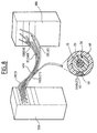
- color-tinted translucent jacketing material or color tinted side-emitting optical fibers in a communication system having numerous optically detectable cables as shown in Fig. 8 promotes the ability to illuminate the side-emitting fibers of multiple cables simultaneously while detecting an individual cable by observing the color of the light emanating from the respective cables.
- Fig. 8 illustrates a generic communication system, for example, two patch panels, including a transmission unit 200, a receiving unit 300, and numerous optically detectable communication cables 400 connected therebetween to accommodate the transmission of communication signals.
- Each of the optically detectable communication cables have side-emitting optical fibers 50, as illustrated by the cross section.
- the illustrated cross section of one of the optically detectable communication cables 400 is similar to the fiber optic communication cable 5 illustrated in Fig 1, but could also be implemented via any of the contemplated cable configurations.
- the side-emitting optical fiber 50 is embedded in translucent jacketing material 45 of the cable jacket 40.
- the translucent jacketing material is designated as having a violet tint.
- optically detectable cables have the same color, for example, clear
- individual cables may be optically distinguished by inputting detecting light into cable ends of the cables to be detect.
- the cable or cables to be detected light up along their respective axes.
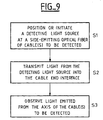
- a method for detecting individual cables of a complex cabling system for example, the communication system of Fig. 8, is illustrated in Fig. 9.
- a light source or detector light is positioned at an interface housing an end of a cable or cables to be detected.
- the cable ends have an adapter or interface to promote connection of the cable ends to different communication or wiring connection ports on the communications system.
- the communication system may have a detecting light source, such as an LED, laser, or incandescent lamp, built in to each of the connection ports so that disconnecting the cable to be detected from its respective connection port is not necessary.
- a detecting light source such as an LED, laser, or incandescent lamp
- the detecting light source transmits light into the interface housing of the respective cables to be detected.
- a user observes light emitted from the side-emitting optical fiber along an axis of the respective cables to be detected.
- a hand-held detecting light may be used.
- This hand-held detection light source may either be adapted to be connected to the cable end interface, or by injecting the detecting light through the side of the cables 400 into the side-emitting optical fiber 50.
- a user is required to manually position the detecting light source at the interface housing an end of a cable or cables to be detected.
- the detecting light transmits light into the cables to be detected, and the user detects individual cables by observing light emitted along their axes.
- the hand-held detecting light may also be an LED, laser, or incandescent light source.
- multiple cables may be illuminated at one time and the cables are detected by the color of light emitted along their respective axes.
- FIG. 10a illustrates a cable forming device 500 for manufacturing the above-described cables.
- an optical fiber is drawn from a fiber payoff roll 510, along with aramid yarns from a plurality of aramid payoffs 530, and a side-emitting optical fiber from side-emitting fiber payoff 550, into a cable forming device.
- the strands of the respective payoffs are pulled through lay plate 560 and cross-head tip and die 565 by a pulling device 567 or capstan.
- a translucent jacketing material 45 is extruded onto the fibers from extruder 540.
- the extruded cable is then pulled through cooling trough 566 and the finished cable is collected on take-up reel 568.
- the aforementioned manufacturing process produces a cable having a side-emitting optical fiber and an entirely translucent cable jacket.
- Fig. 10b shows a modification to the cable forming machine for producing a cable having an opaque outer jacket where only a portion the cable jacket is made of translucent jacketing material 45.
- a second extruder 545 is used with a striping tip to stripe the opaque cable jacket with a translucent portion.
- Dual extruders for striping cables are well known in the art and thus are not explained in significant detail.
- Opaque jacketing materials may have flame retardant fillers, thus this option may serve to provide a more flame-resistant cable having a side-emitting optical fiber than that with an entirely translucent cabling jacket.
- the foregoing manufacturing method using cable manufacturing device 500 is not limited to fiber optic cables, but may be used to produce electrical conductor cables as would be apparent to one of ordinary skill in the art.
- the cable manufacturing device 500 may also be setup to pull more than one optical fiber or electrical conductor into a single cable or form any of the cable-embodiments described above.
- FIG. 11 illustrates an optical fiber ribbon 600 having a plurality of optical fibers 610 disposed inside the optical fiber ribbon 600.
- a side emitting optical fiber 611 is disposed at a location of the ribbon 600 so that the location of the ribbon 600 may be determined, for example, in dense ribbon control panels.
- Another advantage of the side-emitting fiber in the ribbon is that it becomes a position identifier and a point to reference the other optical fibers from, when an operation such as splicing is desired. This allows for the operator or the splicing machine to detect/confirm that the fibers from each ribbon are aligned correctly without the operator having to use individual fiber colors or outer ribbon print markings to indicate the correct match-up.
- Fig. 12 illustrates a hose 620 having a side-emitting optical fiber 621 disposed along the length of the hose 620.
- the hose may be a conduit for air, water, gases, fluids or conductors, in which for example, it is desired to locate the hose at any point along its length in a dense hydraulic control box or panel.
- a hose coupling 622 is disposed on an end of hose 620.
- Hose coupling 622 has a coupling channel 623 for receiving the side-emitting optical fiber 621.
- a light source 624 such as an LED, is positioned in the hose coupling 622 for providing light to the side-emitting optical fiber 621. Power can be provided through a light source connector 625 to illuminate light source 624.
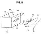
- Fig. 13 illustrates an embodiment where a MT-RJ cable is adapted for a side-emitting optical fiber.
- MT-RJ cables are a common configuration of cables known in the art, thus detailed a description is omitted.
- an MT connector 720 has a light source or switch 721 and a power source 722.
- the connector 720 has a plurality of receiving holes for receiving the cable 700.
- the receiving holes may include optical transmission fiber receiving holes 723 for transmission of data, a side-emitting optical fiber receiving hole 724 for receiving side-emitting optical fiber 705, and a conductor receiving hole 725 for providing power to cable conductor 710.
- Cable jacket has a translucent portion thereof to allow side-emitting optical fiber 705 to be observed therethrough.
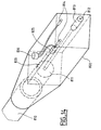
- Fig. 14 illustrates one example of a side-emitting and optical fiber connector 800.
- a cable or conduit 810 has a side-emitting optical fiber 820, and is capped with the connector 800.
- aramid 811 surrounds a communications optical fiber 812 and is adapted for connection to a communications port by an optical fiber precision connector ceramic pin 813.
- Connector 800 also has power source pins 814 which provide power to LED 825. Switch 830, when closed, provides power to LED 825 via power pins 814. In this manner, LED 825 illuminates and end of side-emitting optical fiber 820 for detection purposes.
- Connector 800 is illustrated as a rectangular box to enhance drawing comprehension, but may be any number of shapes as the skilled artisan would recognize. Additionally, the connector 800 is provided only to promote understanding of a potential connection device, and can be adapted in numerous ways as would be apparent to one of ordinary skill.
Landscapes
- Physics & Mathematics (AREA)
- General Physics & Mathematics (AREA)
- Optics & Photonics (AREA)
- Engineering & Computer Science (AREA)
- Manufacturing & Machinery (AREA)
- Light Guides In General And Applications Therefor (AREA)
- Communication Cables (AREA)
Applications Claiming Priority (2)
| Application Number | Priority Date | Filing Date | Title |
|---|---|---|---|
| US09/604,972 US6347172B1 (en) | 2000-06-28 | 2000-06-28 | Cable having side-emitting fiber under transparent or translucent cable jacket |
| US604972 | 2000-06-28 |
Publications (2)
| Publication Number | Publication Date |
|---|---|
| EP1168025A2 true EP1168025A2 (fr) | 2002-01-02 |
| EP1168025A3 EP1168025A3 (fr) | 2002-01-09 |
Family
ID=24421755
Family Applications (1)
| Application Number | Title | Priority Date | Filing Date |
|---|---|---|---|
| EP01401601A Ceased EP1168025A3 (fr) | 2000-06-28 | 2001-06-18 | Câble ayant une fibre à émission latérale sous gaine de câble transparente ou translucide |
Country Status (2)
| Country | Link |
|---|---|
| US (1) | US6347172B1 (fr) |
| EP (1) | EP1168025A3 (fr) |
Cited By (21)
| Publication number | Priority date | Publication date | Assignee | Title |
|---|---|---|---|---|
| EP2345918A1 (fr) * | 2010-01-19 | 2011-07-20 | Nexans | Fibre optique comprenant une couche extérieure apte à émettre une radiation lumineuse visible |
| WO2013122825A1 (fr) * | 2012-02-13 | 2013-08-22 | Corning Cable Systems Llc | Système de traceur visuel destiné à un câble à fibres optiques |
| WO2014200902A1 (fr) * | 2013-06-10 | 2014-12-18 | Corning Optical Communications LLC | Ensemble câble à fibre optique comprenant une fibre de traceur optique |
| WO2015023459A1 (fr) * | 2013-08-12 | 2015-02-19 | Corning Optical Communications LLC | Ensemble câble à fibre optique comportant une fibre à traceur optique |
| US9304278B1 (en) | 2015-03-31 | 2016-04-05 | Corning Optical Communications LLC | Traceable cable with side-emitting optical fiber and method of forming the same |
| WO2016081298A1 (fr) * | 2014-11-18 | 2016-05-26 | Corning Optical Communications LLC | Câble à fibre optique traçable et dispositif d'affichage filtré permettant d'améliorer la traçabilité |
| EP3096077A1 (fr) * | 2015-05-20 | 2016-11-23 | Corning Optical Communications LLC | Câble traçable à fibre optique à émission latérale et son procédé de formation |
| WO2017074670A1 (fr) * | 2015-10-30 | 2017-05-04 | Corning Optical Communications LLC | Ensemble de câble traçable et connecteur |
| EP2557444A4 (fr) * | 2010-04-05 | 2017-06-21 | Fujikura Co., Ltd. | Fil à âme enroulée de fibres optiques, câble à fibres optiques et motif de câblage |
| EP3196893A4 (fr) * | 2014-07-23 | 2017-08-02 | ZTE Corporation | Procédé et dispositif de reconnaissance d'objet |
| EP3211465A4 (fr) * | 2014-10-20 | 2017-11-29 | ZTE Corporation | Ensemble fibre optique composite en matière plastique et quartz, dispositif et procédé de reconnaissance |
| CN107771295A (zh) * | 2015-05-20 | 2018-03-06 | 康宁光电通信有限责任公司 | 具有侧发射光纤的可追踪的电缆和其形成方法 |
| US10107983B2 (en) | 2016-04-29 | 2018-10-23 | Corning Optical Communications LLC | Preferential mode coupling for enhanced traceable patch cord performance |
| US10185111B2 (en) | 2016-04-08 | 2019-01-22 | Corning Optical Communications LLC | Traceable end point cable assembly |
| US10222561B2 (en) | 2016-12-21 | 2019-03-05 | Corning Research & Development Corporation | Light launch device for transmitting light into a traceable fiber optic cable assembly with tracing optical fibers |
| US10228526B2 (en) | 2015-03-31 | 2019-03-12 | Corning Optical Communications LLC | Traceable cable with side-emitting optical fiber and method of forming the same |
| US10234614B2 (en) | 2017-01-20 | 2019-03-19 | Corning Research & Development Corporation | Light source assemblies and systems and methods with mode homogenization |
| US10338317B2 (en) | 2015-07-17 | 2019-07-02 | Corning Optical Communications LLC | Systems and methods for traceable cables |
| US10534135B2 (en) | 2015-07-17 | 2020-01-14 | Corning Optical Communications LLC | Systems and methods for tracing cables and cables for such systems and methods |
| US10539758B2 (en) | 2017-12-05 | 2020-01-21 | Corning Research & Development Corporation | Traceable fiber optic cable assembly with indication of polarity |
| US10539747B2 (en) | 2017-12-05 | 2020-01-21 | Corning Research & Development Corporation | Bend induced light scattering fiber and cable assemblies and method of making |
Families Citing this family (48)
| Publication number | Priority date | Publication date | Assignee | Title |
|---|---|---|---|---|
| GB9820854D0 (en) * | 1998-09-24 | 1998-11-18 | Lifor Limited | Fibre optic based directional way finding apparatus and method |
| US20020131121A1 (en) * | 2001-03-13 | 2002-09-19 | Muthu Jeganathan | Transceiver, system, and method for free-space optical communication and tracking |
| EP1359248B1 (fr) * | 2002-05-02 | 2009-06-03 | Fatzer AG | Cable lumineux |
| US20030210780A1 (en) * | 2002-05-10 | 2003-11-13 | Pratt Steven Duane | Device housing having one or more optical fibers |
| US6823120B2 (en) | 2002-07-31 | 2004-11-23 | Corning Cable Systems Llc | Transmit/receive optical cables |
| US7195561B2 (en) * | 2002-09-24 | 2007-03-27 | Intec, Inc. | Video game controller with illuminated cable |
| US7164819B2 (en) * | 2003-03-10 | 2007-01-16 | Fiberstars, Inc. | Side-light extraction by light pipe-surface alteration and light-extraction devices extending radially beyond the outer cladding |
| US20040223691A1 (en) * | 2003-03-10 | 2004-11-11 | Buelow Roger F. | Light pipe with directional side-light extraction |
| US7020369B2 (en) * | 2004-07-08 | 2006-03-28 | Berwick Offray Llc | Ribbon with fiber optics |
| SE528408C2 (sv) * | 2005-03-07 | 2006-11-07 | Interactive Inst Ii Ab | En metod och en anordning för visuell indikering av ström- eller effektförbrukning i en elkabel |
| US7329857B1 (en) | 2006-03-01 | 2008-02-12 | Sandia Corporation | Side-emitting fiber optic position sensor |
| CN102077125B (zh) * | 2008-05-28 | 2014-07-02 | Adc电信公司 | 光缆 |
| AU2009320044B2 (en) | 2008-10-28 | 2014-11-13 | Adc Telecommunications, Inc. | Flat drop cable |
| WO2011050181A2 (fr) | 2009-10-21 | 2011-04-28 | Adc Telecommunications, Inc. | Branchement d'abonné plat muni d'un élément de résistance central |
| US8475083B2 (en) * | 2010-03-31 | 2013-07-02 | University Court Of The University Of St. Andrews | Umbilical for underwater diving |
| US8915659B2 (en) | 2010-05-14 | 2014-12-23 | Adc Telecommunications, Inc. | Splice enclosure arrangement for fiber optic cables |
| WO2011146720A2 (fr) | 2010-05-19 | 2011-11-24 | Adc Telecommunications, Inc. | Câble de dérivation plat avec protubérance centrale |
| US8322871B1 (en) * | 2010-05-26 | 2012-12-04 | Telect, Inc. | Optical fiber tracing system |
| US8885998B2 (en) | 2010-12-09 | 2014-11-11 | Adc Telecommunications, Inc. | Splice enclosure arrangement for fiber optic cables |
| US9739966B2 (en) | 2011-02-14 | 2017-08-22 | Commscope Technologies Llc | Fiber optic cable with electrical conductors |
| ES2787826T3 (es) | 2011-04-28 | 2020-10-19 | L E S S Ltd | Aparatos de guía de ondas para sistemas de iluminación |
| US8781281B2 (en) | 2011-07-21 | 2014-07-15 | Adc Telecommunications, Inc. | Drop cable with angled reinforcing member configurations |
| US8805141B2 (en) | 2011-10-07 | 2014-08-12 | Corning Incorporated | Optical fiber illumination systems and methods |
| WO2013155366A1 (fr) | 2012-04-13 | 2013-10-17 | Orthoaccel Technologies, Inc. | Dispositifs orthodontiques laser |
| WO2013188973A1 (fr) * | 2012-06-18 | 2013-12-27 | Universite Laval | Sonde optogénétique |
| US9316802B2 (en) | 2012-08-24 | 2016-04-19 | Commscope Technologies Llc | Optical fiber cable having reinforcing layer of tape heat-bonded to jacket |
| AU2014275486B2 (en) | 2013-03-18 | 2017-07-27 | Commscope Technologies Llc | Architecture for a wireless network |
| US9557505B2 (en) | 2013-03-18 | 2017-01-31 | Commscope Technologies Llc | Power and optical fiber interface |
| KR20160010496A (ko) | 2013-05-14 | 2016-01-27 | 에이디씨 텔레커뮤니케이션스 인코포레이티드 | 전력/광섬유 복합 케이블 |
| US9715076B2 (en) * | 2013-07-29 | 2017-07-25 | Prysmian S.P.A. | Optical cable for terrestrial networks |
| US9213134B2 (en) * | 2013-08-06 | 2015-12-15 | Verizon Patent And Licensing Inc. | Alignment for splicing multi-core optical fibers |
| ES2864634T3 (es) | 2013-10-18 | 2021-10-14 | L E S S Ltd | Aparato de iluminación basado en guía de ondas |
| EP2871708B1 (fr) * | 2013-11-07 | 2021-06-16 | Swisscom AG | Câble de communication avec éclairage |
| CN105445872B (zh) * | 2014-05-30 | 2018-12-07 | 徕心光电股份有限公司 | 光学缆线模块 |
| CN105182484B (zh) * | 2014-05-30 | 2018-09-25 | 徕心光电股份有限公司 | 光学缆线模块及其制造方法 |
| CN106660082B (zh) | 2014-06-30 | 2023-09-22 | 皇家飞利浦有限公司 | 防生物结垢的系统 |
| US9857515B2 (en) | 2014-07-28 | 2018-01-02 | Corning Incorporated | Side-emitting optical fiber system and assembly with light-emitting jacket members |
| KR102561246B1 (ko) * | 2014-12-16 | 2023-07-31 | 코닌클리케 필립스 엔.브이. | 부착 방지를 위해 적응된 해저 케이블 장치 |
| WO2016141196A1 (fr) * | 2015-03-04 | 2016-09-09 | Commscope Technologies Llc | Système de conduit hybride |
| JP6627486B2 (ja) * | 2015-12-18 | 2020-01-08 | 日立金属株式会社 | 光ファイバケーブル及び光ファイバケーブルの識別方法 |
| US10793449B2 (en) | 2016-04-27 | 2020-10-06 | Arizona Board Of Regents On Behalf Of Arizona State University | Fiber-optic integrated membrane reactor |
| US10036867B2 (en) * | 2016-08-31 | 2018-07-31 | International Business Machines Corporation | Illuminating cable for enhanced traceability |
| EP3539255A4 (fr) | 2016-11-09 | 2020-05-27 | Commscope Inc. of North Carolina | Module d'infrastructure alimenté échangeable |
| CN108022690A (zh) * | 2017-12-06 | 2018-05-11 | 山东太平洋光纤光缆有限公司 | 一种管带敷设用光电复合缆及制造方法 |
| US11754778B2 (en) | 2018-11-21 | 2023-09-12 | Arizona Board Of Regents On Behalf Of Arizona State University | Photoresponsive polymer coated optical fibers for water treatment |
| CN110850539B (zh) * | 2019-11-15 | 2021-03-16 | 烽火通信科技股份有限公司 | 一种基于光信号的识别光缆及其制备方法 |
| US12029826B2 (en) | 2021-02-08 | 2024-07-09 | Arizona Board Of Regents On Behalf Of Arizona State University | UV-C wavelength side-emitting optical fibers |
| JP7618047B2 (ja) * | 2021-09-09 | 2025-01-20 | 京セラ株式会社 | 発光装置 |
Family Cites Families (11)
| Publication number | Priority date | Publication date | Assignee | Title |
|---|---|---|---|---|
| DE69333369T2 (de) | 1992-05-01 | 2004-10-07 | Sumitomo Electric Industries | Verfahren zur Identifikation einer optischen Leitung |
| US5617497A (en) * | 1993-05-21 | 1997-04-01 | Super Vision International, Inc. | Lateral illumination fiber optic cable device and method of manufacture |
| US5577147A (en) | 1994-03-31 | 1996-11-19 | Lucent Technologies Inc. | Magnetically locatable optical fiber cables containing integrated magnetic marker materials |
| IL113674A (en) | 1995-05-09 | 1998-06-15 | Laser Ind Ltd | Side-emitting optical fibers for lasers with orientation markings |
| AU715687B2 (en) * | 1996-01-19 | 2000-02-10 | Lumenyte International Corporation | Side lighting optical conduit |
| US5708499A (en) | 1996-07-24 | 1998-01-13 | Lucent Technologies Inc. | Optical components for live-fiber identifier and coupler |
| US5995702A (en) * | 1997-04-08 | 1999-11-30 | Roblon A/S | Side radiating cable with increased light output |
| US5905837A (en) | 1997-07-22 | 1999-05-18 | Nec Usa, Inc. | Side emitting optical fiber |
| US5982967A (en) * | 1997-12-12 | 1999-11-09 | Lucent Technologies Inc. | Color-coded optical fiber cable and a method for manufacturing the same |
| EP0939274A3 (fr) * | 1998-02-25 | 2000-05-24 | Koninklijke Philips Electronics N.V. | Càble à fibres optiques à diffusion latérale de lumière |
| US6275644B1 (en) * | 1998-12-15 | 2001-08-14 | Transmatic, Inc. | Light fixture including light pipe having contoured cross-section |
-
2000
- 2000-06-28 US US09/604,972 patent/US6347172B1/en not_active Expired - Fee Related
-
2001
- 2001-06-18 EP EP01401601A patent/EP1168025A3/fr not_active Ceased
Cited By (33)
| Publication number | Priority date | Publication date | Assignee | Title |
|---|---|---|---|---|
| FR2955399A1 (fr) * | 2010-01-19 | 2011-07-22 | Nexans | Fibre optique comprenant une couche exterieure apte a emettre une radiation lumineuse visible |
| EP2345918A1 (fr) * | 2010-01-19 | 2011-07-20 | Nexans | Fibre optique comprenant une couche extérieure apte à émettre une radiation lumineuse visible |
| EP2557444A4 (fr) * | 2010-04-05 | 2017-06-21 | Fujikura Co., Ltd. | Fil à âme enroulée de fibres optiques, câble à fibres optiques et motif de câblage |
| US9671551B2 (en) | 2012-02-13 | 2017-06-06 | Corning Optical Communications LLC | Visual tracer system for fiber optic cable |
| CN104169771B (zh) * | 2012-02-13 | 2018-05-29 | 康宁光电通信有限责任公司 | 用于光缆的视觉跟踪仪系统 |
| WO2013122825A1 (fr) * | 2012-02-13 | 2013-08-22 | Corning Cable Systems Llc | Système de traceur visuel destiné à un câble à fibres optiques |
| CN104169771A (zh) * | 2012-02-13 | 2014-11-26 | 康宁光电通信有限责任公司 | 用于光缆的视觉跟踪仪系统 |
| US8620123B2 (en) | 2012-02-13 | 2013-12-31 | Corning Cable Systems Llc | Visual tracer system for fiber optic cable |
| WO2014200902A1 (fr) * | 2013-06-10 | 2014-12-18 | Corning Optical Communications LLC | Ensemble câble à fibre optique comprenant une fibre de traceur optique |
| WO2015023459A1 (fr) * | 2013-08-12 | 2015-02-19 | Corning Optical Communications LLC | Ensemble câble à fibre optique comportant une fibre à traceur optique |
| US9429731B2 (en) | 2013-08-12 | 2016-08-30 | Corning Optical Communications LLC | Optical fiber cable assembly comprising optical tracer fiber |
| EP3196893A4 (fr) * | 2014-07-23 | 2017-08-02 | ZTE Corporation | Procédé et dispositif de reconnaissance d'objet |
| EP3211465A4 (fr) * | 2014-10-20 | 2017-11-29 | ZTE Corporation | Ensemble fibre optique composite en matière plastique et quartz, dispositif et procédé de reconnaissance |
| US10107974B2 (en) | 2014-10-20 | 2018-10-23 | Zte Corporation | Quartz plastic composite optical fiber assembly, recognition method and device |
| US10379309B2 (en) | 2014-11-18 | 2019-08-13 | Corning Optical Communications LLC | Traceable optical fiber cable and filtered viewing device for enhanced traceability |
| WO2016081298A1 (fr) * | 2014-11-18 | 2016-05-26 | Corning Optical Communications LLC | Câble à fibre optique traçable et dispositif d'affichage filtré permettant d'améliorer la traçabilité |
| US10228526B2 (en) | 2015-03-31 | 2019-03-12 | Corning Optical Communications LLC | Traceable cable with side-emitting optical fiber and method of forming the same |
| US9304278B1 (en) | 2015-03-31 | 2016-04-05 | Corning Optical Communications LLC | Traceable cable with side-emitting optical fiber and method of forming the same |
| CN107771295A (zh) * | 2015-05-20 | 2018-03-06 | 康宁光电通信有限责任公司 | 具有侧发射光纤的可追踪的电缆和其形成方法 |
| US10101553B2 (en) | 2015-05-20 | 2018-10-16 | Corning Optical Communications LLC | Traceable cable with side-emitting optical fiber and method of forming the same |
| EP3096077A1 (fr) * | 2015-05-20 | 2016-11-23 | Corning Optical Communications LLC | Câble traçable à fibre optique à émission latérale et son procédé de formation |
| US10534135B2 (en) | 2015-07-17 | 2020-01-14 | Corning Optical Communications LLC | Systems and methods for tracing cables and cables for such systems and methods |
| US10338317B2 (en) | 2015-07-17 | 2019-07-02 | Corning Optical Communications LLC | Systems and methods for traceable cables |
| WO2017074670A1 (fr) * | 2015-10-30 | 2017-05-04 | Corning Optical Communications LLC | Ensemble de câble traçable et connecteur |
| US10101545B2 (en) | 2015-10-30 | 2018-10-16 | Corning Optical Communications LLC | Traceable cable assembly and connector |
| US10185111B2 (en) | 2016-04-08 | 2019-01-22 | Corning Optical Communications LLC | Traceable end point cable assembly |
| US10107983B2 (en) | 2016-04-29 | 2018-10-23 | Corning Optical Communications LLC | Preferential mode coupling for enhanced traceable patch cord performance |
| US10222560B2 (en) | 2016-12-21 | 2019-03-05 | Corning Research & Development Corporation | Traceable fiber optic cable assembly with fiber guide and tracing optical fibers for carrying light received from a light launch device |
| US10222561B2 (en) | 2016-12-21 | 2019-03-05 | Corning Research & Development Corporation | Light launch device for transmitting light into a traceable fiber optic cable assembly with tracing optical fibers |
| US10545298B2 (en) | 2016-12-21 | 2020-01-28 | Corning Research & Development Corporation | Traceable fiber optic cable assembly with illumination structure and tracing optical fibers for carrying light received from a light launch device |
| US10234614B2 (en) | 2017-01-20 | 2019-03-19 | Corning Research & Development Corporation | Light source assemblies and systems and methods with mode homogenization |
| US10539758B2 (en) | 2017-12-05 | 2020-01-21 | Corning Research & Development Corporation | Traceable fiber optic cable assembly with indication of polarity |
| US10539747B2 (en) | 2017-12-05 | 2020-01-21 | Corning Research & Development Corporation | Bend induced light scattering fiber and cable assemblies and method of making |
Also Published As
| Publication number | Publication date |
|---|---|
| EP1168025A3 (fr) | 2002-01-09 |
| US6347172B1 (en) | 2002-02-12 |
Similar Documents
| Publication | Publication Date | Title |
|---|---|---|
| US6347172B1 (en) | Cable having side-emitting fiber under transparent or translucent cable jacket | |
| US9671551B2 (en) | Visual tracer system for fiber optic cable | |
| US5463706A (en) | Light traceable transmission conduit assembly | |
| US5666453A (en) | Fiber optic jumper cables and tracing method using same | |
| WO2005106899A1 (fr) | Cable de transmission optiquement traçable pour la transmission de donnees ou d'electricite et conduit traçable | |
| US20180172925A1 (en) | Traceable end point cable assembly having a tracing waveguide | |
| US9690061B2 (en) | Multifiber subunit cable | |
| US9176295B2 (en) | Stranded optical cable with connectors | |
| WO2008048955A2 (fr) | Cordon de connexion avec un conduit de lumière | |
| US20050052174A1 (en) | Traceable patch cable and connector assembly and method for identifying patch cable ends | |
| WO2014035022A1 (fr) | Épisseur par fusion ayant une fonction supplémentaire de contrôle des fibres optiques | |
| CN216749443U (zh) | 多芯易分离室内布线用光电混合缆 | |
| CN114063231B (zh) | 一种可识别纤芯的光纤配线盘及短距离通信系统 | |
| EP3211465B1 (fr) | Ensemble fibre optique composite en matière plastique et quartz, dispositif et procédé de reconnaissance | |
| KR102068185B1 (ko) | 광섬유 케이블을 포함하는 케이블 구조 | |
| KR100516822B1 (ko) | 광점퍼코드 | |
| JP2019066889A (ja) | 光ファイバケーブル | |
| KR20200010885A (ko) | 광전복합 케이블 및 이를 구비하는 광전복합 점퍼 코드 | |
| US20090087152A1 (en) | Optical Cable, Arrangement for Connecting a Multiplicity of Optical Waveguides, and Method for Manufacturing an Optical Cable | |
| CN109357844B (zh) | 一种可见光快速寻线系统 | |
| KR100576152B1 (ko) | 광신호검출장치 | |
| JP6533254B2 (ja) | 光ファイバケーブル | |
| CN221101103U (zh) | 一种光电端头识别的光纤跳线 | |
| KR100320369B1 (ko) | 다심광점퍼코드 | |
| CN210427866U (zh) | 光纤活动连接器 |
Legal Events
| Date | Code | Title | Description |
|---|---|---|---|
| PUAI | Public reference made under article 153(3) epc to a published international application that has entered the european phase |
Free format text: ORIGINAL CODE: 0009012 |
|
| PUAL | Search report despatched |
Free format text: ORIGINAL CODE: 0009013 |
|
| AK | Designated contracting states |
Kind code of ref document: A2 Designated state(s): AT BE CH CY DE DK ES FI FR GB GR IE IT LI LU MC NL PT SE TR |
|
| AX | Request for extension of the european patent |
Free format text: AL;LT;LV;MK;RO;SI |
|
| AK | Designated contracting states |
Kind code of ref document: A3 Designated state(s): AT BE CH CY DE DK ES FI FR GB GR IE IT LI LU MC NL PT SE TR |
|
| AX | Request for extension of the european patent |
Free format text: AL;LT;LV;MK;RO;SI |
|
| 17P | Request for examination filed |
Effective date: 20020709 |
|
| AKX | Designation fees paid |
Free format text: AT BE CH CY DE DK ES FI FR GB GR IE IT LI LU MC NL PT SE TR |
|
| 17Q | First examination report despatched |
Effective date: 20081128 |
|
| STAA | Information on the status of an ep patent application or granted ep patent |
Free format text: STATUS: THE APPLICATION HAS BEEN REFUSED |
|
| 18R | Application refused |
Effective date: 20100701 |