EP1168139A2 - Sytème d'ordinateur - Google Patents
Sytème d'ordinateur Download PDFInfo
- Publication number
- EP1168139A2 EP1168139A2 EP01302523A EP01302523A EP1168139A2 EP 1168139 A2 EP1168139 A2 EP 1168139A2 EP 01302523 A EP01302523 A EP 01302523A EP 01302523 A EP01302523 A EP 01302523A EP 1168139 A2 EP1168139 A2 EP 1168139A2
- Authority
- EP
- European Patent Office
- Prior art keywords
- segments
- shaft
- seal
- springs
- force
- Prior art date
- Legal status (The legal status is an assumption and is not a legal conclusion. Google has not performed a legal analysis and makes no representation as to the accuracy of the status listed.)
- Withdrawn
Links
Images


Classifications
-
- G—PHYSICS
- G06—COMPUTING OR CALCULATING; COUNTING
- G06F—ELECTRIC DIGITAL DATA PROCESSING
- G06F21/00—Security arrangements for protecting computers, components thereof, programs or data against unauthorised activity
- G06F21/60—Protecting data
- G06F21/62—Protecting access to data via a platform, e.g. using keys or access control rules
- G06F21/6218—Protecting access to data via a platform, e.g. using keys or access control rules to a system of files or objects, e.g. local or distributed file system or database
-
- G—PHYSICS
- G11—INFORMATION STORAGE
- G11B—INFORMATION STORAGE BASED ON RELATIVE MOVEMENT BETWEEN RECORD CARRIER AND TRANSDUCER
- G11B20/00—Signal processing not specific to the method of recording or reproducing; Circuits therefor
- G11B20/00086—Circuits for prevention of unauthorised reproduction or copying, e.g. piracy
-
- G—PHYSICS
- G11—INFORMATION STORAGE
- G11B—INFORMATION STORAGE BASED ON RELATIVE MOVEMENT BETWEEN RECORD CARRIER AND TRANSDUCER
- G11B20/00—Signal processing not specific to the method of recording or reproducing; Circuits therefor
- G11B20/00086—Circuits for prevention of unauthorised reproduction or copying, e.g. piracy
- G11B20/00855—Circuits for prevention of unauthorised reproduction or copying, e.g. piracy involving a step of exchanging information with a remote server
-
- G—PHYSICS
- G11—INFORMATION STORAGE
- G11B—INFORMATION STORAGE BASED ON RELATIVE MOVEMENT BETWEEN RECORD CARRIER AND TRANSDUCER
- G11B7/00—Recording or reproducing by optical means, e.g. recording using a thermal beam of optical radiation by modifying optical properties or the physical structure, reproducing using an optical beam at lower power by sensing optical properties; Record carriers therefor
Definitions
- the present invention relates to seals employed in elastic fluid axial flow turbines and, more particularly, to segmented packing ring seals arranged both where rotatable shafts penetrate stationary turbine casings and, in addition, internal to the casings between stages and turbine sections.
- such known seals prevent or reduce leakage of the fluid by creating small clearance areas with low flow coefficients between the rotating and stationary parts. Improved efficiency, minimized loss of fluid and prevention of undesirable side effects caused by leakage of fluid are objectives of such seals.
- these packing rings must employ relatively strong back springs that support the segments and simultaneously force them toward the shaft, yet during periods of shaft misalignment when the packing is rubbing the shaft, allow the segments to yield. Because of the relatively high spring force, the rubbing contact of shaft and packing teeth generates significant amounts of heat in the shaft, leading to bowing, rubbed packing teeth and tip seals, vibration and aborted start-ups. The thermodynamic losses are significant.
- the heat generated during such events is proportional to the spring force that resists the temporary motion of the packing segment when the teeth are in contact with the rotating shaft. It is thus desirable to minimize the spring force selected to keep the segments in the closed position. It is expected that this will usually reduce heat generation to less than one-hundredth that experienced in original designs.
- a double flow entry nozzle In some intermediate pressure turbine sections and almost all low-pressure turbine sections, a double flow entry nozzle is provided. This nozzle needs a packing ring to prevent leakage along the shaft from one end of the nozzle to the other. This is due to the fact that the pressure never turns out to be exactly the same at both sides. Leakage effects can be serious since a 1% leak will cause a 1% stage loss at each end of the nozzle.
- a segmented seal ring and spring system for steam turbines for minimizing leakage between rotating and stationary components including a segmented seal ring being supported by and at least partially contained in an annular T-shaped or L-shaped groove formed in the turbine casing and extending circumferentially around the turbine shaft.
- the spring system includes springs positioned to be biased against the segments of the seal ring to urge the segments radially inwardly toward a small clearance position of the seal ring with respect to the turbine shaft, yet with the use of minimum force.
- the individual strengths of the springs are selected depending on the circumferential positions of the seal segments, the fluid pressure forces, and the weight and friction forces to thereby assure that the seal ring segments are in the small clearance position at all times except when misalignment and contact with the shaft causes one or more segments to be shifted from that position.
- a special gravity or levitation spring is provided in the lowest, lower half seal ring segments with the lower end of such spring in contact with the turbine casing while the upper spring end is biased against the seal segment to produce an upward force on the segments to counter the downward force caused by the weight of the segments.
- the gravity springs have a spring force in the vertical direction, which is approximately equal to the weight of the segment which it supports, so that during shaft rubs, the force required by the shaft to shift the seal segment outward is minimized. When the rubbing period is over, the springs can assure return of the segment to the normal closed position.
- top segments are supported by keys bolted to the horizontal joint of the backing holders, but pins can be used instead.
- the upper segments will require inward forcing springs at the bottom of the segments with enough force to overcome sliding friction plus the horizontal outward force of the butt spring located between the top two segments.
- the friction can be reduced by the addition of butt-mounted coil springs under the segment with force approximately equal to the weight of all segments, which are supported by the spring.
- the upper held segments benefit from being isolated from the lower segments and supported from the horizontal joints.
- the lower segments can be further assisted in closing to the small clearance position at the side locations by the addition of springs pushing the segments radially inwardly near the horizontal joints.
- the turbine includes a rotor, a portion of which is shown at 11, and a casing, a portion of which is shown at 12.
- part 12 the casing
- the casing could instead be called a diaphragm.
- Only one seal ring 13 is illustrated, although several such rings could be arranged in series.
- the seal ring shown is typical of many found throughout the turbine.
- the seal ring 13 includes a plurality of teeth 14 that are disposed in opposition to circumferential portions of the shaft which are alternately stepped up and down in radius. With high pressure fluid at 18 and low pressure at 19 there will be a positive force to cause fluid leakage between the multiple restrictions formed by the small openings between the teeth 14 and the shaft 11.
- the combination of the clearance area, the relative relative sharpness of the teeth, the number of the restrictions, the fluid conditions including pressure and density, and the geometry of the leakage path determine the amount of leakage flow according to formulae and empirical constants which are well known. Many other geometrical arrangements are also used to provide multiple or single leakage restrictions than the style illustrated.
- seal ring is retained in annular groove 15 of the casing 12.
- the seal ring is comprised of four segments each disposed within the groove 15 to accommodate assembly or disassembly of the casing by locating the seal ring segments to separate at the joint 27 of the casing. It is to be understood that while the words "seal ring 13" are used herein, they may apply to an individual seal ring segment and, therefore, should be read in the context of the sentence.
- Each segment of the seal ring 13 is shown including the inner ring portion, indicated in Fig. 1 by numeral 13d, having the seal teeth 14 extending from its radially inward surface while its radially outward surface 20a limits the large clearance position by means of its contact with the radial surface 21a of the casing 12.
- the seal ring 13 also includes an outer ring portion 13a disposed within the casing groove 15 with an inner circumferential surface 13b which, as described below, limits the small clearance position of the seal ring segments by restraining their radial inward movement by contact of surface 13b with surface 17 on the shoulder 12a of casing 12.
- seal ring neck portion 13c provides a contact pressure surface which, as shown at 12b, is in direct contact with the casing shoulder 12a.
- the springs are selected with sufficient strength and dimension under these conditions to cause the seal ring segments to be held in the minimum clearance position.
- Fig. 1 the seal ring 13 is shown in its small clearance condition.
- the higher pressure side of the seal is identified at 18. This pressure persists in the annular spaces 24 and 15 as a result of an open communication created by one or more local openings 23a.
- the low pressure condition 19 persists also in the annular space 25.
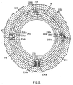
- Fig. 2 shows the improved segmented packing system using four 90° segments 213 with gravity springs 236a and 236b contained in bores 235 in the bottom of each of the lower two 90° segments 213 that are provided to counter the weight plus a small safety factor of the two separate bottom segments when the segments are in the minimum clearance position.
- side helper springs 216a and 216b are provided to urge the lower end of the upper segments 213 to the minimum clearance position by overcoming the friction against motion of the seal segments supported by keeper keys 244.
- a spring 217 is located in a bore 258 where the two top segments meet. This spring provides almost enough force to separate the two segments so as to minimize opening forces required during shaft rubbing conditions.
- Two springs 236 located in bottom segments 213 are provided to elevate the bottom segments to their minimum clearance position.
- the forces provided by springs 236 should each be approximately equal to the weight of one segment 213. This insures that segment 213 will be held in the minimum clearance position, yet capable of radial downward motion with only a small force against the rotor 11.
- anti-rotation keys 244 which are provided above casing joint 27.
- Each anti-rotation key includes a rectangular key block fitted in grooves in the left and right sides of casing 12. The key blocks protrude out from casing 12 into spaces where such key blocks provide a fixed horizontal and circumferential support surface for the upper segments of seal ring 213.
- Anti-rotation keys 244 are secured to casing 12 by mounting screws or bolts attached at the left and right sides to key slots by threaded screw ends extending into the grooves provided in casing 12.
- Coil springs are shown in the drawings; but flat, L-shaped springs can be employed in locations 216a, 216b, 254a, 254b, 236a and 236b.
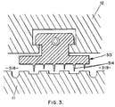
- Fig. 3 is a cross sectional drawing of a modified packing ring 313.
- the closing pressure forces are very large, the force required from the shaft during temporary periods of misalignment and rubbing will be very large and the heat generated will also be very large.
- This condition can be improved by removing one or more teeth 314 from the inlet side 318 of the packing.
- Fig. 3 illustrates this modification, where one tooth on the inlet side has been removed from a ring that is otherwise the same as that shown in Fig. 1.
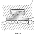
- a similar improvement could be accomplished by adding a tooth 414 to the discharge side 419 as shown in the modified packing ring 413 of Fig. 3A.
- Fig. 4 shows a design provided to accomplish this condition regardless of the flow direction.
- the flow is shown to be traveling from left to right or from 618 to 619. It can enter a space 615 above a packing ring 613 by passing through slots 661 and 662 in the segment hooks at surface 613k, causing space 615 to become pressurized. Flow is discouraged from passing through the corresponding slots by the tight contact of the segment 613 with the casing at 612b.
- the inner surfaces of the slots should be in line with the outer surfaces of the segment neck 613c.
- the packing or seal rings which are the subject of this invention can be applied to any turbine packing ring location.
- the minimum clearance position is attained whenever the seal ring is restrained by contact of seal ring surface 13 with casing surface 17, as shown in Fig. 1, or when the inner edges of seal teeth 14 are in contact with shaft or rotor 11.
- the spring could be a coil type, or a flat L-shaped spring as has been used in conventional packing segments for many decades.
Landscapes
- Engineering & Computer Science (AREA)
- Computer Security & Cryptography (AREA)
- Signal Processing (AREA)
- Theoretical Computer Science (AREA)
- Health & Medical Sciences (AREA)
- Bioethics (AREA)
- General Health & Medical Sciences (AREA)
- Computer Hardware Design (AREA)
- Software Systems (AREA)
- Physics & Mathematics (AREA)
- General Engineering & Computer Science (AREA)
- General Physics & Mathematics (AREA)
- Databases & Information Systems (AREA)
- Signal Processing For Digital Recording And Reproducing (AREA)
- Storage Device Security (AREA)
- Data Exchanges In Wide-Area Networks (AREA)
- Turbine Rotor Nozzle Sealing (AREA)
Applications Claiming Priority (2)
| Application Number | Priority Date | Filing Date | Title |
|---|---|---|---|
| JP2000197085A JP2002014908A (ja) | 2000-06-29 | 2000-06-29 | コンピュータシステム |
| JP2000197085 | 2000-06-29 |
Publications (3)
| Publication Number | Publication Date |
|---|---|
| EP1168139A2 true EP1168139A2 (fr) | 2002-01-02 |
| EP1168139A9 EP1168139A9 (fr) | 2002-05-08 |
| EP1168139A3 EP1168139A3 (fr) | 2004-07-07 |
Family
ID=18695467
Family Applications (1)
| Application Number | Title | Priority Date | Filing Date |
|---|---|---|---|
| EP20010302523 Withdrawn EP1168139A3 (fr) | 2000-06-29 | 2001-03-16 | Sytème d'ordinateur |
Country Status (3)
| Country | Link |
|---|---|
| US (1) | US20020002619A1 (fr) |
| EP (1) | EP1168139A3 (fr) |
| JP (1) | JP2002014908A (fr) |
Family Cites Families (7)
| Publication number | Priority date | Publication date | Assignee | Title |
|---|---|---|---|---|
| US6192407B1 (en) * | 1996-10-24 | 2001-02-20 | Tumbleweed Communications Corp. | Private, trackable URLs for directed document delivery |
| US6199104B1 (en) * | 1997-04-28 | 2001-03-06 | Sabre Inc. | Server-based host monitor |
| US6073172A (en) * | 1997-07-14 | 2000-06-06 | Freegate Corporation | Initializing and reconfiguring a secure network interface |
| WO1999055055A1 (fr) * | 1998-04-17 | 1999-10-28 | Iomega Corporation | Systeme de cle de donnees electroniques protegees sur un support particulier de maniere a empecher une reproduction illicite |
| AU6401999A (en) * | 1998-09-28 | 2000-04-17 | Argus Systems Group, Inc. | Trusted compartmentalized computer operating system |
| US6453354B1 (en) * | 1999-03-03 | 2002-09-17 | Emc Corporation | File server system using connection-oriented protocol and sharing data sets among data movers |
| JP2000276457A (ja) * | 1999-03-25 | 2000-10-06 | Mitsubishi Electric Corp | データ共有コンピュータシステム及びクライアント |
-
2000
- 2000-06-29 JP JP2000197085A patent/JP2002014908A/ja active Pending
-
2001
- 2001-03-16 EP EP20010302523 patent/EP1168139A3/fr not_active Withdrawn
- 2001-03-16 US US09/809,102 patent/US20020002619A1/en not_active Abandoned
Also Published As
| Publication number | Publication date |
|---|---|
| EP1168139A9 (fr) | 2002-05-08 |
| US20020002619A1 (en) | 2002-01-03 |
| JP2002014908A (ja) | 2002-01-18 |
| EP1168139A3 (fr) | 2004-07-07 |
Similar Documents
| Publication | Publication Date | Title |
|---|---|---|
| US5810365A (en) | Retractable segmented packing rings for fluid turbines | |
| EP0638153B1 (fr) | Turbine a fluide elastique employant un anneau d'etancheite segmente | |
| US6220603B1 (en) | Non retractable segmented packing ring for fluid turbines having special springs to reduce forces during shaft rubbing | |
| US4436311A (en) | Segmented labyrinth-type shaft sealing system for fluid turbines | |
| US7344357B2 (en) | Methods and apparatus for assembling a rotary machine | |
| US5080556A (en) | Thermal seal for a gas turbine spacer disc | |
| US5934684A (en) | Retractable segmented packing ring for fluid turbines having gravity springs to neutralize packing segment weight forces | |
| US4017088A (en) | Shaft seal for turbomachines | |
| US6431555B1 (en) | Leaf seal for inner and outer casings of a turbine | |
| RU2478799C2 (ru) | Уплотнение пути прохода пара в паровой турбине, приводимое в действие давлением | |
| EP1384856B1 (fr) | Etanchéification de la fente entre les surfaces terminales des segments de garniture d'étanchéité de turbine à vapeur et rétrofit des segments correspondants | |
| US20040007823A1 (en) | Seal for a rotating member | |
| US12624644B2 (en) | Seal assembly for a rotary machine | |
| US6651986B2 (en) | Retractable packing ring lower half segment retaining key and method for retaining retractable packing ring lower half segment | |
| US11287043B2 (en) | High clearance seal assembly | |
| EP1243755A1 (fr) | Turbine à fluide élastique employant un anneau d'étanchéité | |
| US20070296159A1 (en) | Variable clearance packing ring | |
| CA2572086A1 (fr) | Machines rotary et methodes d'assemblage | |
| KR20030057409A (ko) | 가스 터빈 | |
| JP2002266605A (ja) | シャフト摩擦の間の力を減少させるための特別のバネを持つ流体タービン用の非伸縮式の分割されたパッキングリング | |
| EP0173684B1 (fr) | Systeme d'etancheite d'arbres de type a labyrinthe segmente pour turbines hydrauliques | |
| EP3990808A1 (fr) | Ensemble joint sans contact doté d'éléments d'amortissement | |
| US7540708B2 (en) | Methods and apparatus to facilitate sealing in a turbine | |
| RU2050493C1 (ru) | Лабиринтное уплотнение турбомашины | |
| Schroder et al. | Leaf seal for inner and outer casings of a turbine |
Legal Events
| Date | Code | Title | Description |
|---|---|---|---|
| PUAI | Public reference made under article 153(3) epc to a published international application that has entered the european phase |
Free format text: ORIGINAL CODE: 0009012 |
|
| AK | Designated contracting states |
Kind code of ref document: A2 Designated state(s): AT BE CH CY DE DK ES FI FR GB GR IE IT LI LU MC NL PT SE TR |
|
| AX | Request for extension of the european patent |
Free format text: AL;LT;LV;MK;RO;SI |
|
| PUAL | Search report despatched |
Free format text: ORIGINAL CODE: 0009013 |
|
| AK | Designated contracting states |
Kind code of ref document: A3 Designated state(s): AT BE CH CY DE DK ES FI FR GB GR IE IT LI LU MC NL PT SE TR |
|
| AX | Request for extension of the european patent |
Extension state: AL LT LV MK RO SI |
|
| AKX | Designation fees paid |
Designated state(s): DE FR GB |
|
| STAA | Information on the status of an ep patent application or granted ep patent |
Free format text: STATUS: THE APPLICATION IS DEEMED TO BE WITHDRAWN |
|
| 18D | Application deemed to be withdrawn |
Effective date: 20050108 |