EP1168228A2 - Verbinder für elektronische Karte - Google Patents
Verbinder für elektronische Karte Download PDFInfo
- Publication number
- EP1168228A2 EP1168228A2 EP01114843A EP01114843A EP1168228A2 EP 1168228 A2 EP1168228 A2 EP 1168228A2 EP 01114843 A EP01114843 A EP 01114843A EP 01114843 A EP01114843 A EP 01114843A EP 1168228 A2 EP1168228 A2 EP 1168228A2
- Authority
- EP
- European Patent Office
- Prior art keywords
- disconnectible
- card
- memory storage
- housing assembly
- connection chamber
- Prior art date
- Legal status (The legal status is an assumption and is not a legal conclusion. Google has not performed a legal analysis and makes no representation as to the accuracy of the status listed.)
- Withdrawn
Links
Images


Classifications
-
- G—PHYSICS
- G06—COMPUTING OR CALCULATING; COUNTING
- G06K—GRAPHICAL DATA READING; PRESENTATION OF DATA; RECORD CARRIERS; HANDLING RECORD CARRIERS
- G06K7/00—Methods or arrangements for sensing record carriers, e.g. for reading patterns
- G06K7/0013—Methods or arrangements for sensing record carriers, e.g. for reading patterns by galvanic contacts, e.g. card connectors for ISO-7816 compliant smart cards or memory cards, e.g. SD card readers
- G06K7/0034—Methods or arrangements for sensing record carriers, e.g. for reading patterns by galvanic contacts, e.g. card connectors for ISO-7816 compliant smart cards or memory cards, e.g. SD card readers the connector being capable of simultaneously receiving a plurality of cards in the same insertion slot
- G06K7/0043—Methods or arrangements for sensing record carriers, e.g. for reading patterns by galvanic contacts, e.g. card connectors for ISO-7816 compliant smart cards or memory cards, e.g. SD card readers the connector being capable of simultaneously receiving a plurality of cards in the same insertion slot the plurality of cards being cards of different formats, e.g. SD card and memory stick
-
- G—PHYSICS
- G06—COMPUTING OR CALCULATING; COUNTING
- G06K—GRAPHICAL DATA READING; PRESENTATION OF DATA; RECORD CARRIERS; HANDLING RECORD CARRIERS
- G06K7/00—Methods or arrangements for sensing record carriers, e.g. for reading patterns
- G06K7/0013—Methods or arrangements for sensing record carriers, e.g. for reading patterns by galvanic contacts, e.g. card connectors for ISO-7816 compliant smart cards or memory cards, e.g. SD card readers
- G06K7/0021—Methods or arrangements for sensing record carriers, e.g. for reading patterns by galvanic contacts, e.g. card connectors for ISO-7816 compliant smart cards or memory cards, e.g. SD card readers for reading/sensing record carriers having surface contacts
- G06K7/003—Methods or arrangements for sensing record carriers, e.g. for reading patterns by galvanic contacts, e.g. card connectors for ISO-7816 compliant smart cards or memory cards, e.g. SD card readers for reading/sensing record carriers having surface contacts means for pressing the connector contacts in the direction of the card contacts to assure trustworthy electrical connection between card and connector
-
- H—ELECTRICITY
- H01—ELECTRIC ELEMENTS
- H01R—ELECTRICALLY-CONDUCTIVE CONNECTIONS; STRUCTURAL ASSOCIATIONS OF A PLURALITY OF MUTUALLY-INSULATED ELECTRICAL CONNECTING ELEMENTS; COUPLING DEVICES; CURRENT COLLECTORS
- H01R11/00—Individual connecting elements providing two or more spaced connecting locations for conductive members which are, or may be, thereby interconnected, e.g. end pieces for wires or cables supported by the wire or cable and having means for facilitating electrical connection to some other wire, terminal, or conductive member, blocks of binding posts
- H01R11/11—End pieces or tapping pieces for wires, supported by the wire and for facilitating electrical connection to some other wire, terminal or conductive member
- H01R11/22—End pieces terminating in a spring clip
-
- H—ELECTRICITY
- H01—ELECTRIC ELEMENTS
- H01R—ELECTRICALLY-CONDUCTIVE CONNECTIONS; STRUCTURAL ASSOCIATIONS OF A PLURALITY OF MUTUALLY-INSULATED ELECTRICAL CONNECTING ELEMENTS; COUPLING DEVICES; CURRENT COLLECTORS
- H01R13/00—Details of coupling devices of the kinds covered by groups H01R12/70 or H01R24/00 - H01R33/00
- H01R13/02—Contact members
- H01R13/22—Contacts for co-operating by abutting
-
- H—ELECTRICITY
- H01—ELECTRIC ELEMENTS
- H01R—ELECTRICALLY-CONDUCTIVE CONNECTIONS; STRUCTURAL ASSOCIATIONS OF A PLURALITY OF MUTUALLY-INSULATED ELECTRICAL CONNECTING ELEMENTS; COUPLING DEVICES; CURRENT COLLECTORS
- H01R13/00—Details of coupling devices of the kinds covered by groups H01R12/70 or H01R24/00 - H01R33/00
- H01R13/64—Means for preventing incorrect coupling
- H01R13/645—Means for preventing incorrect coupling by exchangeable elements on case or base
- H01R13/6456—Means for preventing incorrect coupling by exchangeable elements on case or base comprising keying elements at different positions along the periphery of the connector
-
- Y—GENERAL TAGGING OF NEW TECHNOLOGICAL DEVELOPMENTS; GENERAL TAGGING OF CROSS-SECTIONAL TECHNOLOGIES SPANNING OVER SEVERAL SECTIONS OF THE IPC; TECHNICAL SUBJECTS COVERED BY FORMER USPC CROSS-REFERENCE ART COLLECTIONS [XRACs] AND DIGESTS
- Y10—TECHNICAL SUBJECTS COVERED BY FORMER USPC
- Y10S—TECHNICAL SUBJECTS COVERED BY FORMER USPC CROSS-REFERENCE ART COLLECTIONS [XRACs] AND DIGESTS
- Y10S439/00—Electrical connectors
- Y10S439/946—Memory card cartridge
Definitions
- the present invention relates generally to electronic card reading apparatus for receiving a card in which integrated circuits are incorporated to have electronic functions and, more particularly, to such apparatus capable of accepting different sized electronic cards.
- SIM-card is of a size much smaller than a smart card.
- SIM is an acronym for "subscriber identity module” and a SIM-card also has embedded computer chips connected to metallic contact pads on a major surface.
- the SIM-card is insertable into an item of electronic equipment such as a telephone and provides vital information about its owner.
- This item of electronic equipment is provided with a SIM-card reader capable of reading the information provided on the embedded microchip.
- the information presented on the SIM-card is necessary to enable the item of electronic equipment to be used by the owner or other authorized persons.
- a patent disclosing a known construction of SIM-card reader is No. 5,814,805 to Reichardt et al. which includes a hinged receptacle or cover movable between an initial position and a card reading position.
- Card reading apparatus capable of accepting different sized disconnectible memory storage cards such as larger smart cards and smaller S.I.M. (signature identification module) cards includes a reader housing assembly which encloses a connection chamber.
- a conventional connector in the connection chamber has a plurality of resilient contacts projecting toward a course to be taken by a memory storage card as it is inserted through an entry slot into the housing assembly.
- Each memory storage card is rectangular and includes a similarly sized and positioned plurality of contact pads thereon for mechanical and electrical engagement, respectively, with the plurality of resilient contacts on the connector in the connection chamber when inserted into the connection chamber through the entry slot and advanced to a seated position.
- a primary feature, then, of the present invention is the provision of improved electronic card reading apparatus for receiving disconnectible memory storage cards in which integrated circuits are incorporated to have electronic functions.
- Another feature of the present invention is the provision of such electronic card reading apparatus which is capable of accepting different sized disconnectible memory storage cards.
- Still another feature of the present invention is the provision of such electronic card reading apparatus including a reader housing assembly enclosing a connection chamber including a connector therein with a plurality of resilient contacts projecting toward a course to be taken by a disconnectible memory storage card as it is inserted into the housing assembly, the housing assembly having an entry slot in communication with the connection chamber for reception therethrough of a disconnectible memory storage card being inserted into the connection chamber and first and second rectangular disconnectible memory storage cards, each including a similarly sized and positioned plurality of contact pads thereon for mechanical and electrical engagement, respectively, with the plurality of resilient contacts on the connector in the connection chamber when inserted into the connection chamber through the entry slot and advanced to a seated position, and mutually engageable alignment mechanisms both on the reader housing assembly and on each of the disconnectible memory storage cards to assure that each of the contact pads is in mechanical and electrical engagement, respectively, with the plurality of resilient contacts on the connector in the connection chamber when an associated disconnectible memory storage card is advanced to the seated position.
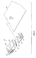
- FIG. 1 there is shown an exploded perspective view of a card reading system 20 incorporating features of the present invention.
- the present invention will be described with reference to the single embodiment shown in the drawings, it should be understood that the present invention can be embodied in many alternate forms of embodiments.
- any suitable size, shape or type of elements or materials could be used.
- the card reading system 20 is capable of accepting different sized disconnectible electronic cards, such as memory storage cards 22, 24, respectively.
- the memory storage card 22 is illustrated as a SIM-card while the memory storage card 24 is illustrated as a smart card as they have been earlier described.
- SIM-card SIM-card
- smart card smart card
- the system 20 includes a reader housing assembly 26 which is adapted to be electrically joined to an electrical connector, such as a style A-type USB plug connector 28.
- the reader housing assembly 26 includes a bottom tray member 30 which has a receiving surface 32 for one of the disconnectible memory storage card 22, 24.
- the receiving surface 32 extends between an entry slot 34 through which the memory storage cards 22, 24 are inserted into a connection chamber 36 and a stop surface 38 on a shoulder member 40 upstanding from the bottom tray member at a location distant from the entry slot.
- Laterally spaced apart tab members 42, 44 integral with the shoulder member 40 serve as locating indicia and project, respectively, toward the entry slot 34.
- the reader housing assembly 26 also includes a printed circuit board 46 overlying the card receiving surface 32 and, together with the card receiving surface of the bottom tray, defines the connection chamber 36.
- a connector 48 is mounted, for example, to traces (not shown) on the printed circuit board and includes a plurality of resilient contacts 50 projecting from a housing and toward the card receiving surface 32 and, therefore, transversely of a course to be taken by a disconnectible memory storage card as it is inserted into the housing assembly.
- a fixed cover 52 protectively overlies, and is in contiguous relationship with, the printed circuit board 46 and sandwiches the printed circuit board between the fixed cover and the bottom tray member 30. Similarly, contacts in connector 28 can secure to traces on PCB 46.
- the card receiving surface 32 of the bottom tray member 30 includes a prominence 54 for urging contact pads 56, 58 of the disconnectible memory storage cards 22, 24, respectively, into engagement with the resilient contacts 50 of the connector 48 in the connection chamber 36 of the reader housing assembly 26 when a disconnectible memory storage card is in a seated position.
- a prominence 54 could be the distal end of a cantilevered arm (not shown) in bottom tray 30 to provide a resilient feature.
- a movable cover 60 is pivotally mounted on and overlies the bottom tray member 30 and is movable between a first position indicated by solid lines in Fig. 3 for reception of either disconnectible memory storage card 22, 24 and a second position indicated by phantom lines in Fig. 3 upon reception of the second larger disconnectible memory storage card 24.
- the movable cover is biased toward the first position in a manner to be described.
- the movable cover 60 includes a top member 62 and a pair of parallel, spaced apart, side skirt members 64 depending from the top member.
- the card receiving surface 32 is straddled by the side skirt members 64.
- the side skirt members 64 are spaced to slidably receive therebetween the smaller disconnectible memory storage card 22.
- each of the side skirt members 64 extends to a cam edge 66 contoured to engageably receive the second larger disconnectible memory storage card 24.
- the movable cover is moved to the second phantom position of Fig. 3 when the second larger disconnectible memory storage card 24 achieves the seated position.
- the fixed cover 52 includes a pair of downwardly extending flange members 68 parallel to and proximately spaced from the side skirt members 64 of the movable cover 60.
- Spaced apart pivot joints 70 between each of the side skirt members 64 of the movable cover 60 and the flange members 68 enable movement of the movable cover between the first and second positions earlier described.
- Each pivot joint is composed of a stub shaft 72 fixed to and projecting laterally away from its associated flange member and a mating bore 74 in each side skirt member 64 which freely receives an associated stub shaft.
- Other hinge assemblies could also be used.
- the movable cover 60 further includes a front skirt member 74 integrally joining and extending between the side skirt members 64 and extending to a free bottom edge 76 which is sufficiently spaced from the card receiving surface 32 of the bottom tray member 30 when the movable cover is in the first or lowered or solid line position of Fig. 3 to permit insertion of a disconnectible memory storage card 22, 24 through the entry slot 34.
- Skirt 74 does, however, sufficiently protect entry slot 34 (and the inner components of system 20) from dust and debris.
- An elliptic spring 78 is integral with and projects from each of the side skirt members 64 engaged with an associated one of a pair of ledges 80 on the shoulder members 42, 44. The springs 78 thereby operate mutually to bias the movable cover 60 toward the first position as earlier defined.
- the card reading system 20 accommodates both a first smaller rectangular disconnectible memory storage card 22 and a second larger rectangular disconnectible memory storage card 24.
- a first minor edge 82 is in contiguous engagement with the stop surface 38 and with major edges 84, 86 adjacent the first minor edge being contiguous, respectively, with the locating indicia in the form of the tab members 42, 44.
- the width of the card 42 that is, the distance between the edges 84, 86 is less than the distance between the side skirt members 64 at the entry slot 34.
- the movable cover 60 remains in the solid line position (Fig. 3) when the card 22 is introduced into the reader housing assembly 26.
- the contact pads 56 are mechanically and electrically engaged with the resilient contacts 50 on the connector 48.
- the reader housing assembly 26 also accommodates the larger rectangular disconnectible memory storage card 24 which is defined by opposed minor edges 88 and opposed major edges 90.
- a pair of spaced apart locating indicia 92 are provided in a foremost minor edge 88.
- the locating indicia 92 are sized and positioned for mating engagement with the spaced apart locating indicia in the form of the tab members 42, 44 of the reader housing assembly 26 when inserted into the connection chamber 36 through the entry slot 34 and advanced to a seated position at which the foremost minor edge 88 is in contiguous engagement with the stop surface 38.
- the foremost minor edge 88 engages the cam edges of the side skirt members, raising the front skirt member 74 and pivoting the entire movable cover 60 against the bias of the elliptic springs 78.
- the contact pads 58 are mechanically and electrically engaged with the resilient contacts 50 on the connector 48.
- the invention may also employ a further expedient as a failsafe measure to assure that the cards 22, 24 will be properly positioned, and not upside down, when introduced through the entry slot 34.
- the reader housing assembly 26 may include mutually cooperating indicia on the reader housing assembly and on each of the disconnectible memory storage cards permitting only one orientation of a disconnectible memory storage card when advanced to the seated position in the connection chamber. More specifically, a corner projection 93 is provided at the intersection between the stop surface 38 and the tab member 44 intended to contiguously interface with similarly fashioned beveled edges 94, 96 on the cards 22, 24, respectively, when the cards are fully seated in the reader housing assembly 26.
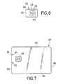
- a modified reader housing assembly 98 is similar to the reader housing assembly 26 previously described but lacks the movable cover 60.
- the modified reader housing assembly 98 includes a bottom tray member 30A having a disconnectible memory storage card receiving surface 32A extending between the entry slot 34 and the stop surface 38 on a shoulder member 40.
- a resilient finger member 100 has a domed prominence 102 at a cantilevered free end of the finger member and projects toward the connector 48 in the connector chamber 36. The finger member 100 is biased toward a normally closed position indicated by solid lines in Fig.
- the electronic card 24A is formed with a locking aperture 104 located between the first minor edge 88 and the contact pads 58. It will be appreciated that the electronic, or memory storage, card 22 may be similarly modified.
- the finger member is again movable to the closed position when the disconnectible electronic card reaches the seated position. In this position of the electronic card 98, the prominence 102 is received in the locking aperture 104 of the electronic card.
- the electronic card 24A and the reader housing assembly 98 are thereby locked together, but with moderate force applied to the electronic card by the user, it can easily be withdrawn from the reader housing assembly.
Landscapes
- Engineering & Computer Science (AREA)
- Artificial Intelligence (AREA)
- Computer Vision & Pattern Recognition (AREA)
- Physics & Mathematics (AREA)
- General Physics & Mathematics (AREA)
- Theoretical Computer Science (AREA)
- Coupling Device And Connection With Printed Circuit (AREA)
- Details Of Connecting Devices For Male And Female Coupling (AREA)
- Credit Cards Or The Like (AREA)
Applications Claiming Priority (2)
| Application Number | Priority Date | Filing Date | Title |
|---|---|---|---|
| US605756 | 1990-10-30 | ||
| US09/605,756 US6234844B1 (en) | 2000-06-28 | 2000-06-28 | Electronic card connector |
Publications (2)
| Publication Number | Publication Date |
|---|---|
| EP1168228A2 true EP1168228A2 (de) | 2002-01-02 |
| EP1168228A3 EP1168228A3 (de) | 2002-08-21 |
Family
ID=24425085
Family Applications (1)
| Application Number | Title | Priority Date | Filing Date |
|---|---|---|---|
| EP01114843A Withdrawn EP1168228A3 (de) | 2000-06-28 | 2001-06-28 | Verbinder für elektronische Karte |
Country Status (3)
| Country | Link |
|---|---|
| US (1) | US6234844B1 (de) |
| EP (1) | EP1168228A3 (de) |
| JP (1) | JP2002063956A (de) |
Families Citing this family (33)
| Publication number | Priority date | Publication date | Assignee | Title |
|---|---|---|---|---|
| US6230006B1 (en) | 1997-09-08 | 2001-05-08 | Acterna, Llc | Test system for remotely testing switches within a telecommunications network |
| US7020441B2 (en) * | 1998-09-03 | 2006-03-28 | Casabyte, Inc. | Test system for remotely testing switches within a telecommunications network |
| FI991002L (fi) * | 1999-05-03 | 2000-11-04 | Nokia Mobile Phones Ltd | Toimikorttiliitin ja matkaviestin |
| US6859369B2 (en) * | 2000-07-06 | 2005-02-22 | Onspec Electronic Inc. | Smartuniversal flash media card adapters |
| US7493437B1 (en) * | 2000-07-06 | 2009-02-17 | Mcm Portfolio Llc | Flashtoaster for reading several types of flash memory cards with or without a PC |
| US7295443B2 (en) | 2000-07-06 | 2007-11-13 | Onspec Electronic, Inc. | Smartconnect universal flash media card adapters |
| US7278051B2 (en) | 2000-07-06 | 2007-10-02 | Onspec Electronic, Inc. | Field-operable, stand-alone apparatus for media recovery and regeneration |
| US7252240B1 (en) | 2000-07-06 | 2007-08-07 | Onspec Electronics, Inc. | Memory module which includes a form factor connector |
| US6438638B1 (en) * | 2000-07-06 | 2002-08-20 | Onspec Electronic, Inc. | Flashtoaster for reading several types of flash-memory cards with or without a PC |
| US6435409B1 (en) * | 2001-03-23 | 2002-08-20 | Kuang-Hua Hu | Card reader structure with an axial-rotate joint |
| TW520094U (en) * | 2001-12-19 | 2003-02-01 | I O Interconnect Inc | Memory card connecting seat assembly and its detection device |
| CN2517012Y (zh) * | 2002-01-23 | 2002-10-16 | 台均实业有限公司 | 可随意升级扩容更换存储介质的usb移动存储器 |
| US6985756B2 (en) * | 2002-05-09 | 2006-01-10 | Casabyte, Inc. | Method, apparatus and article to remotely associate wireless communications devices with subscriber identities and/or proxy wireless communications devices |
| AU2003240938A1 (en) * | 2002-05-31 | 2003-12-19 | Simpletech, Inc. | Removable storage device |
| JP4039518B2 (ja) * | 2002-09-09 | 2008-01-30 | タイコエレクトロニクスアンプ株式会社 | カード用コネクタ |
| JP2005085707A (ja) | 2003-09-10 | 2005-03-31 | Jst Mfg Co Ltd | メモリカード用コネクタ及びコネクタユニット |
| DE202004000179U1 (de) * | 2004-01-09 | 2004-03-18 | Stocko Contact Gmbh & Co. Kg | Kontaktiereinheit für ein kartenförmiges Trägerelement elektronischer Baugruppen |
| DE102004054150B4 (de) * | 2004-11-08 | 2007-11-29 | Lumberg Connect Gmbh | Kontaktiervorrichtung für eine Chipkarte, insbesondere für eine SIM- oder USIM-Karte |
| EP1864236A1 (de) * | 2005-02-17 | 2007-12-12 | Acterna, LLC | Verfahren und vorrichtungen zum entfernten testen von kommunikationsneztwerken unter der benutzung von digitalen fingerabdrücken von inhalten |
| US20070045417A1 (en) * | 2005-08-26 | 2007-03-01 | Ming-Chih Tsai | USB device having IC card reader/writer and flash memory disk functions |
| US8070067B2 (en) * | 2005-12-22 | 2011-12-06 | Industrial Technology Research Institute | Receptacles for removable electrical interface devices |
| US20070281524A1 (en) * | 2006-05-31 | 2007-12-06 | Sandisk Il Ltd. | Detachable USB card connector |
| US7798840B2 (en) * | 2007-01-05 | 2010-09-21 | Sandisk Corporation | Expandable and collapsible peripheral device |
| US7686654B2 (en) * | 2007-06-29 | 2010-03-30 | Sandisk Corporation | Memory card for an ExpressCard slot |
| US7699660B2 (en) * | 2007-06-29 | 2010-04-20 | Sandisk Corporation | Adapter for an expresscard slot |
| US8561295B2 (en) * | 2007-06-29 | 2013-10-22 | Sandisk Technologies Inc. | Method of adapting an expresscard slot for smaller form factor memory compatibility |
| US7780477B2 (en) * | 2007-06-29 | 2010-08-24 | Sandisk Corporation | Adapter system for use with an expresscard slot |
| US7779184B2 (en) * | 2007-06-29 | 2010-08-17 | Sandisk Corporation | Method of using the dual bus interface in an expresscard slot |
| US8051229B2 (en) * | 2007-06-29 | 2011-11-01 | Sandisk Technologies Inc. | Dual bus ExpressCard peripheral device |
| CN102647490A (zh) * | 2012-03-31 | 2012-08-22 | 惠州Tcl移动通信有限公司 | 一种超薄无线通信装置 |
| GB2501321A (en) | 2012-04-20 | 2013-10-23 | Powa Technologies Ltd | Smart-card reader device with means for ensuring card alignment |
| TWM482876U (zh) * | 2014-01-17 | 2014-07-21 | Wistron Corp | 電子卡連接器及裝有電子卡連接器的電子裝置 |
| CN108462765A (zh) * | 2018-01-26 | 2018-08-28 | 努比亚技术有限公司 | 终端 |
Family Cites Families (18)
| Publication number | Priority date | Publication date | Assignee | Title |
|---|---|---|---|---|
| DE3503575A1 (de) * | 1985-02-02 | 1986-08-07 | Robert Bosch Gmbh, 7000 Stuttgart | Elektrisches durchschaltgeraet |
| US4931622A (en) | 1985-08-09 | 1990-06-05 | Daiichi Denshi Kogyo Kabushiki Kaisha | Electronic card receiving device and ejection mechanism |
| JPS63124183A (ja) * | 1986-11-14 | 1988-05-27 | Nec Corp | Icカ−ドインタ−フエ−ス機構 |
| US5281148A (en) | 1992-09-15 | 1994-01-25 | Trakker, Inc. | Electrical circuit card connector |
| FR2728709B1 (fr) | 1994-07-13 | 1997-01-24 | Schlumberger Ind Sa | Interface portable pour carte a puce electronique |
| US5660568A (en) | 1995-01-04 | 1997-08-26 | Simple Technology, Inc. | Communications card with integral transmission media line adaptor |
| DE19515713A1 (de) * | 1995-04-28 | 1996-10-31 | Amphenol Tuchel Elect | Lesevorrichtung für Chipkarten und SIM-Karten |
| DE19527519C2 (de) | 1995-07-27 | 2000-11-09 | Amphenol Tuchel Elect | Chipkartenleser mit absenkbarer Kartenführung |
| DE29518707U1 (de) * | 1995-11-25 | 1996-01-18 | Stocko Metallwarenfabriken Henkels Und Sohn Gmbh & Co, 42327 Wuppertal | Kontaktiereinheit für kartenförmige Trägerelemente elektronischer Baugruppen |
| JP2721329B2 (ja) | 1995-12-28 | 1998-03-04 | 山一電機株式会社 | カードイン形コネクタ |
| US5752857A (en) | 1996-05-24 | 1998-05-19 | Itt Corporation | Smart card computer adaptor |
| US5854891A (en) | 1996-08-09 | 1998-12-29 | Tritheim Technologies, Inc. | Smart card reader having multiple data enabling storage compartments |
| US5780827A (en) | 1996-10-16 | 1998-07-14 | Verifone, Inc. | Landing contact mechanism and card latch for smart card reader/writer |
| JP3585336B2 (ja) * | 1997-02-24 | 2004-11-04 | 沖電気工業株式会社 | Icカードアダプタ |
| GB2322723B (en) | 1997-02-26 | 2000-12-20 | Whitaker Corp | Card reader having a configurable switch |
| DE29704984U1 (de) | 1997-03-19 | 1997-05-07 | Stocko Metallwarenfabriken Henkels & Sohn GmbH & Co, 42327 Wuppertal | Adapter für die Kontaktierung von kartenförmigen Trägerelementen |
| DE19729397A1 (de) * | 1997-07-09 | 1998-11-05 | Siemens Ag | Anordnung zur Aufnahme kartenförmiger Datenträger |
| EP0950975A3 (de) * | 1998-02-20 | 2000-02-02 | The Whitaker Corporation | Kartenleser |
-
2000
- 2000-06-28 US US09/605,756 patent/US6234844B1/en not_active Expired - Lifetime
-
2001
- 2001-06-28 EP EP01114843A patent/EP1168228A3/de not_active Withdrawn
- 2001-06-28 JP JP2001196675A patent/JP2002063956A/ja active Pending
Also Published As
| Publication number | Publication date |
|---|---|
| EP1168228A3 (de) | 2002-08-21 |
| JP2002063956A (ja) | 2002-02-28 |
| US6234844B1 (en) | 2001-05-22 |
Similar Documents
| Publication | Publication Date | Title |
|---|---|---|
| US6234844B1 (en) | Electronic card connector | |
| US6095868A (en) | Card reader connector having a separable cover | |
| US5877488A (en) | Combination chip card reader | |
| KR100675206B1 (ko) | 카드 접속용 어댑터 | |
| JP3173438B2 (ja) | メモリカード及び装着装置 | |
| EP1152492B1 (de) | Kartenverbinder | |
| US6402529B2 (en) | Card connector | |
| US7427206B2 (en) | Card connector | |
| CA1223655A (en) | Device for reading and writing ic-external storage card | |
| EP1052590B1 (de) | Zwischensockel für Karte | |
| US5993261A (en) | Adaptor for contacting card-shaped supports | |
| US6496381B1 (en) | Contact arrangement and counter-contact module | |
| JPS6277996A (ja) | Icカ−ド | |
| EP1324256B1 (de) | Kartenverbinder | |
| EP1406204B1 (de) | Kartenhalter für ein Handy | |
| US6672514B1 (en) | Portable smart card reader assembly | |
| US7350705B1 (en) | Compact robust smart card reader | |
| US7659606B2 (en) | Contacting unit | |
| KR102141911B1 (ko) | Ic 카드 단말기 | |
| JP4530318B2 (ja) | プラグイン型icカード用アダプタ | |
| US6869017B2 (en) | Card connector | |
| US7372136B2 (en) | Chip card retaining mechanism | |
| JP2002373740A (ja) | カード用コネクタ装置 | |
| JP3827578B2 (ja) | カード用コネクタ装置 | |
| US6070797A (en) | Positioning device for a smart card reader |
Legal Events
| Date | Code | Title | Description |
|---|---|---|---|
| PUAI | Public reference made under article 153(3) epc to a published international application that has entered the european phase |
Free format text: ORIGINAL CODE: 0009012 |
|
| AK | Designated contracting states |
Kind code of ref document: A2 Designated state(s): AT BE CH CY DE DK ES FI FR GB GR IE IT LI LU MC NL PT SE TR |
|
| AX | Request for extension of the european patent |
Free format text: AL;LT;LV;MK;RO;SI |
|
| PUAL | Search report despatched |
Free format text: ORIGINAL CODE: 0009013 |
|
| AK | Designated contracting states |
Kind code of ref document: A3 Designated state(s): AT BE CH CY DE DK ES FI FR GB GR IE IT LI LU MC NL PT SE TR |
|
| AX | Request for extension of the european patent |
Free format text: AL;LT;LV;MK;RO;SI |
|
| RIC1 | Information provided on ipc code assigned before grant |
Free format text: 7G 06K 7/00 A, 7G 06K 7/015 B |
|
| 17P | Request for examination filed |
Effective date: 20030207 |
|
| AKX | Designation fees paid |
Designated state(s): AT BE CH CY DE DK ES FI FR GB GR IE IT LI LU MC NL PT SE TR |
|
| 17Q | First examination report despatched |
Effective date: 20070706 |
|
| STAA | Information on the status of an ep patent application or granted ep patent |
Free format text: STATUS: THE APPLICATION IS DEEMED TO BE WITHDRAWN |
|
| 18D | Application deemed to be withdrawn |
Effective date: 20091119 |