EP1168416A1 - Lampe électrique à configuration de pincement pour la protection du queusot - Google Patents
Lampe électrique à configuration de pincement pour la protection du queusot Download PDFInfo
- Publication number
- EP1168416A1 EP1168416A1 EP01114446A EP01114446A EP1168416A1 EP 1168416 A1 EP1168416 A1 EP 1168416A1 EP 01114446 A EP01114446 A EP 01114446A EP 01114446 A EP01114446 A EP 01114446A EP 1168416 A1 EP1168416 A1 EP 1168416A1
- Authority
- EP
- European Patent Office
- Prior art keywords
- lamp
- press seal
- exhaust tube
- recess
- seal
- Prior art date
- Legal status (The legal status is an assumption and is not a legal conclusion. Google has not performed a legal analysis and makes no representation as to the accuracy of the status listed.)
- Withdrawn
Links
- 238000000034 method Methods 0.000 claims description 9
- 238000010438 heat treatment Methods 0.000 claims description 4
- 238000003780 insertion Methods 0.000 description 7
- 230000037431 insertion Effects 0.000 description 7
- 230000015572 biosynthetic process Effects 0.000 description 2
- 238000007789 sealing Methods 0.000 description 2
- 238000004891 communication Methods 0.000 description 1
- 239000011521 glass Substances 0.000 description 1
- 238000012986 modification Methods 0.000 description 1
- 230000004048 modification Effects 0.000 description 1
- 238000004904 shortening Methods 0.000 description 1
Images

Classifications
-
- H—ELECTRICITY
- H01—ELECTRIC ELEMENTS
- H01J—ELECTRIC DISCHARGE TUBES OR DISCHARGE LAMPS
- H01J5/00—Details relating to vessels or to leading-in conductors common to two or more basic types of discharge tubes or lamps
- H01J5/50—Means forming part of the tube or lamps for the purpose of providing electrical connection to it
- H01J5/52—Means forming part of the tube or lamps for the purpose of providing electrical connection to it directly applied to or forming part of the vessel
-
- H—ELECTRICITY
- H01—ELECTRIC ELEMENTS
- H01J—ELECTRIC DISCHARGE TUBES OR DISCHARGE LAMPS
- H01J5/00—Details relating to vessels or to leading-in conductors common to two or more basic types of discharge tubes or lamps
- H01J5/32—Seals for leading-in conductors
- H01J5/38—Pinched-stem or analogous seals
-
- H—ELECTRICITY
- H01—ELECTRIC ELEMENTS
- H01J—ELECTRIC DISCHARGE TUBES OR DISCHARGE LAMPS
- H01J61/00—Gas-discharge or vapour-discharge lamps
- H01J61/02—Details
- H01J61/30—Vessels; Containers
-
- H—ELECTRICITY
- H01—ELECTRIC ELEMENTS
- H01J—ELECTRIC DISCHARGE TUBES OR DISCHARGE LAMPS
- H01J61/00—Gas-discharge or vapour-discharge lamps
- H01J61/02—Details
- H01J61/36—Seals between parts of vessels; Seals for leading-in conductors; Leading-in conductors
- H01J61/366—Seals for leading-in conductors
- H01J61/368—Pinched seals or analogous seals
-
- H—ELECTRICITY
- H01—ELECTRIC ELEMENTS
- H01J—ELECTRIC DISCHARGE TUBES OR DISCHARGE LAMPS
- H01J9/00—Apparatus or processes specially adapted for the manufacture, installation, removal, maintenance of electric discharge tubes, discharge lamps, or parts thereof; Recovery of material from discharge tubes or lamps
- H01J9/24—Manufacture or joining of vessels, leading-in conductors or bases
- H01J9/32—Sealing leading-in conductors
- H01J9/323—Sealing leading-in conductors into a discharge lamp or a gas-filled discharge device
- H01J9/326—Sealing leading-in conductors into a discharge lamp or a gas-filled discharge device making pinched-stem or analogous seals
-
- H—ELECTRICITY
- H01—ELECTRIC ELEMENTS
- H01K—ELECTRIC INCANDESCENT LAMPS
- H01K1/00—Details
- H01K1/38—Seals for leading-in conductors
Definitions
- This invention relates to electric lamps and, more particularly, to electric lamps wherein the lamp envelope is sealed with a press seal, and an exhaust tube extends through the press seal.
- incandescent electric lamp is a so-called S-8 wedge type lamp used for automobile brake light, turn signal and tail light applications.
- Such lamps typically include one or more filaments located within a lamp envelope. Electrical leads extend through a press seal for connection to an energy source.
- an exhaust tube extends through the press seal to the enclosed volume of the lamp envelope. The exhaust tube is used to fill the enclosed volume of the lamp envelope with a desired gas fill after formation of the press seal. The exhaust tube is then tipped off, or sealed, by heating the glass tube.
- the lamp is mounted in a plastic base that attaches to the press seal. A lamp assembly, including the lamp and the base, is inserted into a socket in the automobile or other vehicle.
- Wedge-type incandescent electric lamps which utilize an insulating base are disclosed, for example, in U.S. Patent No. 4,603,278, issued July 29, 1986 to Devir et al.; U.S. Patent No. 4,752,710, issued June 21, 1988 to Devir et al.; U.S. Patent No. 4,877,992, issued October 31, 1989 to Devir; U.S. Patent No. 4,979,082, issued December 18, 1990 to Devir; U.S. Patent No. 5,008,588, issued April 16, 1991 to Nakahara; U.S. Patent No. 5,061,873, issued October 29, 1991 to Belliveau; U.S. Patent No. 5,186,669, issued February 16, 1993 to Holman et al; U.S. Patent No. 5,278,741, issued January 11, 1994 to Ehrman; and U.S. Patent No. 6,056,417 issued May 2, 2000 to Cheng. None of the prior art known to Applicants has addressed the breakage problem described above.
- an electric lamp comprising a light-transmissive lamp envelope defining an enclosed volume, the lamp envelope having a seal and the seal having a recess, a light source disposed in the enclosed volume of the lamp envelope, electrical leads extending through the seal and connected to the light source, and an exhaust tube extending through the recess in the seal to the enclosed volume of the lamp envelope.
- the seal preferably comprises a press seal.
- the exhaust tube includes an exposed portion external to the press seal. A substantial part of the exposed portion of the exhaust tube is positioned within the recess, so that the exhaust tube is at least partially shielded against breakage.
- the exposed portion of the exhaust tube external to the press seal may have a length that is less than the length of the press seal.
- the exhaust tube may have an outside diameter that is less than the thickness of the press seal for further shielding of the exhaust tube.
- a lamp assembly comprises an electric lamp and a lamp base.
- the electric lamp may be configured as described above.
- the lamp base is secured to the press seal.
- a method for making an electric lamp.
- the method comprises the steps of providing a light-transmissive lamp envelope having an interior volume and an opening communicating with the interior volume, positioning a filament assembly and an exhaust tube in the opening, heating the lamp envelope at least in the region of the opening, forming the lamp envelope into a press seal such that electrical leads of the filament assembly and the exhaust tube extend through the press seal into the interior volume of the lamp envelope, and pushing the exhaust tube toward the interior volume of the lamp envelope with the lamp envelope heated to form a recess in the press seal where the exhaust tube extends into the lamp envelope.
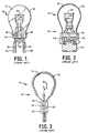
- a prior art wedge-type lamp is shown in Fig. 1.
- a lamp assembly incorporating the lamp of Fig. 1 is shown in Figs. 2 and 3.
- a lamp 10 includes a lamp envelope 12 that defines an enclosed volume 14. Lamp envelope 12 is closed at one end by a press seal 16 having locating grooves 18.
- An exhaust tube 20 extends through press seal 16 to enclosed volume 14. In the completed lamp, exhaust tube 20 is sealed at its outer end. Filaments 24 and 26 are mounted within lamp envelope 12. Electrical leads 30 and 32 extend through press seal 16 and are connected to filament 24. Electrical leads 34 and 36 extend through press seal 16 and are connected to filament 26.
- a lamp assembly 40 including lamp 10 and an insulating base 42 is shown in Figs. 2 and 3.
- Insulating base 42 is typically a plastic element that has a cavity 44 for receiving press seal 16, exhaust tube 20 and electrical leads 30, 32, 34 and 36 of lamp 10.
- Base 42 is secured to press seal 16 to form lamp assembly 40.
- Base 42 may include projections 46 that engage locating grooves 18 in press seal 16, so as to locate base 42 relative to lamp envelope 12.
- lamp assembly 40 is inserted into a lamp socket in an automobile or other vehicle.
- the insertion process may be manual or automatic. In either case, lateral forces may be applied to the lamp assembly, causing lamp 10 to pivot relative to base 42. This may cause exhaust tube 20 to contact the inside wall of cavity 44 in base 42, often resulting in breakage of exhaust tube 20 and failure of lamp 10.
- a lamp 110 in accordance with an embodiment of the invention is shown in Figs. 4 and 5.
- a lamp assembly incorporating lamp 110 is shown in Figs. 6 and 7.
- Lamp 110 includes a lamp envelope 112 which defines an enclosed volume 114.
- One end of lamp envelope 112 is closed by a press seal 116.
- Press seal 116 may be provided with lateral grooves 118 for locating lamp 110 relative to a base.
- An exhaust tube 120 extends through press seal 116 to enclosed volume 114. In the completed lamp, exhaust tube 120 is sealed at its outer end.
- Filaments 124 and 126 are positioned within the enclosed volume 114 of lamp envelope 112. Electrical leads 130 and 132 extend through press seal 116 and are connected to filament 124. Electrical leads 134 and 136 extend through press seal 116 and are connected to filament 126. Electrical leads 130, 132, 134 and 136 conduct electrical current to filaments 124 and 126 and provide mechanical support for filaments 124 and 126 within lamp envelope 112. It will be understood that a single filament or more than two filaments may be utilized within the scope of the invention.
- a lamp assembly 140 incorporating lamp 110 and an insulating base 142 is shown in Figs. 6 and 7.
- Insulating base 142 is provided with a cavity 144 for receiving press seal 116, exhaust tube 120 and electrical leads 130, 132, 134 and 136 of lamp 110.
- Insulating base 142 typically fabricated of plastic, is secured to press seal 116 to form lamp assembly 140.
- Base 142 may be provided with projections 146 which engage grooves 118 in press seal 116 and which locate base 142 relative to lamp 110.
- exhaust tube 120 when the exhaust tube is heated for tip off following introduction of the desired fill gas into enclosed volume 114, thermal transients may cause breakage of exhaust tube 120 at the region where it emerges from press seal 116. For this reason, the minimum length of exposed portion of exhaust tube 120 is limited. In one example, the exposed portion of exhaust tube 120 has a length 160 of 0.180 inch, and recess 152 has a depth 162 of 0.080 inch in a lamp assembly having an overall length of 2.06 inches. Thus, exhaust tube 120 is at least partially shielded against breakage within recess 152 in press seal 116.
- exhaust tube 120 and recess 152 are preferably located at the center of the lower edge 150 of press seal 116 and are located between electrical leads 130 and 134 on one side and electrical leads 132 and 136 on the opposite side.
- exhaust tube 120 and recess 152 may have any desired location on press seal 116.
- a length 164 of press seal 116 is increased in comparison with prior art lamps.
- press seal 116 has a length 164 of 0.245 inch.
- the length 164 of press seal 116 is greater than the length 160 of the exposed portion of exhaust tube 120.
- the outside diameter of exhaust tube 120 is preferably less than a thickness 166 of press seal 116 in order to shield the exposed portion of exhaust tube 120 from external mechanical forces.
- exhaust tube 120 has an outside diameter of 0.100 inch
- press seal 116 has a thickness 166 of no less than 0.107 inch. The thickness 166 of press seal 116 is selected to deter movement of lamp 110 relative to base 142.
- Lamp 110 may be fabricated, for example, by the following process.
- a lamp envelope having an opening communicating with an interior volume is provided.
- a filament assembly including filaments 124 and 126 attached to the respective electrical leads 130, 132, 134 and 136, is positioned in the opening, with filaments 124 and 126 located within the lamp envelope and electrical leads 130, 132, 134 and 136 extending to the exterior of the lamp envelope.
- exhaust tube 120 is positioned in the opening, of the lamp envelope to permit communication with the interior volume of the lamp envelope after formation of the press seal. Then, the lamp envelope is heated in the region of the opening, and a press seal is formed using known press sealing techniques.
- exhaust tube 120 While the press seal is heated to a plastic state, exhaust tube 120 is pushed inwardly along its axis toward filaments 124 and 126, thereby deforming the press seal and producing recess 152 in the lower edge 150 of press seal 116. The press seal is allowed to cool. Then, the desired gas fill is introduced into enclosed volume 114 through exhaust tube 120. Exhaust tube 120 is tipped off by heating it at the desired tip off location to cause sealing and to permit removal of the excess length of exhaust tube 120.
- Lamps of the type shown in Figs. 4-7 and described above are commonly known as S-8 wedge-type lamps and are used for brake light, turn signal and tail light applications in automobiles and other vehicles.
- the present invention is not limited to these lamps.
Landscapes
- Engineering & Computer Science (AREA)
- Manufacturing & Machinery (AREA)
- Vessels And Coating Films For Discharge Lamps (AREA)
Applications Claiming Priority (2)
| Application Number | Priority Date | Filing Date | Title |
|---|---|---|---|
| US596777 | 1984-04-04 | ||
| US09/596,777 US6486595B1 (en) | 2000-06-19 | 2000-06-19 | Electric lamp having press seal configuration for exhaust tube protection |
Publications (1)
| Publication Number | Publication Date |
|---|---|
| EP1168416A1 true EP1168416A1 (fr) | 2002-01-02 |
Family
ID=24388649
Family Applications (1)
| Application Number | Title | Priority Date | Filing Date |
|---|---|---|---|
| EP01114446A Withdrawn EP1168416A1 (fr) | 2000-06-19 | 2001-06-15 | Lampe électrique à configuration de pincement pour la protection du queusot |
Country Status (4)
| Country | Link |
|---|---|
| US (1) | US6486595B1 (fr) |
| EP (1) | EP1168416A1 (fr) |
| CA (1) | CA2344562A1 (fr) |
| MX (1) | MXPA01005626A (fr) |
Cited By (1)
| Publication number | Priority date | Publication date | Assignee | Title |
|---|---|---|---|---|
| EP1755146A3 (fr) * | 2005-06-20 | 2008-05-07 | Osram-Sylvania Inc. | Chambre à décharge en céramique à capillaires reliés |
Citations (8)
| Publication number | Priority date | Publication date | Assignee | Title |
|---|---|---|---|---|
| US3551725A (en) * | 1969-03-07 | 1970-12-29 | Westinghouse Electric Corp | Method of tipping-off the exhaust tube of an electric lamp,and a baseless single-ended incandescent lamp produced by such method |
| US3857056A (en) * | 1973-10-26 | 1974-12-24 | Gen Motors Corp | Wedge base light bulb |
| US4979082A (en) * | 1989-06-02 | 1990-12-18 | Gte Products Corporation | Relieved plastic lamp base |
| EP0415483A1 (fr) * | 1989-08-28 | 1991-03-06 | Koninklijke Philips Electronics N.V. | Lampe électrique |
| US5008588A (en) * | 1988-06-22 | 1991-04-16 | Ichikoh Industries, Ltd. | Wedge-type lamp bulb assembly |
| US5186669A (en) * | 1990-02-01 | 1993-02-16 | Cooper Industries, Inc. | Incandescent lamp |
| EP0924745A2 (fr) * | 1997-12-16 | 1999-06-23 | Hitachi, Ltd. | Lampe fluorescente et son procédé de fabrication |
| US6056417A (en) * | 1998-11-16 | 2000-05-02 | Eiko, Ltd | Two-part wedge base for lamp |
Family Cites Families (8)
| Publication number | Priority date | Publication date | Assignee | Title |
|---|---|---|---|---|
| DE3112821A1 (de) * | 1981-03-31 | 1982-10-14 | Patent-Treuhand-Gesellschaft für elektrische Glühlampen mbH, 8000 München | Elektrische lampe mit einer als quetschung ausgebildeten gefaesseinschmelzung sowie vorrichtung und verfahren zur herstellung |
| US4603278A (en) | 1984-02-16 | 1986-07-29 | Gte Products Corporation | Electric lamp with insulating base |
| US4752710A (en) | 1986-01-06 | 1988-06-21 | Gte Products Corporation | Electric lamp with insulating base providing improved wire retention |
| US4877992A (en) | 1987-07-09 | 1989-10-31 | Gte Products Corporation | Electric lamp having conductors with means formed therein for removing contact surface material |
| US5061873A (en) | 1990-02-02 | 1991-10-29 | General Electric Company | Incandecent lamp having high resistance to filament damage from vibration and shock |
| US5105119A (en) * | 1990-09-21 | 1992-04-14 | North American Philips Corporation | Electric lamp having a pressure molded base |
| IL99826A (en) | 1991-10-23 | 1996-10-16 | Raviv Moulds And Injection Mou | Light bulb assembly particularly useful for miniature lamps |
| US6232707B1 (en) * | 1998-11-16 | 2001-05-15 | General Electric Company | Wedge base lamp |
-
2000
- 2000-06-19 US US09/596,777 patent/US6486595B1/en not_active Expired - Fee Related
-
2001
- 2001-05-03 CA CA002344562A patent/CA2344562A1/fr not_active Abandoned
- 2001-06-05 MX MXPA01005626A patent/MXPA01005626A/es active IP Right Grant
- 2001-06-15 EP EP01114446A patent/EP1168416A1/fr not_active Withdrawn
Patent Citations (8)
| Publication number | Priority date | Publication date | Assignee | Title |
|---|---|---|---|---|
| US3551725A (en) * | 1969-03-07 | 1970-12-29 | Westinghouse Electric Corp | Method of tipping-off the exhaust tube of an electric lamp,and a baseless single-ended incandescent lamp produced by such method |
| US3857056A (en) * | 1973-10-26 | 1974-12-24 | Gen Motors Corp | Wedge base light bulb |
| US5008588A (en) * | 1988-06-22 | 1991-04-16 | Ichikoh Industries, Ltd. | Wedge-type lamp bulb assembly |
| US4979082A (en) * | 1989-06-02 | 1990-12-18 | Gte Products Corporation | Relieved plastic lamp base |
| EP0415483A1 (fr) * | 1989-08-28 | 1991-03-06 | Koninklijke Philips Electronics N.V. | Lampe électrique |
| US5186669A (en) * | 1990-02-01 | 1993-02-16 | Cooper Industries, Inc. | Incandescent lamp |
| EP0924745A2 (fr) * | 1997-12-16 | 1999-06-23 | Hitachi, Ltd. | Lampe fluorescente et son procédé de fabrication |
| US6056417A (en) * | 1998-11-16 | 2000-05-02 | Eiko, Ltd | Two-part wedge base for lamp |
Cited By (1)
| Publication number | Priority date | Publication date | Assignee | Title |
|---|---|---|---|---|
| EP1755146A3 (fr) * | 2005-06-20 | 2008-05-07 | Osram-Sylvania Inc. | Chambre à décharge en céramique à capillaires reliés |
Also Published As
| Publication number | Publication date |
|---|---|
| CA2344562A1 (fr) | 2001-12-19 |
| US6486595B1 (en) | 2002-11-26 |
| MXPA01005626A (es) | 2003-08-20 |
Similar Documents
| Publication | Publication Date | Title |
|---|---|---|
| EP0151806B1 (fr) | Lampe électrique à culot isolant | |
| US5239226A (en) | Replaceable lamp assembly for automotive headlamps | |
| US3885149A (en) | Lamp pinch seals | |
| CA1253563A (fr) | Lampe electrique a cabochon | |
| US4752710A (en) | Electric lamp with insulating base providing improved wire retention | |
| US4028577A (en) | Electric lamp with insulating base | |
| HU202332B (en) | Vehicle reflector lamp and method for making said lamp | |
| US4139794A (en) | Wedge-pin glass halogen lamp with transverse reference feature | |
| US3979627A (en) | Electric lamp with insulating base | |
| HU221363B1 (en) | Electric lamp | |
| US4126810A (en) | Ceramic base for glass halogen lamps | |
| KR100278396B1 (ko) | 방전 램프 장치 및 그것의 절연 플러그 | |
| WO1998000854A1 (fr) | Ampoule electrique | |
| EP0909458B1 (fr) | Ampoule electrique a culot | |
| US6486595B1 (en) | Electric lamp having press seal configuration for exhaust tube protection | |
| US5659222A (en) | Vacuum sealed incandescent lamp with improved filament support structure | |
| US4877992A (en) | Electric lamp having conductors with means formed therein for removing contact surface material | |
| US4180758A (en) | Capless electric incandescent lamp | |
| EP0464722B1 (fr) | Lampe fluorescente à ouverture et à embases à pincement | |
| US3904909A (en) | Pinch-sealed electric lamps | |
| CA2317883A1 (fr) | Lampe munie d'une base fixee avec une pince formee et cimentee | |
| US4988912A (en) | Electric lamp and method of manufacturing same | |
| KR100712745B1 (ko) | 전기 램프 | |
| US6525454B2 (en) | Electric lamp | |
| JP2002175779A5 (fr) |
Legal Events
| Date | Code | Title | Description |
|---|---|---|---|
| PUAI | Public reference made under article 153(3) epc to a published international application that has entered the european phase |
Free format text: ORIGINAL CODE: 0009012 |
|
| 17P | Request for examination filed |
Effective date: 20010716 |
|
| AK | Designated contracting states |
Kind code of ref document: A1 Designated state(s): DE FR GB IT Kind code of ref document: A1 Designated state(s): AT BE CH CY DE DK ES FI FR GB GR IE IT LI LU MC NL PT SE TR |
|
| AX | Request for extension of the european patent |
Free format text: AL;LT;LV;MK;RO;SI |
|
| AKX | Designation fees paid |
Free format text: DE FR GB IT |
|
| 17Q | First examination report despatched |
Effective date: 20031218 |
|
| STAA | Information on the status of an ep patent application or granted ep patent |
Free format text: STATUS: THE APPLICATION HAS BEEN WITHDRAWN |
|
| 18W | Application withdrawn |
Effective date: 20050223 |