EP1168478A2 - Pile à combustible à électrolyte solide d'oxydes - Google Patents
Pile à combustible à électrolyte solide d'oxydes Download PDFInfo
- Publication number
- EP1168478A2 EP1168478A2 EP01114836A EP01114836A EP1168478A2 EP 1168478 A2 EP1168478 A2 EP 1168478A2 EP 01114836 A EP01114836 A EP 01114836A EP 01114836 A EP01114836 A EP 01114836A EP 1168478 A2 EP1168478 A2 EP 1168478A2
- Authority
- EP
- European Patent Office
- Prior art keywords
- electrolyte layer
- electrode layer
- layer
- oxide
- solid
- Prior art date
- Legal status (The legal status is an assumption and is not a legal conclusion. Google has not performed a legal analysis and makes no representation as to the accuracy of the status listed.)
- Withdrawn
Links
Images


Classifications
-
- H—ELECTRICITY
- H01—ELECTRIC ELEMENTS
- H01M—PROCESSES OR MEANS, e.g. BATTERIES, FOR THE DIRECT CONVERSION OF CHEMICAL ENERGY INTO ELECTRICAL ENERGY
- H01M8/00—Fuel cells; Manufacture thereof
- H01M8/10—Fuel cells with solid electrolytes
- H01M8/12—Fuel cells with solid electrolytes operating at high temperature, e.g. with stabilised ZrO2 electrolyte
- H01M8/124—Fuel cells with solid electrolytes operating at high temperature, e.g. with stabilised ZrO2 electrolyte characterised by the process of manufacturing or by the material of the electrolyte
- H01M8/1246—Fuel cells with solid electrolytes operating at high temperature, e.g. with stabilised ZrO2 electrolyte characterised by the process of manufacturing or by the material of the electrolyte the electrolyte consisting of oxides
-
- H—ELECTRICITY
- H01—ELECTRIC ELEMENTS
- H01M—PROCESSES OR MEANS, e.g. BATTERIES, FOR THE DIRECT CONVERSION OF CHEMICAL ENERGY INTO ELECTRICAL ENERGY
- H01M2300/00—Electrolytes
- H01M2300/0017—Non-aqueous electrolytes
- H01M2300/0065—Solid electrolytes
- H01M2300/0068—Solid electrolytes inorganic
-
- H—ELECTRICITY
- H01—ELECTRIC ELEMENTS
- H01M—PROCESSES OR MEANS, e.g. BATTERIES, FOR THE DIRECT CONVERSION OF CHEMICAL ENERGY INTO ELECTRICAL ENERGY
- H01M2300/00—Electrolytes
- H01M2300/0088—Composites
- H01M2300/0094—Composites in the form of layered products, e.g. coatings
-
- Y—GENERAL TAGGING OF NEW TECHNOLOGICAL DEVELOPMENTS; GENERAL TAGGING OF CROSS-SECTIONAL TECHNOLOGIES SPANNING OVER SEVERAL SECTIONS OF THE IPC; TECHNICAL SUBJECTS COVERED BY FORMER USPC CROSS-REFERENCE ART COLLECTIONS [XRACs] AND DIGESTS
- Y02—TECHNOLOGIES OR APPLICATIONS FOR MITIGATION OR ADAPTATION AGAINST CLIMATE CHANGE
- Y02E—REDUCTION OF GREENHOUSE GAS [GHG] EMISSIONS, RELATED TO ENERGY GENERATION, TRANSMISSION OR DISTRIBUTION
- Y02E60/00—Enabling technologies; Technologies with a potential or indirect contribution to GHG emissions mitigation
- Y02E60/30—Hydrogen technology
- Y02E60/50—Fuel cells
-
- Y—GENERAL TAGGING OF NEW TECHNOLOGICAL DEVELOPMENTS; GENERAL TAGGING OF CROSS-SECTIONAL TECHNOLOGIES SPANNING OVER SEVERAL SECTIONS OF THE IPC; TECHNICAL SUBJECTS COVERED BY FORMER USPC CROSS-REFERENCE ART COLLECTIONS [XRACs] AND DIGESTS
- Y02—TECHNOLOGIES OR APPLICATIONS FOR MITIGATION OR ADAPTATION AGAINST CLIMATE CHANGE
- Y02P—CLIMATE CHANGE MITIGATION TECHNOLOGIES IN THE PRODUCTION OR PROCESSING OF GOODS
- Y02P70/00—Climate change mitigation technologies in the production process for final industrial or consumer products
- Y02P70/50—Manufacturing or production processes characterised by the final manufactured product
Definitions
- the present invention relates to a solid oxide fuel cell (SOFC) comprising a solid electrolyte layer placed between an air electrode layer and a fuel electrode layer, and is also called a solid electrolyte type fuel cell.
- SOFC solid oxide fuel cell
- a solid oxide fuel cell comprising a layered structure, in which a solid electrolyte layer composed of an oxide ion conductor is interposed between an air electrode and a fuel electrode layer, has been developed as a fuel cell for novel power generation.
- Solid oxide fuel cells are classified roughly into two types, such as a cylindrical type as shown in FIG. 9A and a planar type as shown in FIG. 9B.
- the cylindrical type cell shown in FIG. 9A comprises an isolated porous ceramic cylinder substrate 1, an air electrode layer 2, a solid electrolyte layer 3, and a fuel electrode layer 4.
- the air electrode layer 2, the solid electrolyte layer 3, and the fuel electrode layer 4 are adhered onto the outer surface of the isolated porous ceramic cylinder substrate 1, in turn, so as to be arranged concentrically with each other.
- These layers may be formed by spray coating method, electrochemical deposition method, or slip casting method, etc.
- the planar type cell shown in FIG. 9B comprises a solid electrolyte layer 3, an air electrode layer 2 laminated on one side of the solid electrolyte layer 3, and a fuel electrode layer 4 laminated on the other side of the solid electrolyte layer 3.
- the planar type cell is used by connecting another planar type cell via a dense inter connector 5 comprising gas channels on both sides.
- the planar type cell is formed by sintering a green sheet formed either by the doctor blade method, or extension method, or the like, thereby forming the solid electrolyte layer 3 which in turn coated by a slurry for the air electrode layer 2 on one side and a slurry for the fuel electrode layer 4 on the other side of the sheet.
- the final sintering can be done all together or in sequence.
- planar type cell can also be formed by preparing green sheets of the solid electrolyte layer 3, the air electrode layer 2 and the fuel electrode layer 4, superposing, and sintering them all together. Such a wet method must be low cost. Also, the spraying method or electrochemical deposition method can be used, similar to the case of the cylindrical type cell.
- oxygen is supplied to the air electrode layer side, and fuel gas, such as H 2 and CO, is supplied to the fuel electrode layer side.
- the air electrode layer 2 and the fuel electrode layer 4 are made of a porous material so as to allow gases to diffuse to the interface between the solid electrolyte layer 3 and the air electrode layer 2 or the fuel electrode layer 4.
- Oxygen supplied to the air electrode layer side passes through pores of the air electrode layer 2, and reaches in the vicinity of the interface between the air electrode layer 2 and the solid electrolyte layer 3. Then, the oxygen receives electrons from the air electrode layer 2, to be ionized, (O 2- ).
- the oxide ions diffuse toward the fuel electrode layer 4 through the solid electrolyte layer 3. When the oxide ions reach in the vicinity of the interface between the solid electrolyte layer 3 and the fuel electrode layer 4, the oxide ions react with the fuel gas, generate a reaction product, such as H 2 O and CO 2 , and discharge electrons to the fuel electrode layer 4.
- the solid electrolyte layer 3 functions as a partition wall to prevent direct contact between the fuel gas and air, while being a medium for conducting oxide ions. Therefore, the solid electrolyte layer 3 must have gas impermeability and a high density. Moreover, the solid electrolyte layer 3 must be made of a material which has a high oxide ionic conductivity, a high chemical stability under the oxidizing atmosphere at the air electrode side and the reducing atmosphere at the fuel electrode side, and a high degree of being thermally shock-proof. For example, yttria stabilized zirconia (YSZ) is generally used as the material for the solid electrolyte layer 3.
- YSZ yttria stabilized zirconia
- the stabilized zirconia has a problem of decreasing ionic conductivity when the temperature decreases.
- the ionic conductivity of Y 2 O 3 stabilized zirconia is 10 -1 s/cm at 1000°C, and is 10 -4 s/cm at 500°C. Therefore, a fuel cell comprising a solid electrolyte layer 3 made of such electrolyte material must be used at temperatures about 1000°C, or at least 800°C. That is, the fuel cell must be used at high temperatures.
- Japanese Unexamined Patent Application, First Publication No. Hei 11-335164 discloses an oxide ionic conductor having a perovskite structure as a material which can solve such a problem.
- the oxide ionic conductor is represented by general formula: Ln 1-x A x Ga 1-y-z B1 y B2 z O 3 , wherein Ln indicates lanthanide rare-earth metals, A indicates alkaline earth metals, B indicates non-transition metals, and B2 indicates transition metals.
- the oxide ionic conductor is a multiple oxide of 5 components (Ln + A + Ga + B1 + B2) which is obtained by doping 3 kinds of elements, e.g.
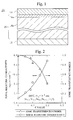
- FIG. 2 The relationship between the percentage of B2 which are transition metal elements doped in the B site, and the total electric conductivity and the ionic transference number, in 5 components multiple oxide ionic conductor (e.g. La 0.8 Sr 0.2 Ga 0.8 Mg 0.2-c Co c O 3 ) is shown in FIG. 2.
- Total electric conductivity shown in FIG. 2 contains both the ionic and electronic components. It is clear that this lanthanide-gallate oxide has a high oxide ionic conductivity for a wide range of temperatures, which higher than that of stabilized zirconia, and also has high heat resistance. Furthermore, it is also confirmed that lanthanide-gallate oxide has a high ionic transference number at all oxygen partial pressures from the oxygen atmosphere to the hydrogen atmosphere.
- the ionic transference number of the solid electrolyte comprising the solid electrolyte layer should ideally be 1.0. In other words, it is preferable that the total electric conductivity of the solid electrolyte is entirely due to the oxide ions, and that the electronic conduction is not possible between the air electrode layer and the fuel electrode layer at all.
- an added amount of a transition metal (B2 z ), namely Co is needed to cause a decrease, as shown in FIG. 2.
- the thickness of the solid electrolyte layer 3 significantly decreases, the total electric conductivity increases, and the problem may be solved.
- the partition wall function which functions so as to prevent direct contact between the fuel gas and air, may be decreased. Therefore, there is a limit in the thickness of the solid electrolyte layer.
- one of the objectives of the present invention is to provide a solid oxide fuel cell which has an improved efficiency achieved by a solid electrolyte layer having improved ionic conductivity, while maintaining the partition wall function.
- the present invention provides a solid oxide fuel cell comprising an air electrode layer, a fuel electrode layer, and a solid electrolyte layer interposed between the air electrode layer and the fuel electrode layer, wherein the solid electrolyte layer comprises a first electrolyte layer which is made of a lanthanide-gallate oxide with a first ionic transference number and a first total electric conductivity, and a second electrolyte layer which is made of a lanthanide-gallate oxide with a second ionic transference number smaller than the first ionic transference number and a second total electric conductivity larger than the first total electric conductivity; the air electrode layer is laminated onto one side of the solid electrolyte layer; and the fuel electrode layer is laminated onto the other side of the solid electrolyte layer.
- the solid electrolyte layer made of a lanthanide-gallate oxide has a total electric conductivity larger than that of the conventional solid electrolyte layer made of YSZ. Therefore, as for the solid oxide fuel cell of the present invention, the operating temperatures can be lower than the conventional ones.
- oxide ions which are ionized in the vicinity of the interface between the air electrode layer and the solid electrolyte layer, diffuse toward the fuel electrode layer through the first and the second electrolyte layers. Then, the oxide ions discharge electrons to the fuel electrode layer. The discharged electrons flow between the fuel electrode layer and the air electrode layer as an electric current. Thereby, the fuel cell acts as a power generator. Moreover, a portion of the electrons, which are discharged in the fuel electrode layer, try to return to the second electrolyte layer and diffuse toward the air electrode layer. However, the first electrolyte layer is positioned between the second electrolyte layer and the air electrode layer.
- the first electrolyte layer contains a small amount of Co and the ionic transference number is relatively high; therefore, the electronic conductivity is extremely small. Therefore, the electrons can hardly be conducted in the first electrolyte layer. Then, the electrons move in the solid electrolyte layer toward the fuel electrode layer again, and finally reach to the fuel electrode layer. After that, the electrons flow between the fuel electrode layer and the air electrode layer as an electric current, similar to the electrons explained above. As a result, the ionic conductivity of the solid electrolyte layer can be remarkably improved, and the efficiency of the solid oxide fuel cell of the present invention can be improved.
- La is the most preferable among lanthanide (Ln). That is, La is more preferable than Ce, Pr, Nd, Pm, Sm, Eu, Gd, Tb, Dy, Ho, Er, Tm, Yb, and Lu.
- the lanthanide-gallate oxide is the most preferable, which is represented by Ln 1-a A a Ga 1-(b+c) B b Co c O 3 , wherein Ln is lanthanide rare earth metals, A is one or more kinds of Sr, Ca, and Ba; B is one or more kinds of Mg, Al, and In; a is in a range from 0.05 to 0.3; b is in a range from 0 to 0.3; c is in a range from 0 to 0.2; and (b+c) is in a range from 0.025 to 0.3.
- Ln is lanthanide rare earth metals
- A is one or more kinds of Sr, Ca, and Ba
- B is one or more kinds of Mg, Al, and In
- a is in a range from 0.05 to 0.3
- b is in a range from 0 to 0.3
- c is in a range from 0 to 0.2
- (b+c) is in a range from 0.025
- a compound represented by the following general formula (1) is the most preferable.
- La 1-a A a Ga 1-(b+c) B b Co c O 3 (1) wherein A is one or more kinds of Sr, Ca, or Ba; B is one or more kinds of Mg, Al, and In; a is in a range from 0.05 to 0.3; b is in a range from 0 to 0.3; c is in a range from 0 to 0.2; and (b+c) is in a range from 0.025 to 0.3.
- the amount of Co in the first electrolyte layer is preferably 0 or 80 % or less than the amount of Co in the second electrolyte layer.
- the ionic transference number and the total electric conductivity of the lanthanum-gallate oxide depend on the c value.
- the percentage of the ionic conductivity with respect to the total electric conductivity increases. Therefore, when the compound represented by general formula (1) is used as the lanthanide-gallate oxide, and the amount of Co in the first electrolyte layer is adjusted so as to be 0 or 80 % or less with respect to the amount of Co in the second electrolyte layer, the first electrolyte layer having the ionic conductivity larger than that of the second electrolyte layer can be easily formed.
- the thickness of the solid electrolyte layer comprising the first and second electrolyte layers is preferably in a range from 1 to 500 ⁇ m (more preferably in a range from 5 to 100 ⁇ m).
- the thickness of the solid electrolyte layer is less than 1 ⁇ m, the partition wall function may be lost.
- the total electric conductivity decreases; therefore, the efficiency of the solid oxide fuel cell also decreases.
- the percentage of the thickness of the first electrolyte layer with respect to the thickness of the second electrolyte layer is preferably in a range from 1 to 20 % (more preferably in a range from 3 to 10 %).
- the percentage of the thickness of the first electrolyte layer with respect to the thickness of the second electrolyte layer is less than 1 %, pin-holes may be generated in the first electrolyte layer.
- the total electrical conductivity of the solid electrolyte layer decreases.
- the total electric conductivity of the first electrolyte layer becomes less than that of the second electrolyte layer.
- the percentage of the thickness of the first electrolyte layer with respect to the thickness of the second electrolyte layer is set in a range from 1 to 20 %; the decrease in the total electric conductivity of the first electrolyte layer can be prevented. Therefore, the total electric conductivity of the solid electrolyte layer comprising the first and second electrolyte layers can be optimized.
- both the first and second electrolyte layers act as a partition wall; therefore, the partition wall function of the solid electrolyte layer would not be lost even when the thickness of the first electrolyte layer decreases.
- the amount of Co preferably decreases gradually from the second electrolyte layer to the first electrolyte layer in the vicinity of the interface between the first electrolyte layer and the second electrolyte layer. Since, the first electrolyte layer and the second electrolyte layer can be formed simultaneously, the solid electrolyte layer can be produced easily with low cost, compared with the method in which the first and second electrolyte layers are made separately, and then laminated. Moreover, the first and second electrolyte layers can be produced simultaneously by placing an alumina setter onto a green sheet having one composition when the green sheet is sintered.
- the second electrolyte layer can be laminated onto the air electrode layer and the first electrolyte layer can be laminated onto the fuel electrode layer in the solid oxide fuel cell of the present invention.
- the lanthanum-gallate oxide is exemplified as the lanthanide-gallate oxides.
- a solid oxide fuel cell 11 comprises a fuel electrode layer 13 which is in contact with the fuel gas e.g. hydrogen, an air electrode layer 14 which is made of a porous material in contact with air, and a solid electrolyte layer 16 which is interposed between the fuel electrode layer 13 and the air electrode layer 14.
- the fuel gas e.g. hydrogen
- the air electrode layer 14 which is made of a porous material in contact with air
- a solid electrolyte layer 16 which is interposed between the fuel electrode layer 13 and the air electrode layer 14.
- the fuel electrode layer 13 becomes a negative electrode; and the air electrode layer 14 becomes a positive electrode. Thereby electric current flows between these electrodes when both electrodes are in electrical contact.
- the solid electrolyte layer 16 further comprises a first electrolyte layer 16a and a second electrolyte layer 16b. These first and second electrolyte layers 16a and 16b are made of a lanthanum-gallate oxide.
- the solid electrolyte layer 16 is formed by laminating the first electrolyte layer 16a with the second electrolyte layer 16b, which are produced separately.
- the solid electrolyte layer 16 can also be produced by partially removing Co from the surface layer of a precursor of the solid electrolyte layer 16.
- the first and second electrolyte layers 16a and 16b are simultaneously produced by this method.
- the solid electrolyte layer 16 can be produced easily, and cheaply, compared to the above method in which the first and second electrolyte layers are produced separately, and then laminated.
- the first and second electrolyte layers 16a and 16b are made of lanthanum-gallate oxide represented by a general formula (1): La 1-a A a Ga 1-(b+c) B b Co c O 3 .
- A is one or more kinds of Sr, Ca, and Ba; and B is one or more kinds of Mg, Al, and In.
- the solid electrolyte layer 16 is made of a lanthanide gallate oxide which is a multiple oxide of 5 elements (Ln + A + Ga + B + Co) obtained by doping 3 kinds of elements containing an alkaline earth metal (A), a non-transition metal (B), and a transition metal (Co) into a lanthanide-gallate (LnGaO 3-d ).
- the lanthanum-gallate oxide represented by the general formula (1) has a perovskite crystal structure, which is represented by ABO 3-d , and the A site is occupied by the A element, and the B site is occupied by Ga, the B element and Co.
- the A site and the B site are occupied with divalent metals.
- oxygen vacancies are generated.
- the oxide ionic conductivity is generated due to the oxygen vacancies.
- oxygen atoms decrease in proportion to the number of oxygen vacancies.
- a indicates the percentage of the A element and should be in the range from 0.05 to 0.3, (preferably in a range from 0.10 to 0.25); b indicates the percentage of the B element and should be in the range from 0 to 0.3 (preferably in a range from 0.05 to 0.2); c indicates the percentage of Co and is in a range from 0 to 0.2 (preferably in a range from 0.03 to 0.1); and (b+c) is in a range from 0.025 to 0.30 (preferably in a range from 0.10 to 0.25).
- the A element is preferably Sr, and the B element is preferably Mg.
- the atom ratio of oxygen is 3 in general formula (1).
- the atom ratio of oxygen is practically less than 3.
- the number of oxygen vacancies vary depending on the variations A and B elements, the preparation conditions, etc..
- the atom ratio of oxygen is shown as 3 in the general formula (1).
- the lanthanum-gallate oxide represented by general formula (1) is chemically stable under oxidizing atmosphere and reducing atmosphere at high temperatures, and the electric conductivity does not remarkably change. Therefore, the lanthanum-gallate oxide represented by the general formula (1) is suitable for the material of the solid electrolyte layer 16 of the solid oxide fuel cell 11.
- the electric conductivity of the lanthanum-gallate oxide represented by the general formula (1) is higher than that of YSZ at all temperatures.
- the fuel cell comprising the solid electrolyte layer made of YSZ cannot be operated at 600 to 800°C, because the electric conductivity of YSZ is low.
- the fuel cell comprising the solid electrolyte layer 16 made of the lanthanum-gallate oxide represented by the general formula (1) can be used sufficiently at such temperatures.
- the fuel cell is stable and can be operated at high temperatures greater than 1000°C.
- the total electric conductivity of the material represented by general formula (1) increases in proportion to the c value which is the atom ratio of Co. This is due to Co being a transition metal. That is, when the valence of Co varies, an n or p type electronic conduction is generated. Therefore, when a larger amount of Co is introduced to the material represented by the general formula (1), the electronic conductivity increases, and thereby the total electric conductivity also increases.
- the percentage of the oxide ionic conductivity with respect to the total electric conductivity decreases. Namely, the ionic transference number decreases. Concretely, the ionic transference number of the 5 component multi oxide having a c value being 0.15 or less is 0.7 or greater.
- the ionic transference number is 0.9 or greater.
- the ionic transference number is small, 0.7 or less.
- the multi oxide can act as an electron-ion multi conductor, namely an oxide ionic mixed conductor.
- a 4 components multi oxide in which Mg being the B element is entirely substituted for Co, has an ionic transference number of only about 0.3; however, it functions as an oxide ionic mixed conductor, therefore, it has the highest electric conductivity.
- the first and second electrolyte layers 16a and 16b are made of the lanthanum-gallate oxide represented by the general formula (1). However, the amount of Co in the first electrolyte layer 16a is less than that in the second electrolyte layer 16b. The ionic transference number of the first electrolyte layer 16a is larger than that of the second electrolyte layer 16b. Moreover, the electric conductivity of the second electrolyte layer 16b is larger than that of the first electrolyte layer 16a.
- the solid electrolyte layer 16 is produced by laminating green sheets of the first and second electrolyte layers 16a and 16b using the thermo-compression bonding method. Moreover, the solid electrolyte layer 16 can also be produced by sintering the first electrolyte layer 16a and coating a slurry for the second electrolyte layer 16b onto the first electrolyte layer 16a using a slurry coating method or a screen printing method, followed by resintering. Of course, the solid electrolyte layer 16 can also be produced by sintering the second electrolyte layer 16b and coating a slurry for the first electrolyte layer 16a onto the second electrolyte layer 16b and then resintering both.
- the method in which the first and second electrolyte layers 16a and 16b sintered together is preferable simply, because the number of sintering steps is fewer.
- the first and second electrolyte layers 16a and 16b can be produced by either a compression molding method, or a hydrostatic molding method, or a casting method, instead of the doctor blade method.
- the first or second electrolyte layer 16a or 16b can be directly formed onto the second or first electrolyte layer 16b or 16a by a slurry coating method, a doctor blade coating method, etc..
- first or second electrolyte layer 16a or 16b can also be directly formed onto the sintered second or first electrolyte layer 16b or 16a by a slurry coating method, a screen printing method, a spraying method, etc..
- the first and second electrolyte layers 16a and 16b are integrated by an appropriate heat treatment.
- the heat treatment conditions are not limited; however, the heat treatment temperature is preferably in a range from 1100 to 1500°C. When the heat treatment temperature is in the above given range, the treatment time may be in a range from 1 to 100 hours.
- the heat treatment is sufficiently carried out in air, but can also be carried out in an inert gas atmosphere.
- the first and second electrolyte layers 16a and 16b can be produced by arranging an alumina setter onto a green sheet having one chemical composition when the green sheet is sintered.
- Co in the green sheet diffuses towards the alumina setter.
- an upper layer of the green sheet containing a small amount of Co becomes the first electrolyte layer 16a
- the remainder of the green sheet becomes the second electrolyte layer 16b.
- the amount of Co in the first electrolyte layer 16a and the thickness of the first electrolyte layer 16a can be adjusted by changing the sintering temperature or the sintering time.
- the thickness of the first electrolyte layer 16a is in a range from 1 to 20 % with respect to the thickness of the second electrolyte layer 16b.
- the thickness of the solid electrolyte layer 16 is in a range from 1 to 500 ⁇ m.
- the solid oxide fuel cell 11 is produced by laminating the air electrode layer 14 onto the first electrolyte layer 16a, and laminating the fuel electrode layer 13 onto the second electrolyte layer 16b.
- the solid oxide fuel cell which is not shown in the figures, can also be formed. This type of solid oxide fuel cell also has an excellent power generation characteristic.
- the thickness of the first electrolyte layer 16a is very small, specifically it is in a range from 1 to 20 % with respect to the thickness of the second electrolyte layer 16b. Thereby, the oxide ions can travel in the first electrolyte layer 16a toward the second electrolyte layer 16b.
- the second electrolyte layer 16b contains more Co than the first electrolyte layer 16a, and the total electric conductivity of the second electrolyte layer 16b is larger than that of the first electrolyte layer 16a. Therefore, although the second electrolyte layer 16b is thick, the oxide ions diffuse through the second electrolyte layer 16b and relatively easily reach in the vicinity of the interface between the fuel electrode layer 13 and the second electrolyte layer 16b. Then, the oxide ions react with the fuel gas, generate a reaction product, such as H 2 O and CO 2 , and discharge electrons to the fuel electrode layer 4. The discharged electrons flow between the fuel electrode layer 13 and the air electrode layer 14 as an electric current. Thereby, the fuel cell 11 acts as a electric power generator.
- the total electric conductivity of the second electrolyte layer 16b is large; therefore, a portion of the electrons, which are discharged in the fuel electrode layer 13, try to return to the second electrolyte layer 16b and travel toward the air electrode layer 14.
- the first electrolyte layer 16a is positioned between the second electrolyte layer 16b and the air electrode layer 14.
- the first electrolyte layer 16a contains a small amount of Co and the ionic transference number is relatively high; therefore, the electronic conductivity is extremely small. Therefore, the electrons can hardly travel in the first electrolyte layer 16a. Then, the electrons travel in the solid electrolyte layer 16 toward the fuel electrode layer 13 again, and finally reach the fuel electrode layer 13. After that, the electrons flow between the fuel electrode layer 13 and the air electrode layer 14 as an electric current, as the same way explained earlier.
- the lanthanum-gallate oxides are exemplified as the lanthanide-gallate oxides in the above explanation.
- the lanthanide-gallate oxides beside the lanthanum-gallate oxide can be used in the present invention.
- the air electrode layer 14 was made of an oxide ionic mixed conductor represented by Sm 0.5 Sr 0.5 CoO 3-d .
- the fuel electrode layer 13 was made of a mixture containing Ni and a compound represented by Ce 0.8 Sm 0.2 O 2 .
- the first electrolyte layer 16a was made of a compound represented by La 0.75 Sr 0.15 Ga 0.775 Mg 0.125 Co 0.1 O 3-d .
- the second electrolyte layer 16b was made of an oxide ionic mixed conductor represented by La 0.8 Sr 0.2 Ga 0.8 Mg 0.15 Co 0.05 O 3-d .
- the solid electrolyte layer 16 was formed by the following steps. First, oxide powder materials were mixed to obtain the above compositions of the first and second electrolyte layers 16a and 16b. Then, the oxide mixtures were pre-sintered in a range from 900 to 1200°C. Slurries were prepared by crushing the obtained pre-sintered products by a ball mill, and adding binders and solvents to them.
- Laminated green sheets of the first and second electrolyte layers 16a and 16b were produced by coating the slurries by a doctor blade method. Then, the green sheets were sufficiently dried in air, and sintered in a range from 1300 to 1500 °C. Thereby, the solid electrolyte layer 16 was produced.
- the thickness of the solid electrolyte layer 16 was 100 ⁇ m.
- the thickness of the first electrolyte layer 16a was 5 ⁇ m, and is 5 % with respect to the thickness of the second electrolyte layer 16b.
- the fuel cell 11 was formed by sintering the fuel electrode layer 13 onto the second electrolyte layer 16b in a range from 1000 to 1200°C, and sintering the air electrode layer 14 onto the first electrolyte layer 16a in a range from 800 to 1100°C.
- the first and second electrolyte layers 16a and 16b were produced by coating the alumina setter on a green sheet having the composition represented by La 0.9 Sr 0.1 Ga 0.8 Mg 0.12 Co 0.08 O 3-d and sintering.
- the first electrolyte layer 16a was formed at the surface layer of the green sheet, which was coated with the alumina setter.
- the remainder of the green sheet was the second electrolyte layer 16b.
- the thickness of the solid electrolyte layer 16 comprising the first and second electrolyte layers 16a and 16b was 100 ⁇ m.
- the fuel cell 11 was formed using the solid electrolyte layer 16, similar to Example 1.
- the first electrolyte layer 16a having a thickness of 15 ⁇ m was formed in the upper surface of the solid electrolyte layer 16.
- the remainder of the solid electrolyte layer 16 was the second electrolyte layer 16b.
- a fuel cell 11 was produced in a manner identical to that of Example 1, except the fuel electrode layer 13 was sintered onto the first electrolyte layer 16a, and the air electrode layer 14 was sintered onto the second electrolyte layer 16b.
- a comparative fuel cell was produced in a manner identical to that of Example 1, except the first electrolyte layer 16a. Moreover, the thickness of the solid electrolyte layer, which corresponds to the second electrolyte layer 16b, was 100 ⁇ m, similar to the Example 1.
- a comparative fuel cell was produced in a manner identical to that of Example 1, except the second electrolyte layer 16b. Moreover, the thickness of the solid electrolyte layer, which corresponds to the first electrolyte layer 16a, was 100 ⁇ m, similar to Example 1.
- a comparative fuel cell was produced in a manner identical to that of Example 1, provided that the solid electrolyte layer 16 was made of YSZ. Moreover, the thickness of the solid electrolyte layer made of YSZ was 100 ⁇ m, similar to Example 1.
- the performance of the fuel cells produced in Comparative Examples 1 and 2, which comprise the solid electrolyte layer 16 made of the lanthanum-gallate oxide is inferior to that of the fuel cells produced in Examples 1 to 3. This may be caused due to the decrease of the total electric conductivity of the solid electrolyte layer 16 itself in the fuel cell produced in Comparative Example 2.
- the percentage of the ionic conductivity with respect to the total electric conductivity is small, therefore, the generation performance is inferior to that of the fuel cells produced in Examples 1 to 3.
Landscapes
- Engineering & Computer Science (AREA)
- Manufacturing & Machinery (AREA)
- Life Sciences & Earth Sciences (AREA)
- Sustainable Development (AREA)
- Sustainable Energy (AREA)
- Chemical & Material Sciences (AREA)
- Chemical Kinetics & Catalysis (AREA)
- Electrochemistry (AREA)
- General Chemical & Material Sciences (AREA)
- Fuel Cell (AREA)
- Conductive Materials (AREA)
Applications Claiming Priority (2)
| Application Number | Priority Date | Filing Date | Title |
|---|---|---|---|
| JP2000193750 | 2000-06-28 | ||
| JP2000193750A JP4517466B2 (ja) | 2000-06-28 | 2000-06-28 | 固体酸化物型燃料電池 |
Publications (2)
| Publication Number | Publication Date |
|---|---|
| EP1168478A2 true EP1168478A2 (fr) | 2002-01-02 |
| EP1168478A3 EP1168478A3 (fr) | 2004-12-15 |
Family
ID=18692690
Family Applications (1)
| Application Number | Title | Priority Date | Filing Date |
|---|---|---|---|
| EP01114836A Withdrawn EP1168478A3 (fr) | 2000-06-28 | 2001-06-28 | Pile à combustible à électrolyte solide d'oxydes |
Country Status (4)
| Country | Link |
|---|---|
| US (1) | US7033690B1 (fr) |
| EP (1) | EP1168478A3 (fr) |
| JP (1) | JP4517466B2 (fr) |
| AU (1) | AU5407901A (fr) |
Cited By (4)
| Publication number | Priority date | Publication date | Assignee | Title |
|---|---|---|---|---|
| EP1531511A2 (fr) | 2003-11-12 | 2005-05-18 | HONDA MOTOR CO., Ltd. | Arrangement des électrodes et de l'électrolyte et son procedé de production |
| EP1482584A4 (fr) * | 2002-03-04 | 2007-10-10 | Mitsubishi Materials Corp | Electrode pour pile a combustible en oxyde solide et pile a combustible de ce type |
| WO2009005841A1 (fr) * | 2007-07-05 | 2009-01-08 | The Board Of Trustees Of The Leland Stanford Junior University | Interfaces électrode/électrolyte dans des piles à combustible à oxyde solide |
| WO2015023688A1 (fr) * | 2013-08-14 | 2015-02-19 | Board Of Regents, The University Of Texas System | Conducteurs d'ions oxygène, composites et dispositifs associés |
Families Citing this family (19)
| Publication number | Priority date | Publication date | Assignee | Title |
|---|---|---|---|---|
| JP4211254B2 (ja) | 2001-12-04 | 2009-01-21 | 関西電力株式会社 | 固体酸化物形燃料電池 |
| JP2005085522A (ja) * | 2003-09-05 | 2005-03-31 | Mitsubishi Materials Corp | 支持膜式固体酸化物形燃料電池 |
| JP4923407B2 (ja) * | 2004-01-16 | 2012-04-25 | 三菱マテリアル株式会社 | 固体酸化物形燃料電池の製造方法 |
| US7462412B2 (en) | 2005-03-04 | 2008-12-09 | Toto Ltd. | Solid oxide fuel cell |
| US7569292B2 (en) | 2005-03-04 | 2009-08-04 | Toto Ltd. | Solid oxide fuel cell |
| JP4933757B2 (ja) * | 2005-09-05 | 2012-05-16 | 株式会社ノリタケカンパニーリミテド | 非電子伝導性組成傾斜型固体電解質膜 |
| CN101558520B (zh) | 2006-10-26 | 2012-12-19 | Toto株式会社 | 固体氧化物型燃料电池 |
| US7851103B2 (en) | 2006-10-26 | 2010-12-14 | Toto Ltd. | Solid oxide fuel cell with lanthanum-gallate oxide and having high output performance |
| JP5196216B2 (ja) * | 2006-10-27 | 2013-05-15 | 独立行政法人産業技術総合研究所 | 電気化学リアクター |
| US8148031B2 (en) * | 2008-11-13 | 2012-04-03 | College Of William And Mary | Solid oxide proton conductor system and method of operating same for enhanced proton transport |
| WO2012061965A1 (fr) * | 2010-11-08 | 2012-05-18 | 中国科学院宁波材料技术与工程研究所 | Membrane électrolyte, dispositif électrochimique et pile à combustible à oxyde solide (sofc) |
| CN103460476B (zh) | 2011-04-01 | 2016-11-23 | Toto株式会社 | 铈系复合氧化物的制造方法、固体氧化物型燃料电池单电池及燃料电池系统 |
| JP5936045B2 (ja) * | 2011-04-12 | 2016-06-15 | Toto株式会社 | 固体酸化物形燃料電池 |
| JP5553187B2 (ja) | 2012-09-14 | 2014-07-16 | Toto株式会社 | 固体酸化物形燃料電池セル及びその製造方法 |
| JP6194698B2 (ja) | 2012-09-14 | 2017-09-13 | Toto株式会社 | 固体酸化物形燃料電池セル及びその製造方法 |
| JP6156778B2 (ja) | 2012-09-28 | 2017-07-05 | Toto株式会社 | 固体酸化物形燃料電池セル |
| JP6332610B2 (ja) | 2013-03-28 | 2018-05-30 | Toto株式会社 | 固体酸化物形燃料電池セル及びその製造方法 |
| JP2014209477A (ja) | 2013-03-28 | 2014-11-06 | Toto株式会社 | 固体酸化物形燃料電池セル及びその製造方法 |
| TWI642229B (zh) * | 2015-12-02 | 2018-11-21 | 國立臺北科技大學 | Ceramic battery structure |
Family Cites Families (6)
| Publication number | Priority date | Publication date | Assignee | Title |
|---|---|---|---|---|
| JP3259756B2 (ja) * | 1995-08-25 | 2002-02-25 | 日本電信電話株式会社 | 固体燃料電池用多層型固体電解質 |
| JP3218555B2 (ja) * | 1995-09-18 | 2001-10-15 | 日本電信電話株式会社 | 保護層付きセリア系固体電解質 |
| JP4178610B2 (ja) * | 1997-08-29 | 2008-11-12 | 祐作 滝田 | 酸化物イオン伝導体とその用途 |
| JP4119511B2 (ja) | 1998-02-06 | 2008-07-16 | 東京瓦斯株式会社 | 酸化物イオン導電性材料 |
| JP3667112B2 (ja) * | 1998-10-05 | 2005-07-06 | 日本特殊陶業株式会社 | LaGaO3系粉末の製造方法及びLaGaO3系焼結体の製造方法 |
| JP3777903B2 (ja) * | 1998-10-14 | 2006-05-24 | 三菱マテリアル株式会社 | 電極−電解質間に傾斜組成を持つ固体酸化物型燃料電池 |
-
2000
- 2000-06-28 JP JP2000193750A patent/JP4517466B2/ja not_active Expired - Lifetime
-
2001
- 2001-06-27 US US09/891,501 patent/US7033690B1/en not_active Expired - Lifetime
- 2001-06-27 AU AU54079/01A patent/AU5407901A/en not_active Abandoned
- 2001-06-28 EP EP01114836A patent/EP1168478A3/fr not_active Withdrawn
Cited By (7)
| Publication number | Priority date | Publication date | Assignee | Title |
|---|---|---|---|---|
| EP1482584A4 (fr) * | 2002-03-04 | 2007-10-10 | Mitsubishi Materials Corp | Electrode pour pile a combustible en oxyde solide et pile a combustible de ce type |
| EP1531511A2 (fr) | 2003-11-12 | 2005-05-18 | HONDA MOTOR CO., Ltd. | Arrangement des électrodes et de l'électrolyte et son procedé de production |
| EP1531511A3 (fr) * | 2003-11-12 | 2008-05-21 | HONDA MOTOR CO., Ltd. | Arrangement des électrodes et de l'électrolyte et son procedé de production |
| US7601447B2 (en) | 2003-11-12 | 2009-10-13 | Honda Motor Co., Ltd. | Electrolyte-electrode assembly comprising an isotropic layer |
| WO2009005841A1 (fr) * | 2007-07-05 | 2009-01-08 | The Board Of Trustees Of The Leland Stanford Junior University | Interfaces électrode/électrolyte dans des piles à combustible à oxyde solide |
| WO2015023688A1 (fr) * | 2013-08-14 | 2015-02-19 | Board Of Regents, The University Of Texas System | Conducteurs d'ions oxygène, composites et dispositifs associés |
| US9093692B2 (en) | 2013-08-14 | 2015-07-28 | Board Of Regents, The University Of Texas System | Oxide-ion conductors and related composites and devices |
Also Published As
| Publication number | Publication date |
|---|---|
| US7033690B1 (en) | 2006-04-25 |
| JP4517466B2 (ja) | 2010-08-04 |
| JP2002015756A (ja) | 2002-01-18 |
| EP1168478A3 (fr) | 2004-12-15 |
| AU5407901A (en) | 2002-01-03 |
Similar Documents
| Publication | Publication Date | Title |
|---|---|---|
| US7033690B1 (en) | Solid oxide fuel cell | |
| EP2061108B1 (fr) | Cellule de pile à combustible, pile de cellules de pile à combustible et pile à combustible | |
| US7351487B2 (en) | Fuel cell | |
| JP3777903B2 (ja) | 電極−電解質間に傾斜組成を持つ固体酸化物型燃料電池 | |
| KR101175599B1 (ko) | 인터커넥터용 재료, 셀간 분리 구조체 및 고체 전해질형 연료 전지 | |
| US5143801A (en) | Solid oxide fuel cells, and air electrode and electrical interconnection materials therefor | |
| EP2355217B1 (fr) | Elément de batterie à combustible, module de batterie à combustible, dispositif de batterie à combustible et procédé de fabrication d un élément de batterie à combustible | |
| US7914941B2 (en) | Solid oxide fuel cell and manufacturing method thereof | |
| KR20160048809A (ko) | 금속지지체형 고체산화물 연료전지 | |
| JPWO2018159584A1 (ja) | プロトン伝導性電解質 | |
| KR20140088899A (ko) | 고체 산화물 연료전지 상호접속 전지 | |
| EP1528615B1 (fr) | Pile à combustible | |
| EP3002813B1 (fr) | Piles à combustibles oxyde solides | |
| CN104518231A (zh) | 固体氧化物型燃料电池电堆 | |
| JP3456436B2 (ja) | 固体酸化物型燃料電池 | |
| JP4828104B2 (ja) | 燃料電池セル | |
| JPH1074528A (ja) | 固体電解質型燃料電池およびその製造方法 | |
| CN100537470C (zh) | 离子导体 | |
| JP4579527B2 (ja) | 燃料電池セル、燃料電池及び燃料電池セルの製法 | |
| EP3002811B1 (fr) | Pile a combustible d'oxyde solide | |
| JP2005108719A (ja) | 固体酸化物型燃料電池 | |
| KR20250054445A (ko) | 치밀질 금속 산화물층, 이를 포함하는 고체 산화물 연료전지 및 치밀질 금속 산화물층의 제조 방법 | |
| KR20240063501A (ko) | 고체산화물 연료전지용 공기극 소재 및 이를 포함하는 고체산화물 연료전지 |
Legal Events
| Date | Code | Title | Description |
|---|---|---|---|
| PUAI | Public reference made under article 153(3) epc to a published international application that has entered the european phase |
Free format text: ORIGINAL CODE: 0009012 |
|
| AK | Designated contracting states |
Kind code of ref document: A2 Designated state(s): AT BE CH CY DE DK ES FI FR GB GR IE IT LI LU MC NL PT SE TR |
|
| AX | Request for extension of the european patent |
Free format text: AL;LT;LV;MK;RO;SI |
|
| RIN1 | Information on inventor provided before grant (corrected) |
Inventor name: TAMOU, YOSHITAKA , C/O MITSUBISHI RES. INSTITUT Inventor name: AKIKUSA, JUN, C/OMITSUBISHI MAT. CORPORATION |
|
| PUAL | Search report despatched |
Free format text: ORIGINAL CODE: 0009013 |
|
| AK | Designated contracting states |
Kind code of ref document: A3 Designated state(s): AT BE CH CY DE DK ES FI FR GB GR IE IT LI LU MC NL PT SE TR |
|
| AX | Request for extension of the european patent |
Extension state: AL LT LV MK RO SI |
|
| 17P | Request for examination filed |
Effective date: 20050610 |
|
| AKX | Designation fees paid |
Designated state(s): DE FR |
|
| 17Q | First examination report despatched |
Effective date: 20060706 |
|
| STAA | Information on the status of an ep patent application or granted ep patent |
Free format text: STATUS: THE APPLICATION IS DEEMED TO BE WITHDRAWN |
|
| 18D | Application deemed to be withdrawn |
Effective date: 20061117 |