EP1168530A2 - Amplificateur Raman - Google Patents
Amplificateur Raman Download PDFInfo
- Publication number
- EP1168530A2 EP1168530A2 EP01115122A EP01115122A EP1168530A2 EP 1168530 A2 EP1168530 A2 EP 1168530A2 EP 01115122 A EP01115122 A EP 01115122A EP 01115122 A EP01115122 A EP 01115122A EP 1168530 A2 EP1168530 A2 EP 1168530A2
- Authority
- EP
- European Patent Office
- Prior art keywords
- optical fiber
- optical
- raman
- fiber
- optical signal
- Prior art date
- Legal status (The legal status is an assumption and is not a legal conclusion. Google has not performed a legal analysis and makes no representation as to the accuracy of the status listed.)
- Granted
Links
Images




Classifications
-
- H—ELECTRICITY
- H01—ELECTRIC ELEMENTS
- H01S—DEVICES USING THE PROCESS OF LIGHT AMPLIFICATION BY STIMULATED EMISSION OF RADIATION [LASER] TO AMPLIFY OR GENERATE LIGHT; DEVICES USING STIMULATED EMISSION OF ELECTROMAGNETIC RADIATION IN WAVE RANGES OTHER THAN OPTICAL
- H01S3/00—Lasers, i.e. devices using stimulated emission of electromagnetic radiation in the infrared, visible or ultraviolet wave range
- H01S3/30—Lasers, i.e. devices using stimulated emission of electromagnetic radiation in the infrared, visible or ultraviolet wave range using scattering effects, e.g. stimulated Brillouin or Raman effects
- H01S3/302—Lasers, i.e. devices using stimulated emission of electromagnetic radiation in the infrared, visible or ultraviolet wave range using scattering effects, e.g. stimulated Brillouin or Raman effects in an optical fibre
Definitions
- This invention relates to a Raman amplifier.
- a fiber Raman amplifier to amplify the optical signal on an optical transmission line is effective, and thereby receiving sensitivity and the SNR (the signal-to-noise ratio) are improved.
- SNR the signal-to-noise ratio
- Fiber Raman amplifiers there are two kinds of methods of pumping.
- One is a forward pumping method in which the high-output pumping light to produce Raman amplification on an optical transmission line enters onto the optical transmission line in the same direction with that of signal propagation, namely from the front
- the other is a backward pumping method in which the pumping light enters onto the optical transmission line in the opposite direction to that of the optical signal propagation, namely from the back.
- the Raman amplification is caused by nonlinear effects of an optical fiber. Accordingly, to increase the Raman gain, it is necessary to increase pumping power and/or employ an optical fiber with large nonlinear effects. On condition that optical fibers are of the same material and configuration, the one having the smallest core diameter has the largest nonlinear effect.
- an optical fiber of a large core diameter is used for the first half part of an optical transmission line where power of the optical signal is large, and an optical fiber of a small core diameter, i.e. an optical fiber of large Raman gain coefficient, is used for the latter half part of the optical fiber where the power of the optical signal is small.
- the pumping light is introduced into the latter optical fiber from the back in the opposite direction from that of optical signal propagation.
- the weak optical signal is amplified at the latter half part of the optical transmission line, and accordingly the decrease, of the optical signal level is moderated or the optical signal level is increased.
- Another object of the present invention is to provide a Raman amplifier to offer the satisfactory SNR while keeping the necessary Raman gain.
- a Raman amplifier consists of a first optical fiber to propagate the optical signal, a second optical fiber to which the optical signal output from the first optical fiber enters, the pumping light source to generate the pumping light for Raman amplification, and an optical introducer to introduce the output light from the pumping light source into the second optical fiber from the output side of the optical signal, the Raman amplifier characterized in that the ratio of the Raman gain coefficient of the second optical fiber to that of the first optical fiber is 1/1.08 or less.
- Raman gain increases proportional to the intensity (mW or W) of the pumping light, and the Raman gain and the optical noise power caused by the Raman gain are proportional.
- the optical noise amount generated by the same Raman gain is unchanged.
- the optical noise at the receiver differs according to locations of the occurrence.
- the optical noises generated at the points near to the receiver are detected as the optical noises of almost the same level.
- the optical noise detected at the receiver is reduced according to the shifted length toward the transmitter side. Therefore, the more the location of the Raman gain occurrence shifts to the transmitter side, the more the SNR at the receiver is improved.
- FIG. 1 shows a schematic block diagram of an example according to the invention.
- Reference numeral 10 denotes a dispersion shifted fiber in which the zero dispersion wavelength is shifted to the 1.55 ⁇ m band
- 12 denotes a single mode optical fiber having the effective core area of approximately 100 ⁇ m 2 which is larger than that of the optical fiber 10.
- the core parts of the optical fibers 10 and 12 are schematically illustrated.
- the optical signal enters the dispersion shifted fiber 10 first, propagates on the fiber, and then enters the single mode optical fiber 12.
- An optical coupler 14 is disposed on the emission end for the optical signal of the single mode optical fiber 12.
- a laser diode 16 outputs the 1,455 nm laser light as the pumping light source.
- the output light from the laser diode 16 is introduced into the optical fiber 12 from the back, namely in the opposite direction from that of the optical signal propagation, by the optical coupler 14.
- the optical signal amplified in the optical fibers 10 and 12 as explained later enters the following optical component (for example, an optical fiber or a photodetector), which is not illustrated, through the optical coupler 14.
- the pumping light introduced into the optical fiber 12 by the optical coupler 14 amplifies the optical signal as it gradually attenuates while propagating on the optical fiber 12.
- an optical fiber having a small Raman gain coefficient is used as the optical fiber 12 so that the location at which the Raman amplification occurs is to shift toward the optical fiber 10, namely toward the input side of the optical signal.
- an optical fiber having the large Raman gain coefficient is disposed on the part where the optical signal becomes weak so that the Raman effect strongly affects the optical signal.
- the Raman gain coefficient becomes larger as the core diameter of the optical fiber becomes smaller, it also depends on a dopant.
- the Raman gain is increased by enhancing the nonlinear effect through the reduction of the core diameter.
- the core diameter of the optical fiber 12 located at the back is larger than that of the optical fiber 10 located at the part where the optical signal is intensive.
- the Raman gain coefficient in the optical fiber 12 becomes smaller, and the Raman amplification occurs at the parts near to the optical fiber 10 in the optical fiber 12 and in the optical fiber 10.
- the location of the Raman amplification occurrence shifts to the input side compared to the conventional systems.
- an optical fiber which Raman gain coefficient is zero should be used as the optical fiber 12. In that case, the Raman amplification occurs only in the optical fiber 10.
- FIG. 2 is a schematic diagram showing distance variation of optical signal power in the optical fibers 10 and 12.
- a case to use an optical fiber having the Raman gain coefficient of small value other than zero as the optical fiber 12 a case to use an optical fiber having the zero Raman gain coefficient as the optical fiber 12, and a conventional method to amplify the optical signal on an optical fiber composed of a single component are compared.
- the vertical axis expresses optical signal power (dBm), and the horizontal axis expresses distance (km).
- a characteristic curve 20 shows distance variation of optical signal power when an optical fiber having the zero Raman gain coefficient is used as the optical fiber 12.
- a characteristic curve 22 shows distance variation of the optical signal power when an optical fiber having the Raman gain coefficient of small value other than zero is used as the optical fiber 12.
- a characteristic curve 24 shows distance variation of the optical signal power in a conventional system as a comparative example in which an optical fiber of a single component is used instead of the optical fibers 10 and 12.
- a broken line 26 shows distance variation of the optical signal power when the Raman amplification is not used.
- the optical signal is amplified faster as the Raman gain coefficient of the optical fiber 12 becomes smaller.
- FIG. 3 is a schematic diagram showing distance variation of the optical noise power in the optical fibers 10 and 12 corresponding to FIG. 2.
- the vertical axis expresses optical noise power (dBm), and the horizontal axis expresses distance (km).
- a characteristic curve 30 shows distance variation of optical noise power when an optical fiber having the zero Raman gain coefficient is used as the optical fiber 12.
- a characteristic curve 32 shows distance variation of the optical noise power when an optical fiber having Raman gain coefficient of small value other than zero is used as the optical fiber 12.
- a characteristic curve 34 shows that in case of a conventional system.
- a broken line 36 shows distance variation the of optical noise power when the Raman amplification is not used. When the Raman amplification is not used, the optical noise also attenuates according to the loss of the optical fiber.
- the Raman amplification occurs in the optical fiber 10 as shown with the characteristic curve 20. Accordingly, the optical noise caused by the Raman amplification also occurs at the part where the Raman amplification occurs and is amplified as shown with the characteristic curve 30. In the optical fiber 12, since the Raman amplification does not occur, the optical noise attenuates according to the loss of the optical fiber 12.
- the Raman amplification occurs in the latter half part of the optical fiber 10 and in the optical fiber 12 as shown with the characteristic curve 22. Accordingly, the optical noise caused by the Raman amplification also occurs in the latter half part of the optical fiber 10 and in the optical fiber 12 and is amplified as shown with the characteristic curve 32. Since the interval of the Raman amplification occurrence becomes relatively longer compared to the case using the optical fiber of the zero Raman gain coefficient, the optical noise becomes more intense. The accumulated optical noise power at the output end of the optical fiber 12 becomes larger compared to the case using the optical fiber of zero Raman gain coefficient.
- the accumulated optical noise rapidly increases as approaching to the signal emission end of the optical fiber 12 as shown with the characteristic curve 34.
- the accumulated optical noise power at the output end of the optical fiber 12 becomes the largest in the above cases.
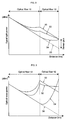
- FIG. 4 is a schematic diagram showing distance variation of SNR calculated from the results shown in FIGS. 2 and 3.
- the vertical axis expresses SNR (dB) and the horizontal axis expresses distance (km) .
- a characteristic curve 40 shows a case in which an optical fiber having a zero Raman gain coefficient is used as the optical fiber 12.
- a characteristic curve 42 shows a case in which an optical fiber having a Raman gain coefficient of small value other than zero is used as the optical fiber 12.
- a characteristic curve 44 shows a case of conventional system.
- a broken line 46 shows distance variation of the SNR when the Raman amplification is not used. When the Raman amplification is not used, the SNR is constant because both optical signal and optical noise attenuate according to the loss of the optical fiber.
- the Raman amplification occurs and optical noise is also generated in the optical fiber 10 as shown with the characteristic curves 20 and 30. Accordingly, as shown with the characteristic curve 40, the SNR deteriorates at that part. However, since the Raman amplification does not occur in the optical fiber 12, the SNR is constant in the optical fiber 12.
- the Raman amplification occurs and also optical noise is generated in the latter half part of the optical fiber 10 as shown with the characteristic curves 22 and 32. Accordingly, the SNR first deteriorates in the latter half part of the optical fiber 10 and further deteriorates in the optical fiber 12 as shown with the characteristic curve 42. Consequently, the SNR at the output end of the optical fiber 12 generally becomes smaller as compared with the case using the optical fiber of the zero Raman gain coefficient.
- the large Raman gain occurs and also optical noise is generated at the part near to the optical signal emission end of the optical fiber 12 as shown with the characteristic curves 24 and 34. Accordingly, the SNR rapidly deteriorates as approaching to the optical signal emission end of the optical fiber 12 as shown with the characteristic curve 44. The SNR at the output end of the optical fiber 12 becomes the smallest in the above cases.
- the improving effect of the SNR depends on how far the Raman amplification can be shifted toward the optical signal input side.
- the Raman gain (dB) increases proportional to the intensity (mW or W) of the pumping light, and the Raman gain and the optical noise power caused by the Raman gain are proportional.
- the optical noise amount generated by the same Raman gain is unchanged.
- Optical noises generated near to the receiver are detected as the optical noises of almost the same level.
- the part of the Raman gain occurrence shifts to the transmitter side the optical noise detected at the receiver is reduced according to the shifted length toward the transmitter side. Therefore, the more the location of the Raman gain occurrence shifts to the transmitter side, the more the SNR at the receiver is improved.
- the Raman gain coefficient is inversely proportional to the effective core area, and so it was checked how the SNR is improved in relation to the ratio of the effective core areas of the optical fibers 10 and 12 and the length of the optical fiber 12.
- FIGS. 5 and 6 show the measured result.
- the horizontal axes express the ratio A eff2 / A eff1 between the effective core area A eff2 of the optical fiber 12 to the effective core area A eff1 of the optical fiber 10, and the horizontal axes express the relative value ⁇ SNR (dB) of the SNR.
- FIG. 6 is an enlarged diagram showing the part where the effective core area ratio is 1.5 or less.
- the pumping power is 500 mW.
- the Raman gain coefficient depends on a dopant and its density besides the effective core area.
- the dopant includes GeO 2 , P 2 O 5 , and B 2 O 3 etc.
- the SNRs of the optical fibers 12 of 10 km, 20 km and 30 km in length were checked, and the examination proved that the SNR was improved at each length when the effective core area of the optical fiber 12 is larger than that of the optical fiber 10 by 8 %, preferably 10 %.
- a characteristic curve 50 shows a case that the optical fiber 12 is 10 km
- a characteristic curve 52 shows a case that the optical fiber is 20 km
- a characteristic curve 54 shows a case that the optical fiber is 30 km. Accordingly, in terms of the Raman gain coefficient, the SNR is improved when the ratio of the Raman gain coefficient of the optical fiber 12 to that of the optical fiber 10 is 1/1.08 or less, preferably 1/1.1 or less.
- This embodiment is applicable to an optical repeater transmission line composed of three types of fibers in a repeater span.
- a single mode fiber (SMF) of a 110 ⁇ m 2 effective core area, +19 ps/nm/km chromatic dispersion, and 15 km in length a reverse dispersion fiber (RDF) of 35 ⁇ m 2 effective core area, -20 ps/nm/km chromatic dispersion, and 20 km in length
- RDF reverse dispersion fiber
- DSF dispersion shift fiber
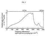
- the Raman amplification has the highest pumping efficiency when the laser light having a wavelength shorter than that of the optical signal by an inherent wavelength of the medium to cause the Raman amplification is used as the pumping light source. This wavelength difference is called Raman shift wavelength.
- FIG. 7 shows a characteristic diagram of Raman gain relative to SiO 2 .
- the horizontal axis expresses a frequency difference between the optical signal and the pumping light, and the vertical axis expresses a relative gain core area.
- 1 cm -1 is equal to 30 GHz.
- the laser light source of the single wavelength is used as the pumping light source for the Raman amplification, it is also applicable to introduce the light obtained by multiplexing the output lights from a plurality of laser sources of different wavelengths into the optical fiber 12 from the back.
- the wavelength difference of each laser light source is equal to the Raman shift wavelength. Since the laser light of each wavelength is sequentially amplified in the optical fibers 10 and 12, ultimately the point where the optical signal is amplified can be shifted to the input side of the optical signal.
- the Raman shift wavelength is equal to a frequency of 13 THz.
- a 1450 nm pumping wavelength is to amplify 1550 nm
- a 1360 nm pumping wavelength is to amplify 1450 nm.
- the 1360 nm laser light source 60a, the 1450 nm laser light source 60b, and a combiner 62 to combine output lights from the both laser light sources are disposed instead of the laser diode 16.
- Elements identical to those in Fig. 1 are labeled with common reference numerals. In this configuration, the 1360 nm laser light and the 1450 nm laser light together enter the optical fiber 12 from the back.
- the 1450 nm laser light is amplified by the 1360 nm laser light while propagating on the optical fibers 10 and 12 in the opposite direction to that of the optical signal.
- the 1450 nm amplified laser light amplifies the optical signal propagating on the optical fibers 10 and 12.
- the Raman amplification requires a certain propagation distance. Accordingly, the range in which the optical signal is amplified can be shifted toward the input side of the optical signal using this kind of the multi-step type Raman amplification, and also the SNR can be improved because of the reasons priorly explained.
- the output lights from the laser light sources 60a and 60b can be introduced by discrete optical coupler separately into the optical fiber 12.
- a fiber Raman amplifier having an improved SNR can be realized.
Landscapes
- Physics & Mathematics (AREA)
- Electromagnetism (AREA)
- Engineering & Computer Science (AREA)
- Plasma & Fusion (AREA)
- Optics & Photonics (AREA)
- Optical Modulation, Optical Deflection, Nonlinear Optics, Optical Demodulation, Optical Logic Elements (AREA)
- Lasers (AREA)
Applications Claiming Priority (2)
| Application Number | Priority Date | Filing Date | Title |
|---|---|---|---|
| JP2000194646A JP2002014383A (ja) | 2000-06-28 | 2000-06-28 | ラマン増幅器 |
| JP2000194646 | 2000-06-28 |
Publications (3)
| Publication Number | Publication Date |
|---|---|
| EP1168530A2 true EP1168530A2 (fr) | 2002-01-02 |
| EP1168530A3 EP1168530A3 (fr) | 2002-09-11 |
| EP1168530B1 EP1168530B1 (fr) | 2004-12-22 |
Family
ID=18693437
Family Applications (1)
| Application Number | Title | Priority Date | Filing Date |
|---|---|---|---|
| EP01115122A Expired - Lifetime EP1168530B1 (fr) | 2000-06-28 | 2001-06-21 | Amplificateur Raman |
Country Status (5)
| Country | Link |
|---|---|
| US (1) | US6519078B2 (fr) |
| EP (1) | EP1168530B1 (fr) |
| JP (1) | JP2002014383A (fr) |
| CA (1) | CA2350021A1 (fr) |
| DE (1) | DE60107907T2 (fr) |
Cited By (2)
| Publication number | Priority date | Publication date | Assignee | Title |
|---|---|---|---|---|
| DE10112806C1 (de) * | 2001-03-16 | 2002-10-10 | Siemens Ag | Pumpquelle mit erhöhter Pumpleistung zur optischen breitbandigen Raman-Verstärkung |
| US7012742B2 (en) * | 2003-06-11 | 2006-03-14 | Samsung Electronics Co., Ltd. | Gain-clamped semiconductor optical amplifier using Raman amplification principle |
Families Citing this family (25)
| Publication number | Priority date | Publication date | Assignee | Title |
|---|---|---|---|---|
| US6760148B2 (en) | 1998-03-24 | 2004-07-06 | Xtera Communications, Inc. | Nonlinear polarization amplifiers in nonzero dispersion shifted fiber |
| US6693737B2 (en) | 1998-03-24 | 2004-02-17 | Xtera Communications, Inc. | Dispersion compensating nonlinear polarization amplifiers |
| US6600592B2 (en) | 1998-03-24 | 2003-07-29 | Xtera Communications, Inc. | S+ band nonlinear polarization amplifiers |
| US6356384B1 (en) * | 1998-03-24 | 2002-03-12 | Xtera Communications Inc. | Broadband amplifier and communication system |
| US6597493B2 (en) | 2000-05-05 | 2003-07-22 | The Regents Of The University Of Michigan | Nonlinear fiber amplifiers used for a 1430-1530nm low-loss window in optical fibers |
| US6359725B1 (en) | 1998-06-16 | 2002-03-19 | Xtera Communications, Inc. | Multi-stage optical amplifier and broadband communication system |
| US6335820B1 (en) | 1999-12-23 | 2002-01-01 | Xtera Communications, Inc. | Multi-stage optical amplifier and broadband communication system |
| CA2335289C (fr) | 1998-06-16 | 2009-10-13 | Mohammed Nazrul Islam | Element optique de compensation et d'amplification de dispersion, methode de reduction de l'angle d'inclinaison du gain et appareil permettant de minimiser l'interaction non lineaire entre pompes de bande |
| US6885498B2 (en) | 1998-06-16 | 2005-04-26 | Xtera Communications, Inc. | Multi-stage optical amplifier and broadband communication system |
| CA2365109A1 (fr) | 1999-12-24 | 2001-07-05 | Sumitomo Electric Industries, Ltd. | Ligne a transmission optique, procede de fabrication de ligne a transmission optique et systeme de transmission optique |
| JP2001223420A (ja) * | 2000-02-10 | 2001-08-17 | Sumitomo Electric Ind Ltd | ラマン増幅器、光伝送システムおよび光ファイバ |
| JP3558124B2 (ja) * | 2000-07-25 | 2004-08-25 | 住友電気工業株式会社 | ラマン増幅器及びそれを用いた光伝送システム |
| JP2002062552A (ja) * | 2000-08-18 | 2002-02-28 | Sumitomo Electric Ind Ltd | ラマン増幅器および光通信システム |
| CA2340848A1 (fr) * | 2001-03-15 | 2002-09-15 | John D. Mcnicol | Gestion de dispersion pour reseaux optiques a haute vitesse de grande portee |
| US6532101B2 (en) | 2001-03-16 | 2003-03-11 | Xtera Communications, Inc. | System and method for wide band Raman amplification |
| US6810214B2 (en) | 2001-03-16 | 2004-10-26 | Xtera Communications, Inc. | Method and system for reducing degradation of optical signal to noise ratio |
| US6587259B2 (en) | 2001-07-27 | 2003-07-01 | Xtera Communications, Inc. | System and method for controlling noise figure |
| JP3866592B2 (ja) * | 2002-03-12 | 2007-01-10 | 富士通株式会社 | ラマン増幅を用いた光伝送システム |
| US6778321B1 (en) | 2002-03-15 | 2004-08-17 | Xtera Communications, Inc. | Fiber optic transmission system for a metropolitan area network |
| US7197245B1 (en) | 2002-03-15 | 2007-03-27 | Xtera Communications, Inc. | System and method for managing system margin |
| US6819478B1 (en) | 2002-03-15 | 2004-11-16 | Xtera Communications, Inc. | Fiber optic transmission system with low cost transmitter compensation |
| US20050078714A1 (en) * | 2003-10-08 | 2005-04-14 | Hiroshi Komine | High power fiber laser with eye safe wavelengths |
| EP1531563B1 (fr) * | 2003-11-14 | 2009-04-08 | Alcatel Lucent | Amplificateur Raman à ordres multiples |
| US7894128B2 (en) * | 2007-02-01 | 2011-02-22 | Bae Systems Information And Electronic Systems Integration Inc. | Real-time terahertz imaging system for the detection of concealed objects |
| US7869673B2 (en) * | 2008-08-29 | 2011-01-11 | Xtera Communications, Inc. | Remote larger effective area optical fiber |
Family Cites Families (11)
| Publication number | Priority date | Publication date | Assignee | Title |
|---|---|---|---|---|
| US5058974A (en) | 1989-10-06 | 1991-10-22 | At&T Bell Laboratories | Distributed amplification for lightwave transmission system |
| US5039199A (en) * | 1989-12-29 | 1991-08-13 | At&T Bell Laboratories | Lightwave transmission system having remotely pumped quasi-distributed amplifying fibers |
| US6191877B1 (en) * | 1995-02-17 | 2001-02-20 | Lucent Technologies Inc. | WDM optical fiber system using Raman amplification |
| US5623508A (en) | 1996-02-12 | 1997-04-22 | Lucent Technologies Inc. | Article comprising a counter-pumped optical fiber raman amplifier |
| CA2195614C (fr) * | 1996-02-16 | 2005-06-28 | George F. Wildeman | Cable optique symetrique a gestion de dispersion et systeme associe |
| US5959750A (en) * | 1996-06-06 | 1999-09-28 | Lucent Technologies Inc. | Method of upgrading transmission capacity by Raman amplification |
| US6081366A (en) * | 1997-08-28 | 2000-06-27 | Lucent Technologies Inc. | Optical fiber communication system with a distributed Raman amplifier and a remotely pumped er-doped fiber amplifier |
| US6101024A (en) | 1998-03-24 | 2000-08-08 | Xtera Communications, Inc. | Nonlinear fiber amplifiers used for a 1430-1530nm low-loss window in optical fibers |
| US6163636A (en) * | 1999-01-19 | 2000-12-19 | Lucent Technologies Inc. | Optical communication system using multiple-order Raman amplifiers |
| US6147794A (en) * | 1999-02-04 | 2000-11-14 | Lucent Technologies, Inc. | Raman amplifier with pump source for improved performance |
| JP2000349716A (ja) * | 1999-06-04 | 2000-12-15 | Nippon Telegr & Teleph Corp <Ntt> | 光伝送システム |
-
2000
- 2000-06-28 JP JP2000194646A patent/JP2002014383A/ja not_active Withdrawn
-
2001
- 2001-06-11 CA CA002350021A patent/CA2350021A1/fr not_active Abandoned
- 2001-06-21 US US09/887,915 patent/US6519078B2/en not_active Expired - Fee Related
- 2001-06-21 DE DE60107907T patent/DE60107907T2/de not_active Expired - Fee Related
- 2001-06-21 EP EP01115122A patent/EP1168530B1/fr not_active Expired - Lifetime
Cited By (3)
| Publication number | Priority date | Publication date | Assignee | Title |
|---|---|---|---|---|
| DE10112806C1 (de) * | 2001-03-16 | 2002-10-10 | Siemens Ag | Pumpquelle mit erhöhter Pumpleistung zur optischen breitbandigen Raman-Verstärkung |
| US6707598B2 (en) | 2001-03-16 | 2004-03-16 | Siemens Aktiengesellschaft | Pump source with increased pump power for optical broadband Raman amplification |
| US7012742B2 (en) * | 2003-06-11 | 2006-03-14 | Samsung Electronics Co., Ltd. | Gain-clamped semiconductor optical amplifier using Raman amplification principle |
Also Published As
| Publication number | Publication date |
|---|---|
| EP1168530B1 (fr) | 2004-12-22 |
| US20020001123A1 (en) | 2002-01-03 |
| JP2002014383A (ja) | 2002-01-18 |
| CA2350021A1 (fr) | 2001-12-28 |
| EP1168530A3 (fr) | 2002-09-11 |
| DE60107907D1 (de) | 2005-01-27 |
| DE60107907T2 (de) | 2005-12-15 |
| US6519078B2 (en) | 2003-02-11 |
Similar Documents
| Publication | Publication Date | Title |
|---|---|---|
| EP1168530B1 (fr) | Amplificateur Raman | |
| US6178038B1 (en) | Optical amplifier having an improved noise figure | |
| US6263139B1 (en) | Optical transmission system with group velocity dispersion compensation | |
| CN1222124C (zh) | 用于在光纤通信系统中生长分布式喇曼放大的级联泵浦系统和方法 | |
| US6542290B1 (en) | Optical amplifier | |
| EP0971493A2 (fr) | Compensation de la dispersion chromatique et des non-linearités à la communication à fibres optiques | |
| US6748178B2 (en) | Optical transmission line | |
| US6529315B2 (en) | Optical amplifier providing dispersion compensation | |
| US7248399B2 (en) | Optical fiber for Raman amplification, optical fiber coil, Raman amplifier, and optical communication system | |
| US7034991B2 (en) | Optical amplification and transmission system | |
| US6823107B2 (en) | Method and device for optical amplification | |
| US6483633B2 (en) | Raman amplifier | |
| US7038842B2 (en) | Reduced four-wave mixing and Raman amplification architecture | |
| JP2003526819A (ja) | ラマン増幅器装置 | |
| WO2019198171A1 (fr) | Amplificateur optique, système de communication optique et procédé d'amplification optique | |
| US7177073B2 (en) | Multiple order Raman amplifier | |
| US20030234973A1 (en) | Method and device for optical fiber transmission using raman amplification | |
| JP3626660B2 (ja) | 無中継光伝送システムおよび無中継光伝送方法 | |
| JP4172315B2 (ja) | 光伝送路及び光伝送システム | |
| JP3871892B2 (ja) | 四波混合効果が削減されたラマン増幅光システム | |
| EP1289078A2 (fr) | Ligne de transmission optique et système de communication optique | |
| US7046431B1 (en) | Light amplifier and light amplifying method | |
| JP2002299738A (ja) | 光伝送システム | |
| JPH1117624A (ja) | 光伝送路 | |
| JP2008153558A (ja) | 光伝送システム及びその信号スペクトラム補正方法 |
Legal Events
| Date | Code | Title | Description |
|---|---|---|---|
| PUAI | Public reference made under article 153(3) epc to a published international application that has entered the european phase |
Free format text: ORIGINAL CODE: 0009012 |
|
| AK | Designated contracting states |
Kind code of ref document: A2 Designated state(s): AT BE CH CY DE DK ES FI FR GB GR IE IT LI LU MC NL PT SE TR |
|
| AX | Request for extension of the european patent |
Free format text: AL;LT;LV;MK;RO;SI |
|
| PUAL | Search report despatched |
Free format text: ORIGINAL CODE: 0009013 |
|
| AK | Designated contracting states |
Kind code of ref document: A3 Designated state(s): AT BE CH CY DE DK ES FI FR GB GR IE IT LI LU MC NL PT SE TR |
|
| AX | Request for extension of the european patent |
Free format text: AL;LT;LV;MK;RO;SI |
|
| RIC1 | Information provided on ipc code assigned before grant |
Free format text: 7H 01S 3/30 A |
|
| 17P | Request for examination filed |
Effective date: 20020809 |
|
| AKX | Designation fees paid |
Designated state(s): DE FR GB |
|
| GRAP | Despatch of communication of intention to grant a patent |
Free format text: ORIGINAL CODE: EPIDOSNIGR1 |
|
| GRAS | Grant fee paid |
Free format text: ORIGINAL CODE: EPIDOSNIGR3 |
|
| GRAA | (expected) grant |
Free format text: ORIGINAL CODE: 0009210 |
|
| AK | Designated contracting states |
Kind code of ref document: B1 Designated state(s): DE FR GB |
|
| REG | Reference to a national code |
Ref country code: GB Ref legal event code: FG4D |
|
| REG | Reference to a national code |
Ref country code: IE Ref legal event code: FG4D |
|
| REF | Corresponds to: |
Ref document number: 60107907 Country of ref document: DE Date of ref document: 20050127 Kind code of ref document: P |
|
| PG25 | Lapsed in a contracting state [announced via postgrant information from national office to epo] |
Ref country code: GB Free format text: LAPSE BECAUSE OF NON-PAYMENT OF DUE FEES Effective date: 20050621 |
|
| PLBE | No opposition filed within time limit |
Free format text: ORIGINAL CODE: 0009261 |
|
| STAA | Information on the status of an ep patent application or granted ep patent |
Free format text: STATUS: NO OPPOSITION FILED WITHIN TIME LIMIT |
|
| ET | Fr: translation filed | ||
| 26N | No opposition filed |
Effective date: 20050923 |
|
| PG25 | Lapsed in a contracting state [announced via postgrant information from national office to epo] |
Ref country code: DE Free format text: LAPSE BECAUSE OF NON-PAYMENT OF DUE FEES Effective date: 20060103 |
|
| GBPC | Gb: european patent ceased through non-payment of renewal fee |
Effective date: 20050621 |
|
| PG25 | Lapsed in a contracting state [announced via postgrant information from national office to epo] |
Ref country code: FR Free format text: LAPSE BECAUSE OF NON-PAYMENT OF DUE FEES Effective date: 20050630 |
|
| REG | Reference to a national code |
Ref country code: FR Ref legal event code: ST Effective date: 20111125 |