EP1168669A2 - Système de communication à commutation de paquets auto-adressés avec saut de pinceaux d'antenne et mémoire partagée à ports multiples - Google Patents
Système de communication à commutation de paquets auto-adressés avec saut de pinceaux d'antenne et mémoire partagée à ports multiples Download PDFInfo
- Publication number
- EP1168669A2 EP1168669A2 EP01113509A EP01113509A EP1168669A2 EP 1168669 A2 EP1168669 A2 EP 1168669A2 EP 01113509 A EP01113509 A EP 01113509A EP 01113509 A EP01113509 A EP 01113509A EP 1168669 A2 EP1168669 A2 EP 1168669A2
- Authority
- EP
- European Patent Office
- Prior art keywords
- queue
- router
- uplink data
- downlink
- cell
- Prior art date
- Legal status (The legal status is an assumption and is not a legal conclusion. Google has not performed a legal analysis and makes no representation as to the accuracy of the status listed.)
- Withdrawn
Links
Images


Classifications
-
- H—ELECTRICITY
- H04—ELECTRIC COMMUNICATION TECHNIQUE
- H04B—TRANSMISSION
- H04B7/00—Radio transmission systems, i.e. using radiation field
- H04B7/14—Relay systems
- H04B7/15—Active relay systems
- H04B7/185—Space-based or airborne stations; Stations for satellite systems
- H04B7/1851—Systems using a satellite or space-based relay
- H04B7/18515—Transmission equipment in satellites or space-based relays
-
- H—ELECTRICITY
- H04—ELECTRIC COMMUNICATION TECHNIQUE
- H04B—TRANSMISSION
- H04B7/00—Radio transmission systems, i.e. using radiation field
- H04B7/14—Relay systems
- H04B7/15—Active relay systems
- H04B7/185—Space-based or airborne stations; Stations for satellite systems
- H04B7/18578—Satellite systems for providing broadband data service to individual earth stations
- H04B7/18589—Arrangements for controlling an end to end session, i.e. for initialising, synchronising or terminating an end to end link
-
- H—ELECTRICITY
- H04—ELECTRIC COMMUNICATION TECHNIQUE
- H04B—TRANSMISSION
- H04B7/00—Radio transmission systems, i.e. using radiation field
- H04B7/14—Relay systems
- H04B7/15—Active relay systems
- H04B7/204—Multiple access
- H04B7/2041—Spot beam multiple access
Definitions
- the present invention relates to satellite communication systems.
- the present invention relates to a satellite communication system including a self addressed packet switch that stores data downlink hop location queues in a multiport shared memory and that hops a downlink beam between terrestrial cells.
- Satellites have long been used to provide communication capabilities on a global scale.
- a satellite includes multiple uplink and downlink antennas, each of which provides communication bandwidth to a large service region using multiple spot beams.
- the area covered by a spot beam is commonly referred to as a cell, and color coded spot beams are assigned in a pattern called a laydown to cover the service region.
- Each spot beam provides limited bandwidth. Yet, as a satellite provides additional simultaneous spot beams, the cost, complexity, and power requirements of the satellite increase. Thus, the ability to provide service to a laydown with a large number of cells was limited by prior satellite and antenna design and cost considerations.
- a preferred embodiment of the present invention provides a router for a communication satellite.
- the router includes a multiport shared memory with storage for at least two downlink hop location queues, a packet switch that routes self addressed uplink data from an input port to an output port coupled to the multiport shared memory, and a routing table (e.g., in an inbound module) coupled to the packet switch.
- the routing table stores queue tags that identify at least one of the downlink hop location queues in which the uplink data should be stored. In addition, the routing table stores routing tags the direct the packet switch to route the uplink data from one of its input ports to one or more of its output ports. The routing table may also store replacement address information for the uplink data (e.g., replacement VPI / VCI addresses for ATM cells indicative of the next hop, or destination).
- replacement address information for the uplink data e.g., replacement VPI / VCI addresses for ATM cells indicative of the next hop, or destination.
- the downlink hop location queues may be distinguished by priority, code rate, and hop location.
- the downlink hop location queues may be fixed in size, dynamically sized (by allocating or deallocating memory from the shared memory), or a combination of the two.
- any of the downlink hop location queues may be characterized by a minimum guaranteed size, a maximum size, and/or a data priority threshold (that determines when low priority data is rejected).
- a dedicated controller queue may be provided in the shared memory (e.g., the hop location 15, light code rate, priority 15 queue).
- the bandwidth switch 100 includes a controller 102 and a waveform processing chain that operates on data provided by the data source 104.
- the waveform processing chain includes a waveform generator 106, an amplifier 108, and a feed switch 110.
- the waveform processing chain further includes a first feed path 112 and a second feed path 114 that may be characterized by a polarization effect on the waveform that propagates along the feed paths 112-114.
- the polarization effect may induce, for example, clockwise (right) or counter clockwise (left) polarization in the waveform.
- the first feed path 112 terminates in a first radiating element 116 (e.g., a feed horn).
- the second feed path terminates in a second radiating element 118 (e.g., another feed horn).
- the first and second feed horns 116, 118 illuminate the subreflector 120.
- the subreflector 120 illuminates the main reflector 122 that projects downlink beams onto terrestrial cells.
- the first and second feed horns 116, 118, the subreflector 120, and the main reflector 122 form a Multiple Beam Array Antenna (MBA) to direct spot beam coverage to distinct terrestrial cells.
- MSA Multiple Beam Array Antenna
- Additional feed horns may be used with the MBA to generate additional spot beams, and multiple independent MBAs may be provided.
- the waveform generator 106 accepts baseband data from the data source 104 and creates a waveform to be transmitted (after amplification by the amplifier 108).
- the switch 110 selects the particular feed path 112-114 along which the waveform propagates (and thus, in certain embodiments, the polarization and/or hop location associated with the waveform).
- the controller 102 exercises color control over the waveform to be transmitted.
- the controller 102 may output one or more control signals (collectively referred to as a color selection signal) that determine, for example, the frequency, polarization, or hop location of the waveform to be transmitted.
- the beam color components include Even and Odd hop locations, Left and Right polarization, and first and second frequencies. Eight different colors are therefore available: 1EL, 1ER, 10L, 10R, 2EL, 2ER, 20L, 20R.
- the bandwidth switch 200 includes a data scheduler 202, a data router 204, and a waveform processing chain including a QPSK modulator 206, an upconverter 208, and a traveling wave tube amplifier (TWTA) 210.
- the switch 110 is illustrated in Figure 2 as a ferrite switch 110 that directs the waveform to be transmitted through either the first feed path 112 or the second feed path 114.
- additional ferrite switches 212 and 214 in the feed paths 112-114 provide additional signal isolation (e.g., approximately 20db between input and output when the ferrite switch is off).
- the additional ferrite switches 212-214 operate under control of the color selection output to pass or block a waveform to be transmitted through the feed paths 112-114.
- the ferrite switch 214 is coupled through the load 228 to ground.
- the ferrite switch 212 is coupled through the load 226 to ground.
- Figure 2 shows a color selection output 216, two frequency selection inputs 218 and 220, a feed path selection input 222, and an intermediate waveform output 224.
- the bandwidth switch 200 accepts baseband data from the router 204 (e.g., an ATM cell router), and creates a waveform to be transmitted using the waveform processing chain.
- the waveform processing starts by directly converting baseband I and Q data to an intermediate frequency of, for example, 750 MHz.
- the waveform processing selects one of F1 (e.g., 3.175 MHz) and F2 (e.g., 3.425) and one of F3 (e.g., 16 GHz) and F4 (e.g., 17.4 GHz) to produce a waveform to be transmitted with a final center frequency at one of 18.425 GHz, 18.675 GHz, 19.825 GHz, and 20.075 GHz.
- the scheduler 204 monitors the propagation of data through the waveform processing chain and determines the color of the waveform to be transmitted. To that end, the scheduler 204 provides the color selection output 216 that indicates, as examples, the frequency, polarization, and hop location for the waveform to be transmitted.
- the TWTA 210 amplifies the waveform to be transmitted, while the switch 110 determines along which feed path 112-114 (or additional feed paths) the amplified waveform will propagate.
- the switch 110 includes the feed path selection input 222 responsive to information on the color selection output 216 (e.g., a hop selection signal). Because the feed paths 112-114 are generally (though not necessarily) associated with feed horns that produce spot beams in different hop locations, the hop selection signal acts to determine the hop location of the waveform to be transmitted.
- the hop locations below are designated Even or Odd, but are not restricted to even or odd frames. Instead Even and Odd generally designate mutually exclusive time periods.
- either of the feed paths 112-114 may be characterized by a polarization effect on the waveform that propagates along the feed path.
- the color selection output 216 may also determine the polarization color component of the waveform to be transmitted.
- separate feed paths may be provided for any number of desired combinations of polarization and hop location.
- the transmitted waveform manifests itself as a beam spot that, typically, provides downlink bandwidth for a terrestrial cell.
- the bandwidth switch 200 may operate onboard a first satellite that supports a cellular coverage area using a set of spot beams.
- the scheduler 202 ensures that the waveforms to be transmitted have the appropriate beam colors to minimize co-channel, adjacent channel, and cross polarization for the cellular coverage area and the eight possible beam colors.
- the bandwidth switch 200 allows the first satellite to modify its beam colors to accommodate the second satellite.
- the bandwidth switch 200 allows the first and second assignment of spot beams to the coverage area to coexist in a minimally interfering manner.
- the resultant beam laydown may then be minimally interfering initially for a single satellite, and later reconfigured to be minimally interfering with regard to a particular type of interference or interferences for additional satellites providing bandwidth for the same coverage area.
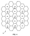
- FIG. 3 that figure illustrates a beam laydown 300 that uses hopping beams.
- the coverage area is generally divided into cells as shown in idealized form, for example, by the hexagonal cells 302 and 304.
- Each of the cells is also labeled with a beam color.
- a beam of color 1OL provides bandwidth for the cell 302
- a beam of color 2EL provides bandwidth for the cell 304.
- the laydown 300 is characterized in that, for mutually exclusive hop locations, a only six cochannel interferers (CCI) (caused by a beam of the same color), zero adjacent channel interferers (ACI) (caused by a beam differing in only one color component), and zero cross polarization interferers (XPI) (caused by a beam differing only in polarization) exist for any given cell.
- CCI cochannel interferers
- ACI zero adjacent channel interferers
- XPI zero cross polarization interferers
- cell 320 does not provide CCI because it has an odd color component and is not provided with spot beam energy at the same time as the cell 306 (color 1ER) (i.e., the hop locations are mutually exclusive).
- the laydown 300 also provides minimal interference when hop locations are non-mutually exclusive.
- the ACIs are cells 322 and 324, while the XPIs are cells 320 and 326. Note that not all colors (e.g., 20L) need be used in a beam hopping beam laydown.
- Figure 4 shows the laydown 300 as well. In Figure 4, however, only the even hop locations are marked. Similarly, Figure 5 shows the beam laydown 300 with only the odd hop locations marked.
- the router 600 includes thirty-five inbound modules (IBMs), three of which are designated 602, 604, 606.
- the IBMs 602-606 are coupled to input ports of an ATM cell switch 608.
- the ATM cell switch 608 has thirty-three outputs coupled to individual outbound modules (OBMs), three of which are designated 610, 612, 614. Paris of uplink demodulators feed each IBM 602-606, while the OBMs 610-614 feed downlink modulators.
- IBMs inbound modules
- OBMs outbound modules
- the router 600 provides a self addressed packet switching function.
- the router 600 uses addressing or destination information present in uplink data (e.g., ATM cells) to deliver the cells to a specific data queue that feeds a downlink beam appropriate for the destination or next hop of the cell.
- uplink data e.g., ATM cells
- the VPI / VCI fields in an ATM cell may be used to guide the cell into an appropriate downlink queue. Cells may first be discarded however, if they fail their header error check.
- the output of the IBMs 602-606 includes a routing tag, a queue tag, and the (possibly modified) cell itself.
- the role of the IBMs 602-606, the routing tag and, the queue tag will be described in more detail below with respect to Figure 7.
- the ATM cell switch 608 uses the bits in the routing tag to connect a cell switch input port to a cell switch output port.
- the queue tag, a portion of the routing tag, and the cell itself then flow through the switch to the OBM connected to the selected output port.
- each OBM 610-614 includes a set of downlink queues that feed downlink beams directed to predetermined terrestrial cells.
- the queue tag determines in which downlink queue the cell will be inserted in the OBM (and may be indicative of cell priority and downlink coding rate).
- the IBMs 602-606, the ATM cell switch 608, and the OBMs 610-614 operate in concert to deliver cells to an appropriate downlink queue in a self addressed manner.
- Figure 7 illustrates an implementation 700 of the IBMs 602-606.
- the implementation 700 includes a routing or lookup table 702 and an output buffer 704.
- An incoming ATM cell generally indicated at 706 is shown to include (among other fields) a payload 708 and a VPI/VCI address 710.
- Figure 7 also illustrates a particular routing tag 712, queue tag 714, and optional replacement VPI/VCI 716 field for the cell from among those stored in the routing table 702. If the cell is modified (e.g., by changing its VPI/VCI), the IBM will also recompute the cell header error check.
- a ground based Network Control Center (NCC) may dynamically update the routing table 702 to ensure proper routing of cells from the current network node (e.g., the satellite) to the next network node (e.g., a ground terminal).
- NCC Network Control Center
- the VPI/VCI 710 of the cell 706 addresses the routing table 702.
- the routing table 702 provides the routing tag 712, queue tag 714, and new VPI/VCI addresses 716 (e.g., for the next hop that the cell will make).
- a NULL entry in the routing table 702 may indicate that the cell is to be discarded. Any modifications to the uplink cell result in the IBM recomputing an error check for the uplink cell as well.
- This information enters the output buffer 704 (which may be, for example, 8191 cells in length). Once in the output buffer 704, the information awaits selection by an arbitration algorithm before it enters the cell switch 608.
- the arbitration algorithm may give preference to the oldest cells (e.g., using a two bit quantization of clock cycle cell age), the remaining capacity of the output buffer 704 (e.g., using a three bit quantization of total input queue size), and the like.
- the routing tag 712 is preferably seven bits in length.
- the ATM cell switch 608 uses six of the seven bits internally to connect an input port to an output port determined by the six bits. For future expandability, the seventh bit may be used, for example, to support larger switches with additional output ports.
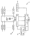
- the OBM 800 includes an OBM controller 802 coupled to an external cell memory 804.
- the OBM controller 802 integrates, preferably, into a single ASIC logic that implements a switch interface controller (SIC) 806 and a switch interface data handler (SID) 808.
- the SIC 806 couples to a downlink schedule table 810, a queue statistics memory 812, a linked list memory 814, and a pointer memory 816.
- the OBM 800 includes a first Reed-Solomon encoder (RSE) 818, a second RSE 820, interface electronics (IEA) 822 coupled to interleaving memory 824, and a downlink frame formatter (DLF) 826.
- RSE Reed-Solomon encoder
- IEEEA interface electronics
- the external cell memory 804 is preferably organized into numerous queues.
- the queues may be distinguished by characteristics such as hop location, priority, and code rate, or other criteria. In general, for each hop location, there may be one or more code rates, each having one or more priority queues.
- there are 16 downlink hop locations (referred to as a subclass) the external cell memory 804 includes 16 light coding queues and 16 heavy coding queues (i.e., 512 total queues). Each of the 16 light and 16 heavy coding queues represents a predetermined priority.
- One queue (e.g., priority 15, subclass 15, light coding) may be reserved for system controller traffic.
- the queue tag determines the subclass and the queue for which a cell is destined.
- the external cell memory 804 is preferably a multiport memory shared between output ports of the cell switch 608.
- the multiport nature of the external cell memory 804 resides in its role as shared storage for multiple hop locations (i.e., Beam A and Beam B that share a single physical cell switch 608 output port) served by the single OBM controller 802.
- the memory provided by the external cell memory 804 may be allocated in a fixed or dynamic manner in several different ways. As one example, one or more queues may be allocated a fixed amount of memory to meet the expected long term needs of the subclass and priority associated with the queue. The remaining memory may then be shared by the remaining queues. To guarantee a minimum bandwidth for each queue, a minimum threshold amount of memory may be reserved for each queue. Thus, the external cell memory 804 permits pairing destination bandwidth needs for a particular destination at a particular time with allocations of queue memory. To that end, the NCC may dynamically uplink to the satellite changes to the manner in which memory is allocated. The thresholds, maximum queue size, minimum queue size, and the like are stored in the pointer memory 816.
- the SIC 806 comprises logic that directs the activities of the OBM controller 802, including obtaining cells from the cell switch 608 through the SID 808. As will be described in more detail below, the SIC 806 makes a determination regarding whether the cell should be accepted or rejected using parameters for each queue stored in the pointer memory 816. If a cell is accepted, the SID 808 stores the cell in a queue in the external cell memory 804. The SIC 806 then updates the linked list memory 814 to record where the cell was stored in the external cell memory 804.
- the SIC 806 also updates the queue statistics memory 812 to reflect the number of cells in each queue in the external memory 804, the number of cells accepted or rejected for each queue, peak queue occupancies, the number of cells pulled from the each queue for transmission, and the number of threshold failure cells.
- the SIC 806 and SID 808 handle retrieval of cells from the external cell memory 804 under in accordance with a schedule stored in the downlink schedule table 810.
- the downlink schedule table specifies for each frame parameters such as code selection, power gating, cell selection, and the like.
- the RSEs 818 and 820 apply a Reed-Solomon block code (e.g., a (236, 212) block code) to cells retrieved for transmission.
- the IEA 822 subsequently interleaves, scrambles, and convolutionally codes the block coded cells.
- the convolutional code may be a 3/4 rate constraint length 7 punctured convolutional code for light coded cells, and a 3/8 rate constraint length 7 punctured convolutional code for heavy coded cells.
- the DLF 826 then forms, preferably, a two payload downlink frame for the downlink, including overhead information (e.g., synchronization codes, code identifiers, guard time, and the like). Each payload may independently carry 12 heavy coded cells or 24 light coded cells.
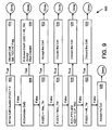
- a flow diagram 900 presents a series of determinations made by the SIC 806 when queue are fixed in size.
- the SIC 806 determines whether there is any free memory in which to store the cell. If the free cell counter (FCC) is zero, the cell is discarded (step 904). Otherwise the SIC 806 determines if the cell is a controller cell (step 906).
- FCC free cell counter
- a controller cell may be a cell that carries command, configuration, or status information from the NCC to the satellite (e.g., to update the routing table 702 or downlink scheduling table). If the cell is a controller cell, and if the associated queue depth (QD) is less than its maximum size (i.e., the All_Thr), then the cell is accepted, otherwise it is discarded (step 908).
- QD queue depth
- Step 910 if the queue depth is less than or equal to the minimum threshold queue size (Min_Thr) then the cell is accepted (step 912).
- Step 914 checks to see if the queue depth is greater than the maximum allowed queue size (Max_Thr), and if so the cell is discarded (step 916).
- the SIC 806 may accept or discard the cell based on the Cell Loss Priority (CLP) field found, for example, in an ATM Cell.
- CLP Cell Loss Priority
- a CLP of zero indicates that the cell is of high priority and should not be dropped during periods of high congestion.
- a CLP of one indicates that the cell is of low priority and should be dropped, if needed, during periods of high congestion.
- CLP_Thr cell loss priority threshold
- the cell is discarded (step 920). If (step 922) the queue depth is greater than All_Thr, then the cell is discarded (step 924). Otherwise, the cell is accepted (step 926).
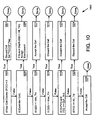
- the SIC 806 follows the steps indicated in Figure 10 to determine whether a cell is to be accepted. In particular, at step 1002, the SIC 806 determines whether there is any free memory available to store the cell. If the free cell counter (FCC) is zero, the cell is discarded (step 1004). Otherwise the SIC 806 determines if the cell is a controller cell (step 1006). If so, if the queue depth (QD) is less than All_Thr, then the cell is accepted, otherwise discarded (step 1008).
- FCC free cell counter
- Step 1010 if the queue depth is less than or equal to the minimum threshold queue size (Min_Thr) then the cell is accepted (step 1012).
- Step 1014 checks to see if the queue depth is greater than the maximum allowed queue size (Max_Thr), and if so the cell is discarded (step 1016).
- the SIC 806 may accept or discard the cell based on the CLP. If the cell is low priority, and the amount of free memory is less than or equal to the cell loss priority threshold (CLP_Thr), then the cell is discarded (step 1020). If (step 1022) the amount of free memory is less than All_Thr, then the cell is discarded (step 1024). Otherwise, the cell is accepted (step 1026).
- the pointer memory 816 stores the thresholds referred to above, including the All_Thr, Min_Thr, Max_Thr, CLP_Thr, and FCC for each queue.
- Figure 11 summarizes a method 1100 for routing data through a satellite to a selected downlink hop location.
- the satellite looks up a hop location destination queue using an address carried in the uplink data.
- the satellite switches the uplink data through a switch, and stores (step 1106) the data in the appropriate queue.
- the satellite In building frames for transmission, the satellite, at step 1108, first retrieves data from the queue in order to build the downlink waveform. The satellite then selects a feed path for the waveform according to its destination hop location (step 1110). The waveform is transmitted (step 1112), preferably using a multiple beam array antenna with feed elements assigned to the hop locations.
- the external cell memory 804 may also include a queue dedicated to controller cells.
- the downlink scheduling table services the controller cells by placing them in a controller buffer (as opposed to preparing them for transmission in a downlink frame), for example, 32 or 64 cells in size.
- One or more control elements may then access the controller buffer, decode commands in the cell, and perform those commands.
- a controller cell may direct an inbound module to replace entries in the routing table 702.
- the present invention provides a beam hopping self addressed packet switched communication system.
- the communication system shares a multiport memory between output ports of a cell switch (and therefore between downlink beams).
- the multiport shared memory architecture increases throughput by 5% or more, and additionally increases memory utlization itself by 30% or more. Additional increases in memory utilization and throughput may be realized by sharing the multiport memory between additional output ports of the cell switch 608 (and therefore additional hop locations).
- the extensive set of queues provide storage for cells of many different priorities, hop locations, and coding rates. Cell acceptance algorithms enforce, for example, minimum bandwidth capability for each queue, maximum size constraints for each queue, and the like.
Landscapes
- Engineering & Computer Science (AREA)
- Computer Networks & Wireless Communication (AREA)
- Signal Processing (AREA)
- Physics & Mathematics (AREA)
- Astronomy & Astrophysics (AREA)
- Aviation & Aerospace Engineering (AREA)
- General Physics & Mathematics (AREA)
- Radio Relay Systems (AREA)
- Data Exchanges In Wide-Area Networks (AREA)
Applications Claiming Priority (2)
| Application Number | Priority Date | Filing Date | Title |
|---|---|---|---|
| US59903500A | 2000-06-21 | 2000-06-21 | |
| US599035 | 2000-06-21 |
Publications (2)
| Publication Number | Publication Date |
|---|---|
| EP1168669A2 true EP1168669A2 (fr) | 2002-01-02 |
| EP1168669A3 EP1168669A3 (fr) | 2004-01-28 |
Family
ID=24397925
Family Applications (1)
| Application Number | Title | Priority Date | Filing Date |
|---|---|---|---|
| EP01113509A Withdrawn EP1168669A3 (fr) | 2000-06-21 | 2001-06-11 | Système de communication à commutation de paquets auto-adressés avec saut de pinceaux d'antenne et mémoire partagée à ports multiples |
Country Status (3)
| Country | Link |
|---|---|
| EP (1) | EP1168669A3 (fr) |
| JP (1) | JP2002051084A (fr) |
| CA (1) | CA2351011A1 (fr) |
Cited By (2)
| Publication number | Priority date | Publication date | Assignee | Title |
|---|---|---|---|---|
| WO2007129287A1 (fr) * | 2006-05-09 | 2007-11-15 | Fleetmatics Patents Limited | Systeme de reperage de vehicule |
| US7388518B2 (en) | 2006-05-09 | 2008-06-17 | Fleetmatics Patents Limited | Vehicle tracking system |
Family Cites Families (4)
| Publication number | Priority date | Publication date | Assignee | Title |
|---|---|---|---|---|
| US5596722A (en) * | 1995-04-03 | 1997-01-21 | Motorola, Inc. | Packet routing system and method for achieving uniform link usage and minimizing link load |
| CA2202116C (fr) * | 1996-07-18 | 2000-08-01 | Liang Hsu | Systeme de transmission de paquets de donnees amdc a satellite utilisant le multiplexage temporel |
| US6175719B1 (en) * | 1997-06-25 | 2001-01-16 | Hughes Electronics Corporation | Multi-spot-beam satellite system with broadcast and surge capacity capability |
| US6205319B1 (en) * | 1998-09-18 | 2001-03-20 | Trw Inc. | Dual phased-array payload concept |
-
2001
- 2001-06-11 EP EP01113509A patent/EP1168669A3/fr not_active Withdrawn
- 2001-06-19 CA CA 2351011 patent/CA2351011A1/fr not_active Abandoned
- 2001-06-21 JP JP2001188027A patent/JP2002051084A/ja active Pending
Cited By (2)
| Publication number | Priority date | Publication date | Assignee | Title |
|---|---|---|---|---|
| WO2007129287A1 (fr) * | 2006-05-09 | 2007-11-15 | Fleetmatics Patents Limited | Systeme de reperage de vehicule |
| US7388518B2 (en) | 2006-05-09 | 2008-06-17 | Fleetmatics Patents Limited | Vehicle tracking system |
Also Published As
| Publication number | Publication date |
|---|---|
| CA2351011A1 (fr) | 2001-12-21 |
| JP2002051084A (ja) | 2002-02-15 |
| EP1168669A3 (fr) | 2004-01-28 |
Similar Documents
| Publication | Publication Date | Title |
|---|---|---|
| US6377561B1 (en) | Data communication satellite system and method of carrying multi-media traffic | |
| US6628919B1 (en) | Low-cost multi-mission broadband communications payload | |
| AU2012347621B2 (en) | Interference management in a hub-spoke spot beam satellite communication system | |
| US10313001B2 (en) | Hybrid processor with switching control based on dynamic bandwidth allocation for multi-beam satellite systems | |
| US7925208B2 (en) | Multi-spot-beam satellite system with broadcast and surge capacity capability | |
| US7068974B1 (en) | Beam hopping self addressed packet switched communication system with power gating | |
| US6944140B1 (en) | Beam hopping self addressed packet switched communication system with multiple beam array antenna | |
| EP1417807B1 (fr) | Mecanisme d'acces multiple a reservation de rafale avec attribution de bande passante libre et a la demande | |
| EP1168664B1 (fr) | Système de communication par paquets auto-adressés avec saut de pinceaux d'antenne et allocation locale intelligente de trame | |
| EP1168672A2 (fr) | Agencement de faisceaux multiples d'antenne de satellite avec bandes commutables pour des liaisons satellitaires descendantes avec saut de fréquence | |
| EP1168669A2 (fr) | Système de communication à commutation de paquets auto-adressés avec saut de pinceaux d'antenne et mémoire partagée à ports multiples | |
| US7426386B1 (en) | Beam laydown for hopped satellite downlink with adaptable duty cycle | |
| US6941108B2 (en) | VSAT station and VSAT communication system | |
| EP1158700A2 (fr) | Algorithme de planification basé sur des tableaux pour une allocation de bande passante pour une liaison satellite descendente | |
| EP1158701A2 (fr) | Dispositif pour contôler le routage dans un système de communications satellitaire | |
| JP2001196992A (ja) | 衛星通信システム | |
| Stern et al. | Next generation communications satellites: Multiple access and network studies |
Legal Events
| Date | Code | Title | Description |
|---|---|---|---|
| PUAI | Public reference made under article 153(3) epc to a published international application that has entered the european phase |
Free format text: ORIGINAL CODE: 0009012 |
|
| AK | Designated contracting states |
Kind code of ref document: A2 Designated state(s): AT BE CH CY DE DK ES FI FR GB GR IE IT LI LU MC NL PT SE TR |
|
| AX | Request for extension of the european patent |
Free format text: AL;LT;LV;MK;RO;SI |
|
| RIN1 | Information on inventor provided before grant (corrected) |
Inventor name: BERA, TUHINA R. Inventor name: YEE-MADERA, GEFFERIE H. Inventor name: NGUYEN, ANDREW T. Inventor name: JUE, REGINALD Inventor name: COOPER, SCOTT A. Inventor name: MOY-YEE, LISA A. Inventor name: LINSKY, STUART T. |
|
| RAP1 | Party data changed (applicant data changed or rights of an application transferred) |
Owner name: NORTHROP GRUMMAN CORPORATION |
|
| RAP1 | Party data changed (applicant data changed or rights of an application transferred) |
Owner name: NORTHROP GRUMMAN CORPORATION |
|
| PUAL | Search report despatched |
Free format text: ORIGINAL CODE: 0009013 |
|
| AK | Designated contracting states |
Kind code of ref document: A3 Designated state(s): AT BE CH CY DE DK ES FI FR GB GR IE IT LI LU MC NL PT SE TR |
|
| AX | Request for extension of the european patent |
Extension state: AL LT LV MK RO SI |
|
| RIC1 | Information provided on ipc code assigned before grant |
Ipc: 7H 04B 7/204 B Ipc: 7H 04B 7/185 A |
|
| AKX | Designation fees paid | ||
| REG | Reference to a national code |
Ref country code: DE Ref legal event code: 8566 |
|
| STAA | Information on the status of an ep patent application or granted ep patent |
Free format text: STATUS: THE APPLICATION IS DEEMED TO BE WITHDRAWN |
|
| 18D | Application deemed to be withdrawn |
Effective date: 20040729 |
|
| RIN1 | Information on inventor provided before grant (corrected) |
Inventor name: BERA, TUHINA R. Inventor name: YEE-MADERA, GEFFERIE H. Inventor name: NGUYEN, ANDREW T. Inventor name: JUE, REGINALD Inventor name: COOPER, SCOTT A. Inventor name: MOY-YEE, LISA A. Inventor name: LINSKY, STUART T. |