EP1169532B1 - Gerüstelemente mit verschlusselement - Google Patents
Gerüstelemente mit verschlusselement Download PDFInfo
- Publication number
- EP1169532B1 EP1169532B1 EP00921289A EP00921289A EP1169532B1 EP 1169532 B1 EP1169532 B1 EP 1169532B1 EP 00921289 A EP00921289 A EP 00921289A EP 00921289 A EP00921289 A EP 00921289A EP 1169532 B1 EP1169532 B1 EP 1169532B1
- Authority
- EP
- European Patent Office
- Prior art keywords
- scaffold
- platform
- locking slide
- locking
- lock position
- Prior art date
- Legal status (The legal status is an assumption and is not a legal conclusion. Google has not performed a legal analysis and makes no representation as to the accuracy of the status listed.)
- Expired - Lifetime
Links
- 238000010276 construction Methods 0.000 description 3
- 239000002184 metal Substances 0.000 description 3
- 230000000694 effects Effects 0.000 description 2
- 230000000007 visual effect Effects 0.000 description 2
- 229910000831 Steel Inorganic materials 0.000 description 1
- 238000013459 approach Methods 0.000 description 1
- 238000005452 bending Methods 0.000 description 1
- 238000006243 chemical reaction Methods 0.000 description 1
- 238000006073 displacement reaction Methods 0.000 description 1
- 239000000463 material Substances 0.000 description 1
- 239000010959 steel Substances 0.000 description 1
Images




Classifications
-
- E—FIXED CONSTRUCTIONS
- E04—BUILDING
- E04G—SCAFFOLDING; FORMS; SHUTTERING; BUILDING IMPLEMENTS OR AIDS, OR THEIR USE; HANDLING BUILDING MATERIALS ON THE SITE; REPAIRING, BREAKING-UP OR OTHER WORK ON EXISTING BUILDINGS
- E04G1/00—Scaffolds primarily resting on the ground
- E04G1/15—Scaffolds primarily resting on the ground essentially comprising special means for supporting or forming platforms; Platforms
- E04G1/154—Non-detachably fixed and secured connections between platform and scaffold
-
- E—FIXED CONSTRUCTIONS
- E04—BUILDING
- E04G—SCAFFOLDING; FORMS; SHUTTERING; BUILDING IMPLEMENTS OR AIDS, OR THEIR USE; HANDLING BUILDING MATERIALS ON THE SITE; REPAIRING, BREAKING-UP OR OTHER WORK ON EXISTING BUILDINGS
- E04G7/00—Connections between parts of the scaffold
- E04G7/02—Connections between parts of the scaffold with separate coupling elements
- E04G7/28—Clips or connections for securing boards
Definitions
- the present invention relates to a scaffold platform comprising a locking device which platform is provided with a number of hook elements which protrude from at least two of the sides of the platform in order to, when mounted, be hooked up on lying scaffold elements in a scaffold, wherein the locking device is adjustable between a release position, in which the platforms can be unhooked from accompanying scaffold elements, and a lock position, in which the platform is locked to the scaffold element, the locking device being constituted by at least one displaceable locking slide which is movable in a guide device between, on the one hand, the release position, in which the accompanying scaffold element can be inserted into and taken out of, respectively, the hook elements and, on the other hand, the lock position, in which the slide blocks the scaffold element in the hook elements, the locking slide being provided with an indication section, which follows the locking slide's adjustment movement between release position and lock position and is adapted to, in release position, protrude clearly visible for an observer from the upper side of the platform for ocular indication that the platform is unlocked.
- scaffold platforms are nowadays used in order to replace planks.
- Scaffold platforms are used in order to uphold individuals and other load in scaffolds, but can be used in a number of situations where temporary, movable scaffolds or stands are used, for example for stage constructions for artist appearances, bridges, landing-stages etc.
- the platforms can be provided with locking devices for locking accompanying hook elements to lying scaffold elements.
- the hook elements are open downwards, for which reason the locking devices, and in particular their active part, are arranged so that they essentially are visible from the under side of the platforms. On assembly, the hook elements are first hooked on to the lying scaffold elements so that the platforms rest on these.
- GB-A-2 218 146 discloses a locking device which has no indication element and requires a tool for its conversion.
- GB-A-2 127 086 discloses a locking device which has a locking slide made by a rod material enclosing a hook element and forming an indication element.
- EP-B-0 659 955 discloses a locking device which has a locking element which is locked by means of a locking wedge.
- the object of the present invention is to provide a scaffold platform comprising a locking device, by means of which the above-mentioned disadvantages are eliminated.
- the guide device discloses two attachment brackets at least one of the brackets disclosing a first planar guide surface against which one side of the locking slide bears with a suitable adjusted friction by means of a spring force, said one side forming a second planar guide surface, the guide device further including a guide pin which extends through an arched guide slit in the locking slide.
- a clear, visible indication of the lock status of the locking device is obtained, which indication is obtained from the upper side of the platform as well, i.e. where users are situated, further having a locking slide guided between lock and release position.
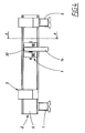
- a locking device 1 is installed on a scaffold platform 2 according to the invention, which is of a type that discloses a number of hook elements 3 that are installed at the ends of the platform, wherein only one of the ends is shown in the drawings.
- a complete platform is generally elongated and commonly discloses two hook elements at each end thereof.
- One single elongated hook element of a profile may possibly extend over a large part of the width of the platform, altematively may several hook elements possibly be arranged, depending on the width of the platform. It is for that matter possible that the hook elements instead or also are arranged along the long sides in a special arrangement in order to provide a high degree of load-bearing capacity.
- the scaffold platform 2 is intended to form part of or to be upheld by a scaffold, of which a lying scaffold element 4 is shown in the drawings.
- a scaffold of which a lying scaffold element 4 is shown in the drawings.
- the scaffold elements 4 are suitably formed by metal pipes, which in the shown example have a circular cross-sectional form, i.e. a uniform transverse dimension with a symmetry axis which also forms a center of curvature.
- the scaffold also includes posts or standing elements which stand on a ground and in turn uphold the lying elements 4.
- a scaffold may consist of a large number of lying elements 4 which are situated on different levels and/or the same level in order to uphold a large number of platforms in a scaffold.
- the platform is made up of two parallel longitudinal profile beams 5, between which longitudinal profile beams transversal profile beams 6 extend at each end. Additional profile beams may also be arranged between the longitudinal profile beams 5.
- the longitudinal profile beams support a platform plane 7, which forms the upper side of the platform.
- the entire construction is made in light metal, which results in a substantial strength in relation to the weight.
- the rest of the scaffold elements, such as the lying scaffold elements 4, are usually pipe constructions, which in the shown example disclose a circular cross-sectional form, but may altematively be square profiles or have another form of profile. These elements may be made either in steel or light metal.
- the hook elements 3 are also constructed out of a hooked profile and disclose a hooked section 8 with a free hook end 9, which in the shown example points downwards in an assembled state, and an inside rest surface 10 which advantageously is adapted to the form and the dimension of the mantle surface 11 of the scaffold element 4, i.e. essentially its arched form.
- the rest surface 10 discloses an extension which in the shown example essentially corresponds to half the periphery of the mantle surface 11, which results in that a hook opening 12 is defined which allows the scaffold element to be inserted into and taken out of, respectively, the hook element.
- the hook element is provided with an attachment bracket 13, by means of which the hook element is fixed to the platform, in this case the profile beam 6.
- the locking device 1 is best apparent from Figs. 3-6.
- the locking device consists of a locking slide 14 or latch, which is movably installed in a guide device 15 for adjustment between a release position for the scaffold element 4 and a lock position, in which the scaffold element is blocked so that the hook elements will not be unhooked.
- the locking slide 14 discloses a curved or bent, arched form, and has an extension which covers at least 90° of a circular arc.
- the locking slide is arc-shapely curved in order to connect to the form of the mantle surface 11 of the lying scaffold element 4.
- the locking slide discloses a concavely curved arc-shaped lock surface 16 and a convexly curved guide surface 17.
- the center of curvature for the locking slide 14 is not entirely coincident with the center of curvature 18 for the lying element, by means of which a locking with freedom from play can be assured between locking slide and scaffold element 4 in lock position, see Fig. 6, i.e. so that the lock surface 16 in the locking direction, i.e. downwards in Fig. 6, approaches the scaffold element 4 and in lock position advantageously partly bears against the mantle surface 11.
- the guide device 15 is adapted to, on the one hand, hold the slide 14 fixed to the platform and, on the other hand, guide its adjustment movements between lock position and release position, and also assure that the locking slide in a secure manner is kept in lock position.
- the guide device discloses two attachment brackets 19, 20, which are fixed to an attachment surface of the transversal profile beam 6 in such manner that they between themselves form a gap which slightly exceeds the width of the locking slide.
- At least one of the attachment brackets discloses a planar guide surface 21, against which the locking slide is intended to bear with one of its sides, which also is planar and forms a guide surface 22.
- the guide device includes a guide pin 23, which extends through the attachment brackets 19, 20 and is kept in place by means of the fact that it suitably is formed as a bolt.
- a spring washer 24 is clamped between one of the attachment brackets 19 and the locking slide 14, the purpose of which is to press the locking slide with freedom from play against the guide surface 21 in the other attachment bracket.
- the guide pin 23 namely extends through an arched guide slit 25 which determines the guide of the locking slide in its adjustment movement between lock position and release position.
- the guide slit 25 has a limited extension and forms in its ends stop bolts for the guide pin in the end positions of the locking slide.
- the adjustment movement is additionally guided by means of two support lists 26, 27 on the profile beam 6 by bearing against the surface 17 of the locking slide.
- the curve of the lock surface 16 is suitably selected so that it has a radius which is less than the radius or half the transverse dimension of the scaffold element 4 or the radius of curvature of the inside rest surface 10 of the hook section 8. The same effect can be obtained by means of the same radius of curvature and a center of curvature for the locking slide 14 which has been shifted inwards.
- the release position for the locking device 1 is shown in Figs. 1, 3, 5 and 7.
- the locking slide is displaced so that the guide pin 23 reaches its end position towards the lower end 28, see Fig 6, of the guide slit 25.
- the locking slide 14 protrudes exceedingly above the platform plane 29, see particularly Figs. 1, 3 and 5. This is partly an effect of an eccentrically situated path at the locking slide.
- the locking slide 14 is, as is shown in the drawings, advantageously radially thicker than the hook element 8 in its section above the scaffold element 4.
- the locking slide protrudes in a distinctly manner in relation to the transversal profile beam 6 as well, see Fig.
- the locking slide forms a visual indication section with one of its ends 30 which is clearly visible for an observer from the upper side of the platform as well, for example for an individual which is situated on the platform, which constitutes a distinct indication of the fact that the platform is not entirely assembled, but that adjustment to lock position is required. Consequently, the first step in the assembly is accomplished by means of the fact that the locking slide in release position is removed in such manner that the hook opening of the hook element allows the scaffold element to be inserted into the hook elements 3.
- lock position is in this regard indicated by means of fact that the indication section 30 is removed from the projection or protrusion position, and is in the shown example situated below the platform plane and protrudes insignificantly from the transversal beam 6 seen from above.
- the guide device allows a displacement movement with a suitably adjusted friction which, apart from the sliding surfaces, is determined by the spring force in the spring washer 24, the purpose of which is to secure that lock position is maintained also during forces which strive to unhook the hook elements 3 from the scaffold element 4.
- a minimum requirement is that the active hook opening 12, which in the lock position of the locking slide has been considerably reduced, is smaller than the transverse dimension of the lying scaffold element 4, i.e. its diameter.
- the active hook opening should be considerably smaller than this dimension in order for component forces on the locking slide not to act to adjust this to release position.
- the locking slide should not be made unnecessarily long in order to avoid bending stresses in this.
- a suitable opening angle in lock position is, for example, as in the shown example, approximately 90°.
- an extremely simple visual or ocular indication is by means of simple means obtained of whether the locking is adjusted to lock position or not.
- a signal colour or a brightly coloured other marking on the locking slide may, for that matter, possibly be arranged on the indication section 30, for example a plastic pin which is bored through the locking slide.
- the guide device can be constructed in a number of different ways, such as in the form of a guide casing in which the locking slide runs.
- the hooked sections 8 can have a rest surface 10 which has another form that is adapted to another cross-sectional form of the scaffold element in question, e.g. polygonal, e.g. quadrangular with sharply or rounded-off corners.
Landscapes
- Engineering & Computer Science (AREA)
- Architecture (AREA)
- Mechanical Engineering (AREA)
- Civil Engineering (AREA)
- Structural Engineering (AREA)
- Ladders (AREA)
- Mutual Connection Of Rods And Tubes (AREA)
- Emergency Lowering Means (AREA)
- Lock And Its Accessories (AREA)
- Preventing Unauthorised Actuation Of Valves (AREA)
- Clamps And Clips (AREA)
- Refuge Islands, Traffic Blockers, Or Guard Fence (AREA)
- Lead Frames For Integrated Circuits (AREA)
Claims (6)
- Gerüstplattform mit einer Arretiereinrichtung (1), bei der die Plattform (2) mit einer Zahl von Hakenelementen (3) versehen ist, die von wenigstens zwei der Seiten der Plattform vorstehen, damit sie bei der Montage auf liegenden Gerüstelementen (4) in einem Gerüst anschließbar sind, wobei die Arretiereinrichtung zwischen einer Freigabestellung, in der die Plattformen von den begleitenden Gerüstelementen gelöst werden können, und einer Verriegelungsstellung, in der die Plattform mit dem Gerüstelement (4) verriegelt ist, einstellbar ist, wobei die Arretiereinrichtung durch wenigstens einen verlagerbaren Arretierschieber (14) gebildet ist, der in einer Führungseinrichtung (15) einerseits zwischen der Freigabestellung, in der das begleitende Gerüstelement jeweils in die Hakenelemente eingesetzt und herausgenommen werden kann, und andererseits der Arretierungsstellung bewegbar ist, in der der Schieber das Gerüstelement in den Hakenelementen blockiert, wobei der Arretierschieber (14) mit einem Anzeigeabschnitt (30) versehen ist, der der Einstellbewegung des Arretierschiebers zwischen der Freigabestellung und der Arretierstellung folgt und für einen Beobachter von der oberen Seite der Plattform zur visuellen Angabe, dass die Plattform entriegelt ist, klar sichtbar vorstehend vorgesehen ist,
dadurch gekennzeichnet, dass die Führungseinrichtung zwei Befestigungsklammern (19, 20) aufweist, wobei wenigstens eine der Klammern eine erste ebene Führungsfläche (21) aufweist, gegen welche eine Seite des arretierenden Schiebers mit einer mittels einer Federkraft geeignet eingestellten Reibung lagert, wobei diese eine Seite eine zweite ebene Führungsfläche (21) bildet, wobei die Führungseinrichtung weiterhin einen Führungsbolzen (23) aufweist, der sich durch einen gekrümmten Führungsschlitz (25) in dem Arretierschieber erstreckt. - Gerüstplattform nach Anspruch 1, dadurch gekennzeichnet, dass die Arretierungseinrichtung (14) gekrümmt und in der Führungseinrichtung (15) längs eines gekrümmten Weges bewegbar ist.
- Gerüstplattform nach Anspruch 1, dadurch gekennzeichnet, dass die radiale Abmessung des Arretierschiebers (14) größer ist als die radiale Abmessung der Hakenelemente, wodurch der Arretierschieber (14) klar sichtbar mit seinem Anzeigeabschnitt oberhalb der Hakenelemente oder der Plattform (2) vorsteht.
- Gerüstplattform nach Anspruch 2, dadurch gekennzeichnet, dass der Arretierschieber (14) für ein geringeres Spiel in der Arretierstellung bezüglich der arretierten Gerüstelemente (4) als das Spiel ausgelegt ist, das in der Freigabestellung auftritt.
- Gerüstplattform nach Anspruch 4, dadurch gekennzeichnet, dass die Krümmungsmitte für den Arretierschieber (14) bezüglich der Krümmungsmitte des liegenden Gerüstelementes (4) exzentrisch ist.
- Gerüstplattform nach Anspruch 3, dadurch gekennzeichnet, dass der Arretierschieber (14) in der Arretierstellung gegen das Gerüstelement (14) anliegt.
Applications Claiming Priority (3)
| Application Number | Priority Date | Filing Date | Title |
|---|---|---|---|
| SE9901259 | 1999-04-09 | ||
| SE9901259A SE521317C2 (sv) | 1999-04-09 | 1999-04-09 | Låsanordning vid ställningsplattformar |
| PCT/SE2000/000667 WO2000061891A1 (en) | 1999-04-09 | 2000-04-07 | Locking device for scaffolding elements |
Publications (2)
| Publication Number | Publication Date |
|---|---|
| EP1169532A1 EP1169532A1 (de) | 2002-01-09 |
| EP1169532B1 true EP1169532B1 (de) | 2005-09-07 |
Family
ID=20415153
Family Applications (1)
| Application Number | Title | Priority Date | Filing Date |
|---|---|---|---|
| EP00921289A Expired - Lifetime EP1169532B1 (de) | 1999-04-09 | 2000-04-07 | Gerüstelemente mit verschlusselement |
Country Status (9)
| Country | Link |
|---|---|
| US (1) | US6530456B1 (de) |
| EP (1) | EP1169532B1 (de) |
| AT (1) | ATE304100T1 (de) |
| AU (1) | AU4162000A (de) |
| DE (1) | DE60022490T2 (de) |
| DK (1) | DK1169532T3 (de) |
| ES (1) | ES2249258T3 (de) |
| SE (1) | SE521317C2 (de) |
| WO (1) | WO2000061891A1 (de) |
Families Citing this family (21)
| Publication number | Priority date | Publication date | Assignee | Title |
|---|---|---|---|---|
| SE518922C2 (sv) * | 2001-04-18 | 2002-12-03 | Pluseight Technology Ab | Hållarkrok för fasthållande av ställningselement vid en byggnadsställning |
| US7051838B1 (en) | 2003-05-22 | 2006-05-30 | Torrey Edd C | Scaffolding system, integral safety rail therefor and methods of making the same |
| DK176257B1 (da) * | 2004-08-11 | 2007-05-07 | Pf Man Holding Aps | Stilladsplanke med aftageligt krogbeslag |
| CA2531430C (en) * | 2005-12-23 | 2013-10-08 | Etobicoke Ironworks Limited | Scaffold deck and self-locking hook |
| ES2267412B1 (es) * | 2006-07-28 | 2007-11-01 | Ingenieria De Encofrados Y Servicios, S.L. | Estructura de soporte para plataformas de trabajo para obras. |
| EP2189592B1 (de) | 2008-11-21 | 2014-12-24 | Haki AB | Verriegelungsvorrichtung für modulares Gerüst oder ähnliches |
| US20110079465A1 (en) * | 2009-10-05 | 2011-04-07 | Waco International Corporation | Multi-Fit Stairway Hook |
| GB201118568D0 (en) * | 2011-10-27 | 2011-12-07 | Web Rigging Services Ltd | Deck panel, load platform and tensioner |
| NL2008120C2 (nl) * | 2012-01-13 | 2013-07-16 | Xsplatforms B V | Steiger. |
| CN102635228B (zh) * | 2012-04-20 | 2014-12-10 | 张雪山 | 一种脚手架扣件式快速连接件 |
| US9410333B2 (en) | 2013-05-21 | 2016-08-09 | Safway Services, Llc | Work platform system including suspended paneled portion and method of implementing same |
| US9976264B2 (en) | 2013-05-21 | 2018-05-22 | Safway Services, Llc | Work platform system including suspended paneled portion and method of implementing same |
| US9388589B2 (en) * | 2013-05-21 | 2016-07-12 | Safway Services, Llc | Work platform system including suspended paneled portion and method of implementing same |
| DE102014222248A1 (de) | 2014-10-31 | 2016-05-04 | Hünnebeck GmbH | Belag für einen Gerüstturm |
| US9777490B2 (en) | 2015-12-11 | 2017-10-03 | Falsework & Shoring Designs, Inc. | Falsework hook and fastener |
| US10676942B2 (en) * | 2016-01-26 | 2020-06-09 | The Boeing Company | Scaffolding apparatus and related methods |
| GB2543933B (en) * | 2016-09-20 | 2017-11-15 | Ischebeck Titan Ltd | Bracket |
| JP3209357U (ja) * | 2016-12-28 | 2017-03-09 | 株式会社Osk | 足場板の固定具 |
| US10532827B2 (en) * | 2017-05-31 | 2020-01-14 | Federal Express Corporation | Modular staircase |
| DE102020107807A1 (de) * | 2019-03-20 | 2020-09-24 | Altrad Plettac Assco Gmbh | Gerüstbauteil |
| NL2033195B1 (nl) | 2022-09-30 | 2024-04-08 | Scafom Holding B V | Opwaaibeveiligingssysteem, vloerdeel, steiger, en gebruik |
Family Cites Families (9)
| Publication number | Priority date | Publication date | Assignee | Title |
|---|---|---|---|---|
| US2997767A (en) * | 1957-01-07 | 1961-08-29 | Werner Co Inc R D | Clamping device for scaffolding |
| FR2083214A1 (de) * | 1971-03-15 | 1971-12-10 | Branchy Pierre | |
| GB2127086B (en) * | 1982-08-20 | 1986-01-29 | Alto Systems Ltd | Automatic latch for use in scaffolding structures |
| GB2174747B (en) * | 1985-05-08 | 1988-10-19 | Alto Systems Ltd | Hook device |
| NL8702026A (nl) * | 1987-08-28 | 1989-03-16 | Beleggingsmaatschappij Bouwmat | Steigerconstructie bestaande uit staanders, kortelingen, en met de kortelingen verbonden platforms. |
| GB8808965D0 (en) * | 1988-04-15 | 1988-05-18 | Ability International Ltd | Locking hook |
| DE9314353U1 (de) | 1993-09-22 | 1993-12-16 | Hans-J. Gebauer GmbH, 56727 Mayen | Arbeitsbühne, vorzugsweise Gerüst zur Einrüstung von Fassaden o.dgl. |
| FR2719066B1 (fr) * | 1994-04-20 | 1996-12-20 | Comabi | Dispositif de plateau pivotant pour échafaudage. |
| DE9410465U1 (de) * | 1994-07-01 | 1995-01-12 | Krause-Werk GmbH & Co KG, 36304 Alsfeld | Verbindungshaken |
-
1999
- 1999-04-09 SE SE9901259A patent/SE521317C2/sv not_active IP Right Cessation
-
2000
- 2000-04-07 AT AT00921289T patent/ATE304100T1/de not_active IP Right Cessation
- 2000-04-07 EP EP00921289A patent/EP1169532B1/de not_active Expired - Lifetime
- 2000-04-07 AU AU41620/00A patent/AU4162000A/en not_active Abandoned
- 2000-04-07 WO PCT/SE2000/000667 patent/WO2000061891A1/en not_active Ceased
- 2000-04-07 ES ES00921289T patent/ES2249258T3/es not_active Expired - Lifetime
- 2000-04-07 DE DE60022490T patent/DE60022490T2/de not_active Expired - Lifetime
- 2000-04-07 US US09/958,396 patent/US6530456B1/en not_active Expired - Lifetime
- 2000-04-07 DK DK00921289T patent/DK1169532T3/da active
Also Published As
| Publication number | Publication date |
|---|---|
| AU4162000A (en) | 2000-11-14 |
| US6530456B1 (en) | 2003-03-11 |
| DE60022490T2 (de) | 2006-07-06 |
| SE9901259L (sv) | 2000-10-10 |
| ATE304100T1 (de) | 2005-09-15 |
| ES2249258T3 (es) | 2006-04-01 |
| SE9901259D0 (sv) | 1999-04-09 |
| WO2000061891A1 (en) | 2000-10-19 |
| DE60022490D1 (de) | 2005-10-13 |
| EP1169532A1 (de) | 2002-01-09 |
| DK1169532T3 (da) | 2006-01-23 |
| SE521317C2 (sv) | 2003-10-21 |
Similar Documents
| Publication | Publication Date | Title |
|---|---|---|
| EP1169532B1 (de) | Gerüstelemente mit verschlusselement | |
| US8579084B2 (en) | Founding system | |
| CA2038992C (en) | Steel post shore, or prop, for supporting of formwork in constructing buildings | |
| EP0408209A2 (de) | Schalungsvorrichtung | |
| US6042074A (en) | Foundation pier coupling system | |
| CA2562364A1 (en) | Beam flange clamp | |
| US6799658B2 (en) | Mobile outrigger scaffolding system | |
| US2916245A (en) | Adjustable scaffold bracket | |
| US8240632B2 (en) | Beam clamp | |
| AU2016208273A1 (en) | Re-positionable Floor Guide System and Tool for use in the same | |
| KR102172875B1 (ko) | 수평조절 및 처짐방지가 가능한 교량 점검로 | |
| EP3880903B1 (de) | Gerüst | |
| US4509711A (en) | Device for detachably supporting a work stand on a wall surface or the like | |
| GB2382614A (en) | Scaffold system mountable on window sill or ledge | |
| AU2008100567A4 (en) | A scaffolding stand for use in a formwork support system | |
| EP4426905A1 (de) | Verriegelungsanordnung für ein gerüstbodenteil, gerüstbodenteil mit der verriegelungsanordnung und verfahren | |
| GB2448199A (en) | Support for scaffolding boards | |
| AU2019101026A4 (en) | Guardrail post | |
| AU2019216711B2 (en) | Guardrail post | |
| KR102441967B1 (ko) | 건축 구조물 | |
| AU751461B1 (en) | Roof safety guardrail system | |
| US20160222681A1 (en) | Turnbuckle clip for use with concrete forming products | |
| EP1857610A1 (de) | Traverse/Boden Verbindung für Gerüstsysteme | |
| CA2594047A1 (en) | Concrete slab depth varying system | |
| GB2638581A (en) | Climbing shoe, pawl device, fastening part and method |
Legal Events
| Date | Code | Title | Description |
|---|---|---|---|
| PUAI | Public reference made under article 153(3) epc to a published international application that has entered the european phase |
Free format text: ORIGINAL CODE: 0009012 |
|
| 17P | Request for examination filed |
Effective date: 20011016 |
|
| AK | Designated contracting states |
Kind code of ref document: A1 Designated state(s): AT BE CH CY DE DK ES FI FR GB GR IE IT LI LU MC NL PT SE |
|
| AX | Request for extension of the european patent |
Free format text: AL;LT;LV;MK;RO;SI |
|
| TPAD | Observations filed by third parties |
Free format text: ORIGINAL CODE: EPIDOS TIPA |
|
| 17Q | First examination report despatched |
Effective date: 20040525 |
|
| RTI1 | Title (correction) |
Free format text: SCAFFOLDING ELEMENTS WITH LOCKING DEVICE |
|
| GRAP | Despatch of communication of intention to grant a patent |
Free format text: ORIGINAL CODE: EPIDOSNIGR1 |
|
| GRAS | Grant fee paid |
Free format text: ORIGINAL CODE: EPIDOSNIGR3 |
|
| GRAA | (expected) grant |
Free format text: ORIGINAL CODE: 0009210 |
|
| AK | Designated contracting states |
Kind code of ref document: B1 Designated state(s): AT BE CH CY DE DK ES FI FR GB GR IE IT LI LU MC NL PT SE |
|
| PG25 | Lapsed in a contracting state [announced via postgrant information from national office to epo] |
Ref country code: NL Free format text: LAPSE BECAUSE OF FAILURE TO SUBMIT A TRANSLATION OF THE DESCRIPTION OR TO PAY THE FEE WITHIN THE PRESCRIBED TIME-LIMIT Effective date: 20050907 Ref country code: LI Free format text: LAPSE BECAUSE OF FAILURE TO SUBMIT A TRANSLATION OF THE DESCRIPTION OR TO PAY THE FEE WITHIN THE PRESCRIBED TIME-LIMIT Effective date: 20050907 Ref country code: CH Free format text: LAPSE BECAUSE OF FAILURE TO SUBMIT A TRANSLATION OF THE DESCRIPTION OR TO PAY THE FEE WITHIN THE PRESCRIBED TIME-LIMIT Effective date: 20050907 Ref country code: AT Free format text: LAPSE BECAUSE OF FAILURE TO SUBMIT A TRANSLATION OF THE DESCRIPTION OR TO PAY THE FEE WITHIN THE PRESCRIBED TIME-LIMIT Effective date: 20050907 Ref country code: BE Free format text: LAPSE BECAUSE OF FAILURE TO SUBMIT A TRANSLATION OF THE DESCRIPTION OR TO PAY THE FEE WITHIN THE PRESCRIBED TIME-LIMIT Effective date: 20050907 Ref country code: FI Free format text: LAPSE BECAUSE OF FAILURE TO SUBMIT A TRANSLATION OF THE DESCRIPTION OR TO PAY THE FEE WITHIN THE PRESCRIBED TIME-LIMIT Effective date: 20050907 |
|
| REG | Reference to a national code |
Ref country code: GB Ref legal event code: FG4D |
|
| REG | Reference to a national code |
Ref country code: CH Ref legal event code: EP |
|
| REG | Reference to a national code |
Ref country code: IE Ref legal event code: FG4D |
|
| REF | Corresponds to: |
Ref document number: 60022490 Country of ref document: DE Date of ref document: 20051013 Kind code of ref document: P |
|
| PG25 | Lapsed in a contracting state [announced via postgrant information from national office to epo] |
Ref country code: GR Free format text: LAPSE BECAUSE OF FAILURE TO SUBMIT A TRANSLATION OF THE DESCRIPTION OR TO PAY THE FEE WITHIN THE PRESCRIBED TIME-LIMIT Effective date: 20051207 Ref country code: SE Free format text: LAPSE BECAUSE OF FAILURE TO SUBMIT A TRANSLATION OF THE DESCRIPTION OR TO PAY THE FEE WITHIN THE PRESCRIBED TIME-LIMIT Effective date: 20051207 |
|
| REG | Reference to a national code |
Ref country code: DK Ref legal event code: T3 |
|
| NLV1 | Nl: lapsed or annulled due to failure to fulfill the requirements of art. 29p and 29m of the patents act | ||
| REG | Reference to a national code |
Ref country code: CH Ref legal event code: PL |
|
| REG | Reference to a national code |
Ref country code: ES Ref legal event code: FG2A Ref document number: 2249258 Country of ref document: ES Kind code of ref document: T3 |
|
| PG25 | Lapsed in a contracting state [announced via postgrant information from national office to epo] |
Ref country code: IE Free format text: LAPSE BECAUSE OF NON-PAYMENT OF DUE FEES Effective date: 20060407 |
|
| PG25 | Lapsed in a contracting state [announced via postgrant information from national office to epo] |
Ref country code: MC Free format text: LAPSE BECAUSE OF NON-PAYMENT OF DUE FEES Effective date: 20060430 |
|
| ET | Fr: translation filed | ||
| PLBE | No opposition filed within time limit |
Free format text: ORIGINAL CODE: 0009261 |
|
| STAA | Information on the status of an ep patent application or granted ep patent |
Free format text: STATUS: NO OPPOSITION FILED WITHIN TIME LIMIT |
|
| 26N | No opposition filed |
Effective date: 20060608 |
|
| REG | Reference to a national code |
Ref country code: IE Ref legal event code: MM4A |
|
| PG25 | Lapsed in a contracting state [announced via postgrant information from national office to epo] |
Ref country code: LU Free format text: LAPSE BECAUSE OF NON-PAYMENT OF DUE FEES Effective date: 20060407 |
|
| PG25 | Lapsed in a contracting state [announced via postgrant information from national office to epo] |
Ref country code: CY Free format text: LAPSE BECAUSE OF FAILURE TO SUBMIT A TRANSLATION OF THE DESCRIPTION OR TO PAY THE FEE WITHIN THE PRESCRIBED TIME-LIMIT Effective date: 20050907 |
|
| PGFP | Annual fee paid to national office [announced via postgrant information from national office to epo] |
Ref country code: PT Payment date: 20120320 Year of fee payment: 13 |
|
| REG | Reference to a national code |
Ref country code: PT Ref legal event code: MM4A Free format text: LAPSE DUE TO NON-PAYMENT OF FEES Effective date: 20131007 |
|
| PG25 | Lapsed in a contracting state [announced via postgrant information from national office to epo] |
Ref country code: PT Free format text: LAPSE BECAUSE OF NON-PAYMENT OF DUE FEES Effective date: 20131007 |
|
| REG | Reference to a national code |
Ref country code: FR Ref legal event code: PLFP Year of fee payment: 17 |
|
| REG | Reference to a national code |
Ref country code: FR Ref legal event code: PLFP Year of fee payment: 18 |
|
| REG | Reference to a national code |
Ref country code: FR Ref legal event code: PLFP Year of fee payment: 19 |
|
| PGFP | Annual fee paid to national office [announced via postgrant information from national office to epo] |
Ref country code: FR Payment date: 20190313 Year of fee payment: 20 |
|
| PGFP | Annual fee paid to national office [announced via postgrant information from national office to epo] |
Ref country code: IT Payment date: 20190419 Year of fee payment: 20 Ref country code: DK Payment date: 20190410 Year of fee payment: 20 Ref country code: DE Payment date: 20190326 Year of fee payment: 20 Ref country code: ES Payment date: 20190503 Year of fee payment: 20 |
|
| PGFP | Annual fee paid to national office [announced via postgrant information from national office to epo] |
Ref country code: GB Payment date: 20190403 Year of fee payment: 20 |
|
| REG | Reference to a national code |
Ref country code: DE Ref legal event code: R071 Ref document number: 60022490 Country of ref document: DE |
|
| REG | Reference to a national code |
Ref country code: DK Ref legal event code: EUP Expiry date: 20200407 |
|
| REG | Reference to a national code |
Ref country code: GB Ref legal event code: PE20 Expiry date: 20200406 |
|
| PG25 | Lapsed in a contracting state [announced via postgrant information from national office to epo] |
Ref country code: GB Free format text: LAPSE BECAUSE OF EXPIRATION OF PROTECTION Effective date: 20200406 |
|
| REG | Reference to a national code |
Ref country code: ES Ref legal event code: FD2A Effective date: 20220127 |
|
| PG25 | Lapsed in a contracting state [announced via postgrant information from national office to epo] |
Ref country code: ES Free format text: LAPSE BECAUSE OF EXPIRATION OF PROTECTION Effective date: 20200408 |