EP1169976B1 - Catheter multi-electrode , système et méthode d'utilisation - Google Patents
Catheter multi-electrode , système et méthode d'utilisation Download PDFInfo
- Publication number
- EP1169976B1 EP1169976B1 EP01305875A EP01305875A EP1169976B1 EP 1169976 B1 EP1169976 B1 EP 1169976B1 EP 01305875 A EP01305875 A EP 01305875A EP 01305875 A EP01305875 A EP 01305875A EP 1169976 B1 EP1169976 B1 EP 1169976B1
- Authority
- EP
- European Patent Office
- Prior art keywords
- electrode
- contact
- reference electrode
- tissue
- catheter
- Prior art date
- Legal status (The legal status is an assumption and is not a legal conclusion. Google has not performed a legal analysis and makes no representation as to the accuracy of the status listed.)
- Expired - Lifetime
Links
- 238000000034 method Methods 0.000 title description 30
- 238000002679 ablation Methods 0.000 claims description 29
- 210000004369 blood Anatomy 0.000 claims description 24
- 239000008280 blood Substances 0.000 claims description 24
- 239000000872 buffer Substances 0.000 claims description 16
- 238000001514 detection method Methods 0.000 claims description 14
- 238000012360 testing method Methods 0.000 claims description 12
- 230000001360 synchronised effect Effects 0.000 claims description 10
- 230000004044 response Effects 0.000 claims description 7
- 238000004891 communication Methods 0.000 claims description 5
- 239000012528 membrane Substances 0.000 claims description 5
- 230000005355 Hall effect Effects 0.000 claims description 2
- 239000012530 fluid Substances 0.000 claims description 2
- 210000001519 tissue Anatomy 0.000 description 62
- 238000013507 mapping Methods 0.000 description 15
- 238000012545 processing Methods 0.000 description 11
- 230000000694 effects Effects 0.000 description 10
- 230000000747 cardiac effect Effects 0.000 description 9
- 238000013461 design Methods 0.000 description 8
- 230000006870 function Effects 0.000 description 8
- 210000005242 cardiac chamber Anatomy 0.000 description 7
- 210000005003 heart tissue Anatomy 0.000 description 7
- 238000010586 diagram Methods 0.000 description 6
- 238000013153 catheter ablation Methods 0.000 description 5
- 238000002847 impedance measurement Methods 0.000 description 5
- 238000012544 monitoring process Methods 0.000 description 5
- 230000001225 therapeutic effect Effects 0.000 description 5
- 210000005166 vasculature Anatomy 0.000 description 5
- 230000003902 lesion Effects 0.000 description 4
- 230000037361 pathway Effects 0.000 description 4
- 206010047302 ventricular tachycardia Diseases 0.000 description 4
- 230000001594 aberrant effect Effects 0.000 description 3
- 230000008901 benefit Effects 0.000 description 3
- 230000007831 electrophysiology Effects 0.000 description 3
- 238000002001 electrophysiology Methods 0.000 description 3
- 229920002635 polyurethane Polymers 0.000 description 3
- 239000004814 polyurethane Substances 0.000 description 3
- 239000000523 sample Substances 0.000 description 3
- 239000004696 Poly ether ether ketone Substances 0.000 description 2
- 230000008859 change Effects 0.000 description 2
- 238000006243 chemical reaction Methods 0.000 description 2
- 230000005672 electromagnetic field Effects 0.000 description 2
- 239000000463 material Substances 0.000 description 2
- 238000005259 measurement Methods 0.000 description 2
- 229920002530 polyetherether ketone Polymers 0.000 description 2
- 230000035945 sensitivity Effects 0.000 description 2
- 239000007787 solid Substances 0.000 description 2
- 238000002560 therapeutic procedure Methods 0.000 description 2
- 238000002604 ultrasonography Methods 0.000 description 2
- 239000004697 Polyetherimide Substances 0.000 description 1
- 230000009471 action Effects 0.000 description 1
- 230000004913 activation Effects 0.000 description 1
- 238000013459 approach Methods 0.000 description 1
- 206010003119 arrhythmia Diseases 0.000 description 1
- 230000004888 barrier function Effects 0.000 description 1
- 210000000988 bone and bone Anatomy 0.000 description 1
- 230000001413 cellular effect Effects 0.000 description 1
- 230000035602 clotting Effects 0.000 description 1
- 230000001143 conditioned effect Effects 0.000 description 1
- 210000002808 connective tissue Anatomy 0.000 description 1
- 230000007423 decrease Effects 0.000 description 1
- 230000002950 deficient Effects 0.000 description 1
- 230000001419 dependent effect Effects 0.000 description 1
- 210000003722 extracellular fluid Anatomy 0.000 description 1
- 238000005286 illumination Methods 0.000 description 1
- 230000000977 initiatory effect Effects 0.000 description 1
- 238000003780 insertion Methods 0.000 description 1
- 230000037431 insertion Effects 0.000 description 1
- 239000011810 insulating material Substances 0.000 description 1
- 238000002955 isolation Methods 0.000 description 1
- 239000007788 liquid Substances 0.000 description 1
- 210000002751 lymph Anatomy 0.000 description 1
- 230000013011 mating Effects 0.000 description 1
- 210000003205 muscle Anatomy 0.000 description 1
- 210000005036 nerve Anatomy 0.000 description 1
- 239000000615 nonconductor Substances 0.000 description 1
- 231100000252 nontoxic Toxicity 0.000 description 1
- 230000003000 nontoxic effect Effects 0.000 description 1
- 229920001601 polyetherimide Polymers 0.000 description 1
- 230000008569 process Effects 0.000 description 1
- 230000009467 reduction Effects 0.000 description 1
- 230000033764 rhythmic process Effects 0.000 description 1
- 230000011664 signaling Effects 0.000 description 1
- 230000001954 sterilising effect Effects 0.000 description 1
- 238000004659 sterilization and disinfection Methods 0.000 description 1
- 238000012546 transfer Methods 0.000 description 1
- 238000011282 treatment Methods 0.000 description 1
- 238000012800 visualization Methods 0.000 description 1
Images








Classifications
-
- A—HUMAN NECESSITIES
- A61—MEDICAL OR VETERINARY SCIENCE; HYGIENE
- A61B—DIAGNOSIS; SURGERY; IDENTIFICATION
- A61B18/00—Surgical instruments, devices or methods for transferring non-mechanical forms of energy to or from the body
- A61B18/04—Surgical instruments, devices or methods for transferring non-mechanical forms of energy to or from the body by heating
- A61B18/12—Surgical instruments, devices or methods for transferring non-mechanical forms of energy to or from the body by heating by passing a current through the tissue to be heated, e.g. high-frequency current
- A61B18/1206—Generators therefor
-
- A—HUMAN NECESSITIES
- A61—MEDICAL OR VETERINARY SCIENCE; HYGIENE
- A61M—DEVICES FOR INTRODUCING MEDIA INTO, OR ONTO, THE BODY; DEVICES FOR TRANSDUCING BODY MEDIA OR FOR TAKING MEDIA FROM THE BODY; DEVICES FOR PRODUCING OR ENDING SLEEP OR STUPOR
- A61M25/00—Catheters; Hollow probes
- A61M25/01—Introducing, guiding, advancing, emplacing or holding catheters
-
- A—HUMAN NECESSITIES
- A61—MEDICAL OR VETERINARY SCIENCE; HYGIENE
- A61B—DIAGNOSIS; SURGERY; IDENTIFICATION
- A61B18/00—Surgical instruments, devices or methods for transferring non-mechanical forms of energy to or from the body
- A61B18/04—Surgical instruments, devices or methods for transferring non-mechanical forms of energy to or from the body by heating
- A61B18/12—Surgical instruments, devices or methods for transferring non-mechanical forms of energy to or from the body by heating by passing a current through the tissue to be heated, e.g. high-frequency current
-
- A—HUMAN NECESSITIES
- A61—MEDICAL OR VETERINARY SCIENCE; HYGIENE
- A61B—DIAGNOSIS; SURGERY; IDENTIFICATION
- A61B18/00—Surgical instruments, devices or methods for transferring non-mechanical forms of energy to or from the body
- A61B18/04—Surgical instruments, devices or methods for transferring non-mechanical forms of energy to or from the body by heating
- A61B18/12—Surgical instruments, devices or methods for transferring non-mechanical forms of energy to or from the body by heating by passing a current through the tissue to be heated, e.g. high-frequency current
- A61B18/14—Probes or electrodes therefor
- A61B18/1492—Probes or electrodes therefor having a flexible, catheter-like structure, e.g. for heart ablation
-
- A—HUMAN NECESSITIES
- A61—MEDICAL OR VETERINARY SCIENCE; HYGIENE
- A61B—DIAGNOSIS; SURGERY; IDENTIFICATION
- A61B17/00—Surgical instruments, devices or methods
- A61B17/00234—Surgical instruments, devices or methods for minimally invasive surgery
- A61B2017/00292—Surgical instruments, devices or methods for minimally invasive surgery mounted on or guided by flexible, e.g. catheter-like, means
- A61B2017/003—Steerable
-
- A—HUMAN NECESSITIES
- A61—MEDICAL OR VETERINARY SCIENCE; HYGIENE
- A61B—DIAGNOSIS; SURGERY; IDENTIFICATION
- A61B18/00—Surgical instruments, devices or methods for transferring non-mechanical forms of energy to or from the body
- A61B2018/00053—Mechanical features of the instrument of device
- A61B2018/00059—Material properties
- A61B2018/00065—Material properties porous
-
- A—HUMAN NECESSITIES
- A61—MEDICAL OR VETERINARY SCIENCE; HYGIENE
- A61B—DIAGNOSIS; SURGERY; IDENTIFICATION
- A61B18/00—Surgical instruments, devices or methods for transferring non-mechanical forms of energy to or from the body
- A61B2018/00315—Surgical instruments, devices or methods for transferring non-mechanical forms of energy to or from the body for treatment of particular body parts
- A61B2018/00345—Vascular system
- A61B2018/00351—Heart
-
- A—HUMAN NECESSITIES
- A61—MEDICAL OR VETERINARY SCIENCE; HYGIENE
- A61B—DIAGNOSIS; SURGERY; IDENTIFICATION
- A61B18/00—Surgical instruments, devices or methods for transferring non-mechanical forms of energy to or from the body
- A61B2018/00636—Sensing and controlling the application of energy
- A61B2018/00642—Sensing and controlling the application of energy with feedback, i.e. closed loop control
- A61B2018/00654—Sensing and controlling the application of energy with feedback, i.e. closed loop control with individual control of each of a plurality of energy emitting elements
-
- A—HUMAN NECESSITIES
- A61—MEDICAL OR VETERINARY SCIENCE; HYGIENE
- A61B—DIAGNOSIS; SURGERY; IDENTIFICATION
- A61B18/00—Surgical instruments, devices or methods for transferring non-mechanical forms of energy to or from the body
- A61B2018/00636—Sensing and controlling the application of energy
- A61B2018/0066—Sensing and controlling the application of energy without feedback, i.e. open loop control
-
- A—HUMAN NECESSITIES
- A61—MEDICAL OR VETERINARY SCIENCE; HYGIENE
- A61B—DIAGNOSIS; SURGERY; IDENTIFICATION
- A61B18/00—Surgical instruments, devices or methods for transferring non-mechanical forms of energy to or from the body
- A61B2018/00636—Sensing and controlling the application of energy
- A61B2018/00773—Sensed parameters
- A61B2018/00875—Resistance or impedance
-
- A—HUMAN NECESSITIES
- A61—MEDICAL OR VETERINARY SCIENCE; HYGIENE
- A61B—DIAGNOSIS; SURGERY; IDENTIFICATION
- A61B18/00—Surgical instruments, devices or methods for transferring non-mechanical forms of energy to or from the body
- A61B18/04—Surgical instruments, devices or methods for transferring non-mechanical forms of energy to or from the body by heating
- A61B18/12—Surgical instruments, devices or methods for transferring non-mechanical forms of energy to or from the body by heating by passing a current through the tissue to be heated, e.g. high-frequency current
- A61B18/1206—Generators therefor
- A61B2018/1246—Generators therefor characterised by the output polarity
- A61B2018/1253—Generators therefor characterised by the output polarity monopolar
-
- A—HUMAN NECESSITIES
- A61—MEDICAL OR VETERINARY SCIENCE; HYGIENE
- A61B—DIAGNOSIS; SURGERY; IDENTIFICATION
- A61B18/00—Surgical instruments, devices or methods for transferring non-mechanical forms of energy to or from the body
- A61B18/04—Surgical instruments, devices or methods for transferring non-mechanical forms of energy to or from the body by heating
- A61B18/12—Surgical instruments, devices or methods for transferring non-mechanical forms of energy to or from the body by heating by passing a current through the tissue to be heated, e.g. high-frequency current
- A61B18/1206—Generators therefor
- A61B2018/1246—Generators therefor characterised by the output polarity
- A61B2018/126—Generators therefor characterised by the output polarity bipolar
-
- A—HUMAN NECESSITIES
- A61—MEDICAL OR VETERINARY SCIENCE; HYGIENE
- A61B—DIAGNOSIS; SURGERY; IDENTIFICATION
- A61B18/00—Surgical instruments, devices or methods for transferring non-mechanical forms of energy to or from the body
- A61B18/04—Surgical instruments, devices or methods for transferring non-mechanical forms of energy to or from the body by heating
- A61B18/12—Surgical instruments, devices or methods for transferring non-mechanical forms of energy to or from the body by heating by passing a current through the tissue to be heated, e.g. high-frequency current
- A61B18/14—Probes or electrodes therefor
- A61B2018/1467—Probes or electrodes therefor using more than two electrodes on a single probe
-
- A—HUMAN NECESSITIES
- A61—MEDICAL OR VETERINARY SCIENCE; HYGIENE
- A61B—DIAGNOSIS; SURGERY; IDENTIFICATION
- A61B18/00—Surgical instruments, devices or methods for transferring non-mechanical forms of energy to or from the body
- A61B18/04—Surgical instruments, devices or methods for transferring non-mechanical forms of energy to or from the body by heating
- A61B18/12—Surgical instruments, devices or methods for transferring non-mechanical forms of energy to or from the body by heating by passing a current through the tissue to be heated, e.g. high-frequency current
- A61B18/14—Probes or electrodes therefor
- A61B2018/1497—Electrodes covering only part of the probe circumference
-
- A—HUMAN NECESSITIES
- A61—MEDICAL OR VETERINARY SCIENCE; HYGIENE
- A61B—DIAGNOSIS; SURGERY; IDENTIFICATION
- A61B18/00—Surgical instruments, devices or methods for transferring non-mechanical forms of energy to or from the body
- A61B18/04—Surgical instruments, devices or methods for transferring non-mechanical forms of energy to or from the body by heating
- A61B18/12—Surgical instruments, devices or methods for transferring non-mechanical forms of energy to or from the body by heating by passing a current through the tissue to be heated, e.g. high-frequency current
- A61B18/14—Probes or electrodes therefor
- A61B18/16—Indifferent or passive electrodes for grounding
- A61B2018/162—Indifferent or passive electrodes for grounding located on the probe body
-
- A—HUMAN NECESSITIES
- A61—MEDICAL OR VETERINARY SCIENCE; HYGIENE
- A61B—DIAGNOSIS; SURGERY; IDENTIFICATION
- A61B34/00—Computer-aided surgery; Manipulators or robots specially adapted for use in surgery
- A61B34/20—Surgical navigation systems; Devices for tracking or guiding surgical instruments, e.g. for frameless stereotaxis
- A61B2034/2046—Tracking techniques
- A61B2034/2051—Electromagnetic tracking systems
Definitions
- the present invention is directed to a novel system for detecting contact of an electrode with tissue.
- the system of the invention is particularly suited for use in conjunction with intracardiac electrophysiology or electromechanical studies or in conjunction with therapeutic procedures such as cardiac ablation.
- VT Cardiac arrhythmias, the most common of which is ventricular tachycardia (VT), are a leading cause of death.
- VT originates from a 1 mm to 2 mm lesion located close to the inner surface of the heart chamber.
- One of the treatments for VT comprises mapping the electrical pathways of the heart to locate the lesion followed by ablation of the active site.
- U.S. patent 5,546,951; U.S. patent application 08/793,371 (now published as US 6,690,693); and PCT application WO 96/05768 disclose methods for sensing an electrical property of heart tissue such as local activation time as a function of the precise location within the heart.
- the data are acquired by advancing into the heart one or more catheters that have electrical and location sensors in their distal tips.
- the precise three-dimensional location of the catheter tip is ascertained by the location sensor contained therein.
- the location sensor operates by generating signals that are responsive to its precise location within an extemally generated non-ionizing field such as an electromagnetic field. Simultaneous with the acquisition of location information, electrical information is also acquired by at least one electrode contained at the catheter distal tip.
- Accurate sensing of location and electrical information by sensors contained in the catheter generally requires a high degree of confidence that a catheter electrode is in contact with the tissue.
- U.S. Patent 5,409,000 discloses the use of a catheter probe having a plurality of flexible, longitudinally extending circumferentially spaced apart arms adapted to be disposed within a chamber of a heart. Electrodes are carried by the arms and are adapted to be moved into engagement with the wall of the heart. Markers visible ultrasonically are carried by the arms for encoding the arms so that one arm can be distinguished from another.
- An ablation catheter having ultrasonic viewing means such as an ultrasonic sensor or transducer at its distal extremity is carried by and is slidably mounted in the catheter probe.
- the distal extremity of the ablation catheter is moveable into positions to view ultrasonically the markers carried by the arms of the catheter probe so that the arms can be identified and the spacing of the arms can be ascertained.
- PCT application WO 99/05971 discloses a system that uses one or more ultrasound reference catheters to establish a fixed, three-dimensional coordinate system within a patient's heart using principles of triangulation.
- the coordinate system is represented graphically in three dimensions on a video monitor and is reported to aid the clinician in guiding other medical devices, which are provided with ultrasound sensors or transducers, through the body to locations at which they are needed to perform clinical procedures.
- the system is reported to be useful to help a physician guide mapping catheters for measuring electrical activity and ablation catheters for ablating selected regions of cardiac tissue, to desired locations within the heart.
- Catheters containing position or location sensors may also be used to determine the trajectory of points on the cardiac surface. These trajectories may be used to infer mechanical motion characteristics such as the contractility of the tissue. As disclosed in U.S. patent 5,738,096, maps depicting such motion characteristics, which may be superimposed with maps depicting local electrical information, may be constructed when the trajectory information is sampled at a sufficient number of points in the heart. Accurate maps of such motion characteristics again require confidence that the data are acquired when the catheter tip is in contact with the cardiac tissue.
- the detailed maps generated as hereinabove described may serve as the basis for deciding on a therapeutic course of action, for example, tissue ablation, to alter the propagation of the heart's electrical activity and to restore normal heart rhythm.
- energy typically in the radiofrequency (RF) range
- RF radiofrequency
- Ablation is effected by bringing the distal tip electrode into contact with the locus of aberrant electrical activity and by initiating the delivery of RF energy through the distal tip electrode from an external RF generator in communication with the distal tip electrode. Ablation is most effectively performed when the distal tip electrode is in contact with the cardiac wall.
- U.S. patents 5,935,079, 5,836,990, and 5,447,529 determine electrode-tissue contact by measuring the impedance between the tip electrode and a return electrode. As disclosed in the '529 patent, it is generally known that impedance through blood is generally lower that impedance through tissue.
- tissue contact has been detected by comparing the impedance values across a set of electrodes to premeasured impedance values when an electrode is known to be in contact with tissue and when it is known to be in contact only with blood.
- a problem in using this method during intracardiac procedures is the fact that tissue and blood impedances may change during a procedure.
- the impedance through tissue also depends on the state of the tissue. For instance, impedance through infarcted tissue is known to be less than the impedance through healthy tissue.
- U.S. patent 5,341,807 discloses a method of detecting contact of a catheter tip electrode with tissue.
- the method of the '807 patent employs a catheter having a tip electrode and a plurality of axially spaced ring electrodes mounted along the catheter surface.
- a test signal is applied across a pair of outer electrodes arranged along the catheter.
- Each outer electrode is paired with an inner electrode to develop a sensing signal characteristic of impedance for the tissue between the electrodes.
- tissue impedance measurement is the sole manner for determining the position and orientation of the catheter.
- the impedance measuring components of the '807 patent would require a separate ground relative to the ECG device, which complicates the circuitry.
- the present invention is directed to a novel system for detecting electrode-tissue contact.
- the present invention is directed to a novel system for detecting contact of an electrode with tissue such as the wall of a chamber of a heart.
- the present invention is particularly suitable for use with systems and methods for mapping the electrical characteristics of a chamber of a heart, or for performing electro-therapeutic procedures such as cardiac ablation.
- the system of the invention for detecting electrode-tissue contact is based on differential impedance measurements. Impedance values of tissue such as the cardiac wall tend to be larger than the impedance of blood.
- the system of the invention measures the impedance between a catheter contact electrode, preferably positioned on the catheter distal tip, and a return electrode.
- the system of the invention also simultaneously measures the impedance between a reference electrode and a return electrode.
- the reference electrode is internal to the body and is preferably prevented from making contact with tissue.
- tissue is meant to describe all solid or semi-solid cellular matter in the body, such as muscle, nerve, connective tissue, vasculature and bone. Blood and other liquid matter, such as lymph, interstitial fluids or other fluids in the body, are excluded from the definition of "tissue” as defined herein.
- the system comprises a catheter 20 for insertion into the human body, and preferably, into a chamber of a human heart 29 (Fig. 2).
- the catheter 20 includes a catheter body 20a having a distal end 22.
- the distal end 22 includes a contact electrode 24 at distal tip 26 for measuring the electrical properties of the heart tissue.
- Contact electrode 24 is also useful for sending electrical signals to the heart for diagnostic purposes, e.g., for pace mapping, and/or for therapeutic purposes, e.g., for ablating defective cardiac tissue.
- contact electrode 24 is designed to be in contact with tissue when performing its functions of receiving electrical signals from and transmitting electrical signals to the heart, it should be understood that contact electrode 24 is not always in contact with tissue. For example, contact electrode 24 may not be in contact with tissue as it is being advanced through the vasculature to the heart, or when it is being directed from one point to another point within the heart chamber. Accordingly, it is an object of the system and method of the invention to detect contact of the contact electrode with tissue.
- Distal end 22 of catheter 20 further includes reference electrode 25 for providing an internal reference measurement of impedance while the reference electrode 25 is in contact with blood but is not in contact with tissue.
- Distal end 22 of catheter 20 further includes a location sensor 28 that generates signals used to determine the position and orientation of the catheter within the body.
- Location sensor 28 is preferably adjacent to distal tip 26 of catheter 20. There is preferably a fixed positional and orientational relationship of location sensor 28, tip 26 and electrode 24.
- Catheter 20 preferably includes a handle 30, which includes controls 32 to steer the distal end 22 of the catheter 20 in a desired direction, such as deflecting the distal end 22, or to position and/or orient it as desired.
- the system 18, as shown in Figures 1 and 2, further comprises a console 34, which enables the user to observe and regulate the functions of catheter 20.
- Console 34 preferably includes a computer 36, keyboard 38, and display 42.
- Computer 36 contains control circuits to permit control and operation of the system and to start and stop the collection of data from the catheter's tip electrode 24, reference electrode 25 and from location sensor 28.
- Computer 36 further uses the electrical and or mechanical and location information acquired by catheter electrodes 24 and 25 and location sensor 28 and processed by signal processing circuits 40 in reconstruction and visualization of an electrical or electromechanical map of a chamber of the heart.
- Signal processing circuits 40 typically receive, amplify, filter and digitize signals from catheter 20, including signals generated by location sensor 28, tip electrode 24 and reference electrode 25. Circuits 40 further compute the position and orientation of the catheter as well as the electrical characteristics of the heart chamber from the signals generated by location sensor 28 and tip electrode 24. Circuits 40 also process body surface electrocardiogram signals. The digitized signals generated by signal processing circuits 40 are received and used by computer 36 to reconstruct and visualize an electrical or electromechanical map of the heart chamber. Circuits 40 also contain contact detection circuitry, including a signal generator 56 (Fig. 3) which sends test signals to tip electrode 24, reference electrode 25 and return electrode 48, as well as circuitry to measure the differential electrical response to these test signals. Return electrode 48 is coupled to circuits 40 via cable 49 wherein return electrode 48 functions as a sink for the test signals.
- return electrode 48 When applied external to the patient's body 110 as shown in Fig. 2, return electrode 48 is preferably relatively large to provide low impedance between the return electrode 48 and the body 110.
- Electrosurgical Patient Plate model 1149F supplied by 3M of St. Paul, Minnesota, which has an area of approximately 130 cm 2 , may be satisfactorily used as the return electrode in the system of the invention.
- circuitry may be associated with the catheter 20 itself so that circuits 40 receive signals that are already arnplified, filtered and/or digitized.
- Catheter 20 is coupled to circuits 40 via an extension cable 21, which at its proximal end comprises a connector 44 adapted to fit in a mating receptacle 46 on circuits 40.
- the distal end of cable 21 comprises a receptacle 33 which connects to catheter handle 30.
- Receptacle 33 is preferably configured to receive catheters of a specific model, and preferably includes user-evident identification of the specific model.
- One of the advantages in using cable 21 is the ability to connect different models and types of catheters, such as those catheters having different handle configurations, to the same circuits 40. Different cables 21 can be used to connect a large variety of catheters to circuits 40.
- Another advantage in having a separate cable 21 is in the fact that the cable 21 does not come into contact with patients and therefore it is possible to re-use the cable 21 without sterilization.
- Circuits 40 contain an isolation barrier to electrically isolate all parts of the system in contact with the patient from console 34. Data transfer from circuits 40 to computer 36 is effected using such devices as insulating transformers, optocouplers and the like.
- FIG. 2 Additional components used in system 18 with catheter 20 of the present invention are illustrated schematically in Fig. 2.
- a physician 51 inserts catheter 20 through an incision in the vasculature, e.g., using an intravascular approach, into a chamber of a heart 29 of a patient 110, so that distal tip electrode 24 and location sensor 28 are inside the chamber.
- sensor 28 generates signals in response to externally applied magnetic fields generated by electromagnetic field generator coils 27 fixed to operating table 31 in proximity to patient 110. The magnitude of the signals generated by sensor 28 depends on the position and orientation of the sensor in the applied magnetic field.
- Field generator coils 27 are connected via cable 41 to driver circuits which are part of signal processing circuits 40. Circuits 40 are connected to computer 36 (Fig. 1) via cable 43.
- Computer 36 controls the operation of the generator coils 27 and the overall system 18.
- system of the invention may employ field generator coils in the catheter and sensors external to the patient.
- the system of the invention may employ catheters of different designs.
- the tip electrode may be of a unipolar or a bipolar design. In the bipolar configuration, the catheter would have another ring electrode proximal to the tip electrode.
- the catheter may have a plurality of ring electrodes along its length.
- any other location sensor that provides three-dimensional position information and, optionally, orientation information may be used in the practice of the invention.
- Illustrative sensors that are also useful include acoustic sensors and magnetic sensors.
- acoustic sensors of the type disclosed in U.S. Patent 5,409,000 and in PCT application WO 99/05971 may be used in accordance with the system of the invention.
- mapping the electrical activity of the heart is performed by positioning the distal tip 26 of catheter 20 at a site within the heart, sensing location and electrical information at the site, processing the sensed location and electrical information at the site to create a data point, and repeating these steps a sufficient number of times to create a map of the heart's electrical pathways.
- location and electrical data are preferably sensed when the tip electrode 24 is in contact with the cardiac wall at each site.
- the aberrant pathway may be treated by ablating the intracardiac surface at the lesion site.
- ablation is typically performed by supplying RF energy to the site from ablation power source 53 via circuits 40 and cable 21 to tip electrode 24 at distal end 22 of catheter 20. Ablation is most effectively performed when tip electrode 24 is in contact with the cardiac wall. Absence of contact or poor contact of tip electrode 24 with the heart wall leads to dissipation of the RF energy in the blood, as well as possible fouling of the tip electrode. Accordingly, it is important that both mapping and ablation be accompanied by methods and systems for detecting electrode-tissue contact.
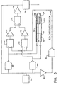
- FIG. 3 One embodiment of a circuit for detecting electrode-tissue contact in conjunction with the system of Fig. 1 is shown in Fig. 3.
- Distal end 22 of catheter 20 is shown in longitudinal cross-section.
- Tip electrode 24, reference electrode 25 and location sensor 28 are connected by wires 50, 52 and 54, respectively, to catheter handle 30 from which electrical connections are made to signal processing circuits 40.
- Signal generator 56 contained within circuits 40, sends a high frequency alternating current (AC) signal, preferably in the frequency range of about 10 kHz to about 100 kHz, to distal tip contact electrode 24 and to reference electrode 25 via high output impedance buffers 58 and 60, respectively.
- a signal frequency of about 50 kHz is most preferred.
- the current to distal tip electrode 24 is equal to the current to reference electrode 25.
- Return electrode 48 is also driven by signal generator 56.
- the signal to return electrode 48 is first inverted in phase by inverter 62 and conditioned by high output impedance buffer 64.
- the current of the signals driving tip electrode 24, reference electrode 25 and return electrode 48 should be below the level that would stimulate cardiac tissue. At 50 kHz, generally accepted safety standards dictate that the current should not exceed 0.5 milliamps (See for example CEI IEC 601-1, Medical Electrical Equipment Part 1 - General Requirements for Safety, Bureau Central de la Commission Electrotechnique Internationale, Geneva Switzerland, 1988).
- First differential amplifier 66 measures a difference signal, specifically, the voltage across distal tip electrode 24 and return electrode 48.
- a second differential amplifier 68 is used to measure the voltage across reference electrode 25 and return electrode 48.
- Signals from differential amplifiers 66 and 68 are further amplified by amplifiers 70 and 72, respectively.
- the outputs of amplifiers 70 and 72 are, in turn, fed to differential amplifier 74.
- the differential output signal from differential amplifier 74 is further amplified by amplifier 76.
- the amplified signal from amplifier 76 is then sent to synchronous detector 78, which transforms the AC signal to a direct current (DC) signal and also decreases the sensitivity of the system to external noise.
- the signal from the synchronous detector 78 is then used by signal processing circuits 40.
- the ratio of the gains of amplifiers 70 and 72 are preferably adjusted so as to be proportional to the ratio of the areas of tip electrode 24 and reference electrode 25. Under these conditions, i.e., when distal tip electrode 24 and reference electrode 25 are both in blood and not in contact with tissue and when the amplifier gains are adjusted as described above, the signals leaving amplifiers 70 and 72 will be of equal voltage and the output of differential amplifier 74 and amplifier 76 will be a null signal of zero volts.
- tip electrode 24 When tip electrode 24 is brought into contact with tissue such as the cardiac wall, which has a higher impedance than blood, and when reference electrode 25 remains in the blood and does not contact the tissue, the voltage across tip electrode 24 and return electrode 48 will exceed the voltage across reference electrode 25 and return electrode 48, resulting in a non-zero voltage signal from differential amplifier 74 and amplifier 76.
- This non-zero signal which detects the change in the impedance across catheter tip electrode 24 and return electrode 48 when tip electrode 24 contacts tissue, is used by the system electronics of signal processing circuits 40 to provide an audible or visible signal indicative of tissue contact.
- Tissue contact is signaled by a variety of techniques.
- One form of signaling of tissue contact for example, is the illumination of a light or LED on an instrument panel.
- tissue contact may be signaled by a meter, displayed on a computer monitor for example, along with other system parameters.
- reference electrode 25 is positioned on mapping/ablation catheter 22 comprising distal tip electrode 24 and location sensor 28.
- reference electrode 25 may be positioned on a separate catheter contained in the vasculature.
- Fig. 13A shows a schematic view of a catheter 20 of an alternate design for use in the system of the invention. Catheter 20 of Fig. 13A does not contain a reference electrode. In use in the system of the invention, a reference electrode would be provided with a second catheter (not shown). Likewise, return electrode 48 may be incorporated on the catheter 20 containing the distal tip electrode 24 and location sensor 28, in which case return electrode 48 would be present in the body during use.
- Fig. 13B shows a schematic view of a catheter 20 of an alternate design which incorporates both a reference electrode 25 and a return electrode 48.
- catheter 20 may be equipped with a thermocouple at distal tip electrode 24 for monitoring of the electrode temperature during ablation and for control of ablation energy delivery to the electrode during ablation.
- return electrode 48 driven by signal generator 56.
- return electrode 48 may be connected to an isolated ground, for example, of an electrocardiogram (ECG) device.
- ECG electrocardiogram
- the right leg ECG electrode is typically connected in many ECG devices to isolated ground, and would function satisfactorily as a return electrode in the system and method of the invention.
- FIG. 5 and Fig. 6 Additional embodiments of circuits for detecting electrode-tissue contact are illustrated in Fig. 5 and Fig. 6.
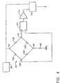
- the circuits of these embodiments may be best understood by first considering the circuit shown in Figure 4, in which signal generator 90 is connected to first input 92 of bridge circuit 94. Second input 96 of bridge circuit 94 is connected to isolated ground via resistor 98. Bridge 94 is composed of a first resistor (R1) 100, a second resistor (R2) 102, a third resistor (R3) 104 and a fourth resistor (R4) 106.
- First bridge output 108 and second bridge output 110 are connected to differential amplifier 112 for measurement of the output voltage of the circuit.
- the signal from differential amplifier 112 is further amplified in amplifier 114, from which it is passed to synchronous detector 116.
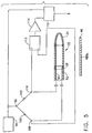
- Fig. 5 illustrates one embodiment of a bridge circuit used to detect electrode-tissue contact in the system of the invention.
- the system uses the same catheter as described with reference to Fig. 3.
- third resistor R3 (104 of Fig. 4) has been replaced by the signal path from reference electrode 25 to return electrode 48
- fourth resistor R4 (106 of Fig. 4) has been replaced by the signal path from distal tip contact electrode 24 to return electrode 48.
- Resistor 98 in Fig. 4 is replaced by the signal path from the skin to external return electrode 48.
- Return electrode 48 is preferably connected to isolated ground, as, for example, to an ECG device isolated ground.
- location sensor 28 is not shown in the catheters of Figures 5, 6 and 7.
- both the tip electrode 24 and reference electrode 25 are in the blood and if both electrodes have the same area, then the impedance from tip electrode 24 to return electrode 48 will equal the impedance from reference electrode 25 to return electrode 48. Under these conditions and if the resistance of resistor R1 100 is equal to the resistance of resistor R2 102, the bridge will have a null output voltage. Contact of tip electrode 24 with tissue having higher impedance than blood will cause the impedance from tip electrode 24 to return electrode 48 to increase over the impedance from reference electrode 25 to return electrode 48, resulting in a non-zero voltage signal from differential amplifier 112, amplifier 114 and synchronous detector 116.
- resistors R1 and R2 have equal resistance and distal tip electrode 24 and reference electrode 25 have unequal surface areas
- the impedance along the individual legs of the circuit will be inversely proportional to the area of the respective electrodes.
- the bridge will not have a null output voltage when both tip electrode 24 and reference electrode 25 are in blood and neither electrode is in contact with tissue.
- the resistance of resistors 100 and 102 is adjusted so as to produce a null signal from differential amplifier 112 when distal tip electrode 24 and reference electrode 25 are both in blood and neither electrode is in contact with tissue. This adjustment is achieved when the ratio of resistances of resistor 100 to resistor 102 is proportional to the ratio of the area of tip electrode 24 to the area of reference electrode 25.
- the impedance of resistors 100 and 102 be at least equal to or greater than the impedance from reference electrode 25 to return electrode 48 and from the distal tip electrode 24 to reference electrode 48.
- the impedance of resistors 100 and 102 should be at least about ten times, and, more preferably, at least about 100 times the impedance across reference electrode 25 to return electrode 48 and across tip electrode 24 to return electrode 48.
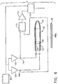
- Fig. 6 shows another embodiment of a bridge circuit used to detect tissue contact in the system and method of the invention.
- resistors 100 and 102 of Fig. 5 are replaced by high output impedance buffers 120 and 122.
- Buffers 120 and 122 convert the constant voltage signal from signal generator 90 to a constant current signal.
- the tip electrode 24 to return electrode 48 impedance will equal the reference electrode 25 to return electrode 48 impedance.
- the bridge will have a null output voltage.
- tip electrode 24 Contact of tip electrode 24 with tissue having higher impedance than blood will cause the tip electrode 24 to return electrode 48 impedance to increase over the reference electrode 25 to return electrode 48 impedance, resulting in a non-zero voltage signal from differential amplifier 112, amplifier 114 and synchronous detector 116.
- the tip electrode 24 to return electrode 48 impedance and reference electrode 25 to return electrode 48 impedance will be inversely proportional to the area of the respective electrodes when tip electrode 24 and reference electrode 25 are both in a common medium.
- the output currents of high output impedance buffers 120 and 122 are a function of the conversion functions of the individual buffers.
- the conversion functions of buffers 120 and 122 are adjusted so as to produce a null signal from differential amplifier 112 when the distal tip electrode 24 and the reference electrode 25 are both in blood and neither electrode is in contact with tissue. This adjustment is achieved when the ratio of the output current from buffer 120 to the output current from buffer 122 is proportional to the ratio of the area of tip electrode 24 to the area of reference electrode 25.
- the impedance of buffers 120 and 122 is preferably at least about one thousand times the body impedances displayed across tip electrode 24 to return electrode 48 and across reference electrode 25 to return electrode 48.
- Fig. 7 depicts yet another embodiment of a circuit for detecting electrode-tissue contact.
- a high frequency signal is supplied directly to catheter distal tip contact electrode 24 and to reference electrode 25.
- Current sensors 130 and 132 monitor the current to reference electrode 25 and to tip electrode 24, respectively.
- Current sensors may be of any type known in the art. For example, current transformers and Hall effect sensors may be used in the practice of the system and method of the invention.
- Output voltage signals of current sensors 130 and 132 are fed to differential amplifier 112 to measure the relative currents to reference electrode 25 and to tip electrode 24.
- the output signal from differential amplifier 112 is further amplified by amplifier 114 and transmitted to synchronous detector 116.
- tip electrode 24 and reference electrode 25 are both in blood, if neither electrode is in contact with tissue and if both electrodes have the same surface area, then the tip electrode 24 to return electrode 48 impedance will equal the reference electrode 25 to return electrode 48 impedance. Under these conditions the current measured by current sensor 130 will equal the current measured by current sensor 132, and differential amplifier 112 will produce a null voltage. Contact of tip electrode 24 with tissue having higher impedance than blood will cause the tip electrode 24 to return electrode 48 impedance to increase over the reference electrode 25 to return electrode 48 impedance, which will, in turn, result in lower current to distal tip electrode 24 relative to reference electrode 25. Reduction in the current to tip electrode 24 relative to reference electrode 25 will result in a non-zero voltage signal from differential amplifier 112, amplifier 114 and synchronous detector 116.
- the tip electrode 24 to return electrode 48 impedance and the reference electrode 25 to return electrode 48 impedance, and hence the output voltages of current sensors 130 and 132 will be inversely proportional to the area of the respective electrodes when tip electrode 24 and reference electrode 25 are both in a common medium and neither electrode is in contact with tissue.
- the output voltages of sensors 130 and 132 are adjusted so as to produce a null signal from differential amplifier 112 when both the distal tip electrode 24 and the reference electrode 25 are in blood and neither electrode is in contact with tissue. This adjustment is achieved when the ratio of the gain of sensor 130 to the gain of sensor 132 is proportional to the ratio of the area of tip electrode 24 to the area of reference electrode 25.
- Reference electrode 25 is preferably protected from making contact with tissue.
- One manner of protecting reference electrode 25 from contacting tissue is to cover reference electrode 25 with a porous or semi-permeable membrane 150 (Fig. 8A).
- the membrane 150 in the form of a sleeve covering the reference electrode 25, permits contact of the reference electrode 25 with blood but prevents contact with tissue.
- the catheter body 20a is made of a non-conducting, non-toxic material such as polyurethane, polyetherimide or polyetherether ketone (PEEK).
- the reference electrode 25 may be protected from contact with tissue by being contained in channel 155 on catheter body 20a.
- the method of the invention may be employed by introducing catheter 20 into the body through an incision of the vasculature. Catheter 20 is then advanced into or proximate to the tissue of interest, for example, into a chamber of the heart.
- the system and method of the invention of detecting electrode-tissue contact may be employed in an intermittent, or, preferably, in a continuous manner.
- the method of the invention may be employed while recording intracardiac electrograms with tip electrode 24.
- ECG signals are typically in the frequency range from about 0.05 Hz to about 500 Hz.
- the contact-testing signals sent to tip electrode 24 by signal generator 56 or 90 are typically in the frequency range of about 10 kHz to about 100 kHz.
- the electrocardiogram information may be decoupled from the contact-testing signal by using a suitable band pass filter.
- the system and method of the invention may be used in creating an electrical map of a chamber of a heart as disclosed in U.S. patent 5,546,951; U.S. patent application 08/793,371 (now published as US 6,690,693), and PCT application WO 96/05768. They may also be used in the generation of a mechanical or electromechanical map of a chamber of a heart as disclosed in U.S. patent 5,738,096.
- data acquisition may be controlled so that location and electrical information are not acquired unless the tip electrode is determined to be in contact with tissue.
- the ablation power source may be interlocked with the contact detection system so that ablation energy is only supplied to the tip electrode when contact of the tip electrode with tissue is detected.
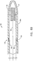
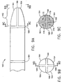
- FIGS. 9A, 9B, 9C and 9D show an alternate distal end embodiment of the catheter 20 for use in the system of the invention.
- Catheter 20 has a distal end 160 which comprises a distal tip electrode assembly 162.
- Distal tip electrode assembly 162 comprises a plurality of individual distal tip electrodes 164 at distal tip 166.
- Each individual distal tip electrode 164 in electrode assembly 162 is electrically insulated from the other individual distal tip electrodes by non-conductor 168, which may be comprised of a material such as polyurethane, for example.
- Each individual distal tip electrode 164 has a lead bore hole 170 in which a lead is soldered for communication with the control and data acquisition circuitry.
- the catheter 20 includes four leads for connection with the four individual distal tip electrodes (two of the four leads, 172 and 174, are shown in Fig. 9D).
- Distal.end 160 of catheter 20 also comprises a location sensor 180 which is connected to signal processing circuits 40 via lead 182, as well as reference electrode 184 which communicates with signal processing circuits 40 via lead 186.
- electrode assembly 162 comprises four individual distal tip electrodes 164 at four distinct quadrants.
- the electrode assembly at catheter distal tip 166 may comprise fewer or greater than four individual distal tip electrodes.
- a system 200 is used for mapping the electrical activity of a chamber of a heart and for performing therapeutic ablation using a multi-electrode catheter of the type shown in Figs. 9A-9D and a contact detecting circuit of the type shown in Figs. 3 - 7.
- System 200 consists of four channels 202, 204, 206 and 208. Each channel is in communication with one of the individual distal tip electrodes 164 on distal end 160 of catheter 20 via leads 224, 226, 228 and 230.
- controller 210 commands multiplexer 212 to switch between channels 202 through 208 to permit differential impedance measurements across each of the individual tip electrodes 164 and the return electrode 48 by contact detection circuit 214.
- contact detection circuit 214 communicates with reference electrode 184 via lead 225 and with return electrode 48 via lead 227.
- Contact detection circuit 214 may contain any of the circuitry shown in Figures 3 through 7. The signal generator associated with contact detection circuit 214 sequentially sends a contact detection signal through multiplexer 212 to each of the distal tip electrodes 164.
- Differential signals are measured across each of the individual tip electrodes 164 and the return electrode 48, and these differential signals are compared by contact detection circuit 214 to the differential signals across reference electrode 184 to the return electrode 48. Detection of tissue contact by each individual tip electrode 164 is accomplished as hereinabove described.
- controller 210 commands multiplexer 216 to selectively close switching circuits and to permit ablation energy to flow from ablation power source 218 to those electrodes 164 determined in the first mode to be in contact with tissue.
- the system 200 selectively ablates at each selected tip electrode 164, i.e. only at those tip electrodes 164 that are in contact with tissue.
- System 200 also contains electrocardiogram (ECG) monitoring and recording circuitry 220 to permit monitoring and recording of electrograms from each distal tip electrode 164.
- ECG circuitry 220 also contains provisions for monitoring and recording external body contact electrograms from external body surface leads 222.
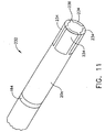
- Fig. 11 shows another alternative embodiment of a distal end 232 of the catheter 20 containing a segmented distal tip electrode 236 for use in the system of the invention.
- the catheter distal tip 236 contains four individual distal tip electrodes 234 equiangularly spaced about the circumference of catheter distal tip 236.
- Each electrode 234 has a portion located on the distal tip of distal end 232 and a longitudinally extending portion oriented along the longitudinal axis of the body 20a of the catheter distal end 232.
- Each distal tip electrode 234 is electrically insulated from the other electrodes by an insulating material such as polyurethane.
- Each distal tip electrode 234 is about 1.0 mm wide and from about 2 to about 8 mm long, and is connected via leads (not shown) to signal processing circuits 40.
- distal end 232 of catheter 20 contains a reference electrode 184.
- Each distal tip electrode 234 selectively ablates tissue based on impedance measurement in a manner as described above.
- Fig. 12 shows the distal end 240 of another embodiment of the catheter 20 that may be used in the system of the invention.
- the distal end 240 of the catheter 20 has a tip electrode 244 at distal tip 245 and ring electrodes 246, 248 and 250 spaced longitudinally from distal tip 245. Ring electrodes 246, 248 and 250 are each from about 3 to about 6 mm in length and are separated by an insulated area having an inter-electrode spacing distance of about 2 mm.
- Catheter 242 further preferably comprises a location sensor of the type previously described (not shown).
- Catheter 20 of Fig. 12 may be used with system 200 of Fig. 10 in cardiac mapping and ablation as hereinabove described.
- Catheter 242 is especially useful in generating a "line of block" in cardiac tissue by first detecting contact of each of electrodes 244, 246, 248 and 250 with tissue, and then either simultaneously or sequentially supplying RF energy to each of the electrodes determined to be in contact with tissue for providing selective ablation.
- the catheter embodiment 20 of Fig. 12 is shown with three ring electrodes.
- distal end 240 of catheter 20 may contain fewer than or greater than three ring electrodes.
- the number of channels in system 200 should at least equal the number of electrodes contained on the catheter used in conjunction with the system.
- Each of the electrodes in the multi-electrode embodiments shown in Figures 9A - 9D, 11 and 12 may be equipped with a thermocouple for monitoring of electrode temperature and control of energy delivery to the electrodes during the selective ablation.
Landscapes
- Health & Medical Sciences (AREA)
- Life Sciences & Earth Sciences (AREA)
- Engineering & Computer Science (AREA)
- Surgery (AREA)
- Biomedical Technology (AREA)
- General Health & Medical Sciences (AREA)
- Veterinary Medicine (AREA)
- Heart & Thoracic Surgery (AREA)
- Public Health (AREA)
- Animal Behavior & Ethology (AREA)
- Otolaryngology (AREA)
- Molecular Biology (AREA)
- Medical Informatics (AREA)
- Nuclear Medicine, Radiotherapy & Molecular Imaging (AREA)
- Physics & Mathematics (AREA)
- Plasma & Fusion (AREA)
- Cardiology (AREA)
- Anesthesiology (AREA)
- Biophysics (AREA)
- Pulmonology (AREA)
- Hematology (AREA)
- Measurement And Recording Of Electrical Phenomena And Electrical Characteristics Of The Living Body (AREA)
- Media Introduction/Drainage Providing Device (AREA)
- Surgical Instruments (AREA)
Claims (41)
- Système (200) pour détecter un contact d'une électrode avec un tissu (29), ledit système comportant :a) un cathéter (5) comportant :i) un corps (20a) ayant une extrémité proximale et une extrémité distale (160 ; 232), ladite extrémité distale ayant une pointe distale (162 ; 236),ii) une pluralité d'électrodes de contact (164 ; 234) adaptées pour venir en contact avec le tissu (29) à une pluralité de points pour recevoir des signaux électriques à partir de celui-ci et transmettre des signaux électriques à celui-ci, lesdits signaux électriques définissant des informations électriques, etiii) un capteur d'emplacement (28) qui génère des signaux sensibles à un emplacement de ladite extrémité distale, lesdits signaux sensibles à un emplacement de ladite extrémité distale définissant des informations d'emplacement,b) une électrode de référence (25 ; 184) pour mesurer une caractéristique électrique lorsque ladite électrode de référence est en contact avec un fluide et n'est pas en contact avec du tissu,c) un circuit de détection de contact (214), comportant :i) un générateur de signal (56 ; 90) pour envoyer des signaux de test auxdites électrodes de contact (164 ; 234) et à ladite électrode de référence (25 ; 184), etii) un circuit (94) pour mesurer une réponse électrique différentielle auxdits signaux de test, ladite réponse électrique différentielle indiquant un contact desdites électrodes de contact (164 ; 234) avec le tissu (29), etd) une carte dudit tissu (29) générée à partir desdites informations électriques et desdites informations d'emplacement, lesdites informations électriques et lesdites informations d'emplacement, à chacun des points, étant pondérées dans ladite carte selon un contact détecté entre lesdites électrodes de contact (164 ; 234) et ledit tissu (29) au niveau desdits points.
- Système selon la revendication 1, dans lequel ladite pluralité d'électrodes de contact (164 ; 234) sont positionnées au niveau de ladite pointe distale de cathéter (162 ; 236).
- Système selon la revendication 1, dans lequel ladite pluralité d'électrodes de contact (164 ; 234) sont positionnées longitudinalement le long dudit corps de cathéter (20a).
- Système selon la revendication 1, dans lequel ladite pluralité d'électrodes de contact (164 ; 234) sont positionnées circonférentiellement autour dudit corps de cathéter (20a).
- Système selon l'une quelconque des revendications 1 à 4, dans lequel ledit capteur d'emplacement (28) est un capteur d'emplacement électromagnétique.
- Système selon l'une quelconque des revendications 1 à 6, dans lequel ladite électrode de référence (25 ; 184) est protégée vis-à-vis d'une entrée en contact avec le tissu (29).
- Système selon la revendication 1, dans lequel ladite électrode de référence (25 ; 184) est positionnée sur ledit cathéter (20).
- Système selon la revendication 7, dans lequel ladite électrode de référence (25 ; 184) est protégée par une membrane (150) couvrant ladite électrode, ladite membrane permettant un contact de ladite électrode de référence (25 ; 184) avec le sang, mais ne permettant pas un contact de ladite électrode de référence avec le tissu (29).
- Système selon la revendication 7, dans lequel ladite électrode de référence (25 ; 184) est évidée par rapport audit corps de cathéter (20a).
- Système selon l'une quelconque des revendications 1 à 9, qui comporte en outre une électrode de retour (48), ladite électrode de retour fonctionnant comme un récepteur pour lesdits signaux de test vers lesdites électrodes de contact (164 ; 234) et ladite électrode de référence (25 ; 184).
- Système selon la revendication 10, dans lequel ladite électrode de retour (48) est adaptée pour un positionnement à l'intérieur du corps.
- Système selon la revendication 11, dans lequel ladite électrode de retour (48) est positionnée sur ledit cathéter (20).
- Système selon la revendication 10, dans lequel ladite électrode de retour (48) est adaptée pour venir en contact avec la peau à l'extérieur du corps.
- Système selon l'une quelconque des revendications 10 à 13, dans lequel ladite électrode de retour (48) est dédiée pour mesurer des signaux différentiels avec lesdites électrodes de contact (164 ; 234) et avec ladite électrode de référence (25 ; 184).
- Système selon l'une quelconque des revendications 10 à 14, dans lequel ladite électrode de retour (48) est connectée à une masse isolée.
- Système selon l'une quelconque des revendications 10 à 15, dans lequel ladite électrode de retour (48) est connectée à une masse isolée de dispositif d'électrocardiogramme.
- Système selon l'une quelconque des revendications 10 à 16, dans lequel ledit circuit (414) pour mesurer une réponse électrique différentielle auxdits signaux de test comporte :i) un premier amplificateur différentiel (66) pour mesurer un premier signal de différence électrique entre lesdites électrodes de contact (164 ; 234) de ladite électrode de retour (48), etii) un deuxième amplificateur différentiel (68) pour mesurer un deuxième signal de différence électrique entre ladite électrode de référence (25 ; 184) et ladite électrode de retour (48).
- Système selon la revendication 17, dans lequel lesdites électrodes de contact (164 ; 234) et ladite électrode de référence (25 ; 184) sont alimentées avec un premier courant constant et un deuxième courant constant, respectivement, ledit premier courant constant étant égal audit deuxième courant constant.
- Système selon la revendication 18, dans lequel ladite électrode de retour (48) est entraînée avec un troisième courant constant, ledit troisième courant constant étant d'une phase opposée audit premier courant constant et audit deuxième courant constant.
- Système selon l'une quelconque des revendications 17 à 19, qui comporte en outre un troisième amplificateur différentiel (74) pour mesurer un signal de différence électrique entre ledit premier signal différentiel et ledit deuxième signal différentiel.
- Système selon la revendication 20, dans lequel ledit premier amplificateur différentiel (66) mesure une première différence de tension entre lesdites électrodes de contact (164 ; 234) et ladite électrode de retour (48), ledit deuxième amplificateur différentiel (68) mesure une deuxième différence de tension entre ladite électrode de référence (25 ; 184) et ladite électrode de retour (48), et ledit troisième amplificateur différentiel (74) mesure une différence de tension entre ladite première différence de tension et ladite deuxième différence de tension.
- Système selon la revendication 21, dans lequel ledit signal de différence électrique mesuré par ledit troisième amplificateur différentiel (74) est rectifié par un détecteur synchrone (78).
- Système selon l'une quelconque des revendications 17 à 22, dans lequel chacune desdites électrodes de contact (164 ; 234) et ladite électrode de référence (25 ; 184) ont une première aire et une deuxième aire, respectivement, et ledit premier amplificateur (66) et ledit deuxième amplificateur (68) ont un premier gain et un deuxième gain, respectivement, le rapport dudit premier gain sur ledit deuxième gain étant proportionnel au rapport de ladite première aire sur ladite deuxième aire.
- Système selon l'une quelconque des revendications 1 à 16, dans lequel ledit circuit (94) pour mesurer une réponse électrique différentielle auxdits signaux de test comporte un circuit en pont, ledit circuit en pont comportant un premier élément résistif (100 ; 120) et un deuxième élément résistif (102 ; 122), lesdits éléments résistifs, ayant chacun un premier côté et un second côté, ledit premier côté dudit premier élément résistif étant connecté audit premier côté dudit deuxième élément résistif, ledit deuxième côté dudit premier élément résistif étant connecté à ladite électrode de référence, ledit second côté dudit deuxième élément résistif étant connecté auxdites électrodes de contact, ledit pont ayant une première entrée (412) entre ledit premier élément résistif (100 ; 120) et ledit deuxième élément résistif (102 ; 122), et une deuxième entrée (96) connectée à ladite électrode de retour (48), et une première sortie (108) entre ledit premier élément résistif (100 ; 120) et ladite électrode de référence (25 ; 184), et une deuxième entrée (110) entre ledit deuxième élément résistif (102 ; 122) et lesdites électrodes de contact (164 ; 234).
- Système selon la revendication 24, dans lequel ledit premier élément résistif est une première résistance (100), et ledit deuxième élément résistif est une deuxième résistance (200).
- Système selon la revendication 25, dans lequel ladite première résistance (100) a une première résistance, et ladite deuxième résistance (102) a une deuxième résistance, et dans lequel chacune desdites électrodes de contact (164 ; 234) a une aire d'électrode de pointe, et ladite électrode de référence (25 ; 184) a une aire d'électrode de référence, le rapport de ladite première résistance sur ladite deuxième résistance étant proportionnel au rapport de ladite aire d'électrode de contact sur ladite aire d'électrode de référence.
- Système selon la revendication 24, dans lequel ledit premier élément résistif est un premier tampon d'impédance à sortie élevée (120), et ledit deuxième élément résistif est un deuxième tampon d'impédance à sortie élevée (122).
- Système selon la revendication 27, dans lequel ledit premier tampon d'impédance à sortie élevée (120) a un premier courant de sortie, ledit deuxième tampon à sortie élevée (22) a un deuxième courant de sortie, et dans lequel chacune desdites électrodes de contact (164 ; 234) a une aire d'électrode de contact, et ladite électrode de référence (25 ; 184) a une aire d'électrode de référence, le rapport dudit premier courant de sortie sur ledit deuxième courant de sortie étant proportionnel au rapport de ladite aire d'électrode de contact sur ladite aire d'électrode de référence.
- Système selon la revendication 24, dans lequel lesdites sorties en pont (108, 110) sont connectées à un amplificateur différentiel (112), ledit amplificateur différentiel mesurant une tension de sortie en pont indiquant un contact desdites électrodes de contact (164 ; 234) avec le tissu (29).
- Système selon la revendication 29, dans lequel ledit amplificateur différentiel (112) a une sortie qui est rectifiée par un détecteur synchrone (216).
- Système selon l'une quelconque des revendications 1 à 16, dans lequel ledit circuit (94) pour mesurer une réponse électrique différentielle auxdits signaux de test comporte un premier capteur de courant (130) pour mesurer un courant vers ladite électrode de référence (48), et un deuxième capteur de courant (132) pour mesurer un courant vers lesdites électrodes de contact (164 ; 234).
- Système selon la revendication 31, dans lequel lesdits capteurs de courant (130 ; 132) sont sélectionnés à partir de transformateur de courant et de capteurs à effet de Hall.
- Système selon la revendication 31, dans lequel ledit premier capteur de courant (130) a un premier gain, et ledit deuxième capteur de courant (132) a un deuxième gain, chacune desdites électrodes de contact (164 ; 234) a une aire d'électrode de contact, et ladite électrode de référence (25 ; 184) a une aire d'électrode de référence, le rapport dudit premier gain sur ledit deuxième gain étant proportionnel au rapport de ladite aire d'électrode de contact sur ladite aire d'électrode de référence.
- Système selon la revendication 31, dans lequel ledit premier capteur de courant (130) et ledit deuxième capteur de courant (132) ont des sorties connectées à un amplificateur différentiel (112), ledit amplificateur mesurant une tension indiquant un contact desdites électrodes de contact (164 ; 234) avec le tissu (29).
- Système selon la revendication 34, dans lequel ledit amplificateur différentiel (112) a une sortie rectifiée par un détecteur synchrone (116).
- Système selon l'une quelconque des revendications 1 à 35, comportant des circuits pour mesurer des électrogrammes locaux à partir desdites électrodes de contact (164 ; 234).
- Système selon l'une quelconque des revendications 1 à 36, comportant des circuits pour mesurer des électrogrammes de surface de corps.
- Système selon l'une quelconque des revendications 1 à 37, comportant une pluralité de canaux (202 à 208), ledit nombre de canaux correspondant au nombre d'électrodes dans ladite pluralité d'électrodes de contact (164 ; 234).
- Système selon l'une quelconque des revendications 1 à 38, comportant en outre un multiplexeur (212) pour commuter chacune desdites électrodes de contact (164 ; 234) en communication avec ledit circuit de détection de contact (214).
- Système selon l'une quelconque des revendications 1 à 39, comportant en outre une source d'énergie d'ablation (218).
- Système selon la revendication 40, comportant en outre un multiplexeur (212) pour commuter chacune desdites électrodes de contact (164 ; 234) déterminées par ledit circuit de détection de contact (214) pour être en contact avec le tissu (29) en communication avec ladite source d'énergie d'ablation (218).
Applications Claiming Priority (2)
| Application Number | Priority Date | Filing Date | Title |
|---|---|---|---|
| US612487 | 1984-05-21 | ||
| US09/612,487 US6546270B1 (en) | 2000-07-07 | 2000-07-07 | Multi-electrode catheter, system and method |
Publications (2)
| Publication Number | Publication Date |
|---|---|
| EP1169976A1 EP1169976A1 (fr) | 2002-01-09 |
| EP1169976B1 true EP1169976B1 (fr) | 2006-04-05 |
Family
ID=24453364
Family Applications (1)
| Application Number | Title | Priority Date | Filing Date |
|---|---|---|---|
| EP01305875A Expired - Lifetime EP1169976B1 (fr) | 2000-07-07 | 2001-07-06 | Catheter multi-electrode , système et méthode d'utilisation |
Country Status (9)
| Country | Link |
|---|---|
| US (1) | US6546270B1 (fr) |
| EP (1) | EP1169976B1 (fr) |
| JP (1) | JP4822621B2 (fr) |
| KR (1) | KR100817002B1 (fr) |
| AU (1) | AU774386B2 (fr) |
| CA (1) | CA2352690C (fr) |
| DE (1) | DE60118463T2 (fr) |
| ES (1) | ES2261350T3 (fr) |
| IL (1) | IL144118A (fr) |
Cited By (18)
| Publication number | Priority date | Publication date | Assignee | Title |
|---|---|---|---|---|
| US7850685B2 (en) | 2005-06-20 | 2010-12-14 | Medtronic Ablation Frontiers Llc | Ablation catheter |
| US8273084B2 (en) | 2004-11-24 | 2012-09-25 | Medtronic Ablation Frontiers Llc | Atrial ablation catheter and method of use |
| US8486063B2 (en) | 2004-10-14 | 2013-07-16 | Medtronic Ablation Frontiers Llc | Ablation catheter |
| US8617152B2 (en) | 2004-11-15 | 2013-12-31 | Medtronic Ablation Frontiers Llc | Ablation system with feedback |
| US8641704B2 (en) | 2007-05-11 | 2014-02-04 | Medtronic Ablation Frontiers Llc | Ablation therapy system and method for treating continuous atrial fibrillation |
| US8657814B2 (en) | 2005-08-22 | 2014-02-25 | Medtronic Ablation Frontiers Llc | User interface for tissue ablation system |
| US8834461B2 (en) | 2005-07-11 | 2014-09-16 | Medtronic Ablation Frontiers Llc | Low power tissue ablation system |
| US9005194B2 (en) | 2004-11-24 | 2015-04-14 | Medtronic Ablation Frontiers Llc | Atrial ablation catheter adapted for treatment of septal wall arrhythmogenic foci and method of use |
| US9289255B2 (en) | 2002-04-08 | 2016-03-22 | Medtronic Ardian Luxembourg S.A.R.L. | Methods and apparatus for renal neuromodulation |
| US9314644B2 (en) | 2006-06-28 | 2016-04-19 | Medtronic Ardian Luxembourg S.A.R.L. | Methods and systems for thermally-induced renal neuromodulation |
| US9326816B2 (en) | 2013-08-30 | 2016-05-03 | Medtronic Ardian Luxembourg S.A.R.L. | Neuromodulation systems having nerve monitoring assemblies and associated devices, systems, and methods |
| US9327123B2 (en) | 2011-11-07 | 2016-05-03 | Medtronic Ardian Luxembourg S.A.R.L. | Endovascular nerve monitoring devices and associated systems and methods |
| US9339332B2 (en) | 2013-08-30 | 2016-05-17 | Medtronic Ardian Luxembourg S.A.R.L. | Neuromodulation catheters with nerve monitoring features for transmitting digital neural signals and associated systems and methods |
| US9345530B2 (en) | 2010-10-25 | 2016-05-24 | Medtronic Ardian Luxembourg S.A.R.L. | Devices, systems and methods for evaluation and feedback of neuromodulation treatment |
| US9345538B2 (en) | 2005-07-22 | 2016-05-24 | Medtronic Ardian Luxembourg S.A.R.L. | Systems and methods for neuromodulation for treatment of disorders associated with nerve conduction |
| US9510777B2 (en) | 2012-03-08 | 2016-12-06 | Medtronic Ardian Luxembourg S.A.R.L. | Monitoring of neuromodulation using biomarkers |
| US12257071B2 (en) | 2012-01-26 | 2025-03-25 | Autonomix Medical, Inc. | Controlled sympathectomy and micro-ablation systems and methods |
| US12376757B2 (en) | 2012-01-26 | 2025-08-05 | Autonomix Medical, Inc. | Controlled sympathectomy and micro-ablation systems and methods |
Families Citing this family (279)
| Publication number | Priority date | Publication date | Assignee | Title |
|---|---|---|---|---|
| US6033399A (en) * | 1997-04-09 | 2000-03-07 | Valleylab, Inc. | Electrosurgical generator with adaptive power control |
| US7901400B2 (en) | 1998-10-23 | 2011-03-08 | Covidien Ag | Method and system for controlling output of RF medical generator |
| US7364577B2 (en) | 2002-02-11 | 2008-04-29 | Sherwood Services Ag | Vessel sealing system |
| US7137980B2 (en) | 1998-10-23 | 2006-11-21 | Sherwood Services Ag | Method and system for controlling output of RF medical generator |
| US6615067B2 (en) * | 2000-03-21 | 2003-09-02 | Radi Medical Systems Ab | Method and device for measuring physical characteristics in a body |
| US8992567B1 (en) | 2001-04-24 | 2015-03-31 | Cardiovascular Technologies Inc. | Compressible, deformable, or deflectable tissue closure devices and method of manufacture |
| US20080109030A1 (en) | 2001-04-24 | 2008-05-08 | Houser Russell A | Arteriotomy closure devices and techniques |
| US8961541B2 (en) | 2007-12-03 | 2015-02-24 | Cardio Vascular Technologies Inc. | Vascular closure devices, systems, and methods of use |
| WO2002099442A2 (fr) * | 2001-06-01 | 2002-12-12 | Sherwood Services Ag | Connecteur pour cable d'electrode de retour |
| US6926714B1 (en) | 2002-02-05 | 2005-08-09 | Jasbir S. Sra | Method for pulmonary vein isolation and catheter ablation of other structures in the left atrium in atrial fibrillation |
| US7311705B2 (en) | 2002-02-05 | 2007-12-25 | Medtronic, Inc. | Catheter apparatus for treatment of heart arrhythmia |
| EP1487366B1 (fr) * | 2002-03-15 | 2007-08-08 | C.R. Bard, Inc. | Appareil de regulation d'energie d'ablation et d'acquisition d'electrogramme au moyen de plusieurs electrodes communes dans un catheter electrophysiologique |
| US6860881B2 (en) * | 2002-09-25 | 2005-03-01 | Sherwood Services Ag | Multiple RF return pad contact detection system |
| WO2004047643A1 (fr) * | 2002-11-27 | 2004-06-10 | Z-Tech (Canada) Inc. | Mesure de bioimpedance au moyen d'une injection de courant commute par un dispositif de commande et d'une connexion d'electrodes selectionnees par multiplexeur |
| US7044948B2 (en) | 2002-12-10 | 2006-05-16 | Sherwood Services Ag | Circuit for controlling arc energy from an electrosurgical generator |
| US7947040B2 (en) | 2003-01-21 | 2011-05-24 | Baylis Medical Company Inc | Method of surgical perforation via the delivery of energy |
| US7270662B2 (en) | 2004-01-21 | 2007-09-18 | Naheed Visram | Surgical perforation device with electrocardiogram (ECG) monitoring ability and method of using ECG to position a surgical perforation device |
| US9597146B2 (en) | 2003-01-21 | 2017-03-21 | Baylis Medical Company Inc. | Method of surgical perforation via the delivery of energy |
| EP2401978B1 (fr) * | 2003-01-21 | 2014-08-13 | Baylis Medical Company, Inc. | Dispositif de perforation chirurgicale à surveillance d'ECG et de la pression, incurvation et capacités de coloration |
| WO2004098385A2 (fr) | 2003-05-01 | 2004-11-18 | Sherwood Services Ag | Procede et systeme de programmation et de commande d'un generateur electrochirurgical |
| US7184812B2 (en) * | 2003-05-13 | 2007-02-27 | Maquet Critical Care Ab | Control of inter-electrode resistivity to improve quality of measured electrical biological signals |
| EP2258294B1 (fr) | 2003-10-23 | 2013-01-09 | Covidien AG | Systeme de surveillance de la temperature redondant utilisé dans des systèmes electrochirurgicaux pour augmenter la sécurité |
| AU2003286644B2 (en) | 2003-10-23 | 2009-09-10 | Covidien Ag | Thermocouple measurement circuit |
| US7396336B2 (en) | 2003-10-30 | 2008-07-08 | Sherwood Services Ag | Switched resonant ultrasonic power amplifier system |
| US7131860B2 (en) | 2003-11-20 | 2006-11-07 | Sherwood Services Ag | Connector systems for electrosurgical generator |
| US20050137661A1 (en) * | 2003-12-19 | 2005-06-23 | Sra Jasbir S. | Method and system of treatment of cardiac arrhythmias using 4D imaging |
| US20050143777A1 (en) * | 2003-12-19 | 2005-06-30 | Sra Jasbir S. | Method and system of treatment of heart failure using 4D imaging |
| US20050154282A1 (en) * | 2003-12-31 | 2005-07-14 | Wenguang Li | System and method for registering an image with a representation of a probe |
| US7966058B2 (en) | 2003-12-31 | 2011-06-21 | General Electric Company | System and method for registering an image with a representation of a probe |
| US20050154285A1 (en) * | 2004-01-02 | 2005-07-14 | Neason Curtis G. | System and method for receiving and displaying information pertaining to a patient |
| US20050154286A1 (en) * | 2004-01-02 | 2005-07-14 | Neason Curtis G. | System and method for receiving and displaying information pertaining to a patient |
| US20050209524A1 (en) * | 2004-03-10 | 2005-09-22 | General Electric Company | System and method for receiving and storing information pertaining to a patient |
| US20050228251A1 (en) * | 2004-03-30 | 2005-10-13 | General Electric Company | System and method for displaying a three-dimensional image of an organ or structure inside the body |
| US20050222509A1 (en) * | 2004-04-02 | 2005-10-06 | General Electric Company | Electrophysiology system and method |
| US20050228252A1 (en) * | 2004-04-02 | 2005-10-13 | General Electric Company | Electrophysiology system and method |
| US10863945B2 (en) * | 2004-05-28 | 2020-12-15 | St. Jude Medical, Atrial Fibrillation Division, Inc. | Robotic surgical system with contact sensing feature |
| US20090118580A1 (en) * | 2004-07-02 | 2009-05-07 | Wei-Zen Sun | Image-type intubation-aiding device |
| US7628786B2 (en) | 2004-10-13 | 2009-12-08 | Covidien Ag | Universal foot switch contact port |
| AU2005295589B2 (en) | 2004-10-15 | 2009-12-03 | Baxano, Inc. | Devices and methods for tissue removal |
| US20100331883A1 (en) | 2004-10-15 | 2010-12-30 | Schmitz Gregory P | Access and tissue modification systems and methods |
| US7738969B2 (en) | 2004-10-15 | 2010-06-15 | Baxano, Inc. | Devices and methods for selective surgical removal of tissue |
| US8430881B2 (en) | 2004-10-15 | 2013-04-30 | Baxano, Inc. | Mechanical tissue modification devices and methods |
| US7857813B2 (en) | 2006-08-29 | 2010-12-28 | Baxano, Inc. | Tissue access guidewire system and method |
| US8048080B2 (en) | 2004-10-15 | 2011-11-01 | Baxano, Inc. | Flexible tissue rasp |
| US7938830B2 (en) | 2004-10-15 | 2011-05-10 | Baxano, Inc. | Powered tissue modification devices and methods |
| US9101386B2 (en) | 2004-10-15 | 2015-08-11 | Amendia, Inc. | Devices and methods for treating tissue |
| US9247952B2 (en) | 2004-10-15 | 2016-02-02 | Amendia, Inc. | Devices and methods for tissue access |
| US8221397B2 (en) | 2004-10-15 | 2012-07-17 | Baxano, Inc. | Devices and methods for tissue modification |
| US20110190772A1 (en) | 2004-10-15 | 2011-08-04 | Vahid Saadat | Powered tissue modification devices and methods |
| US7959577B2 (en) | 2007-09-06 | 2011-06-14 | Baxano, Inc. | Method, system, and apparatus for neural localization |
| US7887538B2 (en) | 2005-10-15 | 2011-02-15 | Baxano, Inc. | Methods and apparatus for tissue modification |
| US8062300B2 (en) | 2006-05-04 | 2011-11-22 | Baxano, Inc. | Tissue removal with at least partially flexible devices |
| US7578819B2 (en) | 2005-05-16 | 2009-08-25 | Baxano, Inc. | Spinal access and neural localization |
| US8617163B2 (en) | 2004-10-15 | 2013-12-31 | Baxano Surgical, Inc. | Methods, systems and devices for carpal tunnel release |
| US7738968B2 (en) | 2004-10-15 | 2010-06-15 | Baxano, Inc. | Devices and methods for selective surgical removal of tissue |
| US8257356B2 (en) | 2004-10-15 | 2012-09-04 | Baxano, Inc. | Guidewire exchange systems to treat spinal stenosis |
| US7467075B2 (en) * | 2004-12-23 | 2008-12-16 | Covidien Ag | Three-dimensional finite-element code for electrosurgery and thermal ablation simulations |
| US7684850B2 (en) * | 2005-01-07 | 2010-03-23 | Biosense Webster, Inc. | Reference catheter for impedance calibration |
| US9474564B2 (en) | 2005-03-31 | 2016-10-25 | Covidien Ag | Method and system for compensating for external impedance of an energy carrying component when controlling an electrosurgical generator |
| CA2541037A1 (fr) | 2005-03-31 | 2006-09-30 | Sherwood Services Ag | Electrode de retour pour la regulation de la temperature et systeme de surveillance de l'electrode de retour |
| US7848787B2 (en) * | 2005-07-08 | 2010-12-07 | Biosense Webster, Inc. | Relative impedance measurement |
| DE102005032378A1 (de) * | 2005-07-08 | 2007-01-11 | Siemens Ag | Magnetische navigierbare Endoskopie-Kapsel mit Sensor zur Erfassung einer physiologischen Größe |
| US7536218B2 (en) * | 2005-07-15 | 2009-05-19 | Biosense Webster, Inc. | Hybrid magnetic-based and impedance-based position sensing |
| US8784336B2 (en) | 2005-08-24 | 2014-07-22 | C. R. Bard, Inc. | Stylet apparatuses and methods of manufacture |
| US8092456B2 (en) | 2005-10-15 | 2012-01-10 | Baxano, Inc. | Multiple pathways for spinal nerve root decompression from a single access point |
| US8366712B2 (en) | 2005-10-15 | 2013-02-05 | Baxano, Inc. | Multiple pathways for spinal nerve root decompression from a single access point |
| US8062298B2 (en) | 2005-10-15 | 2011-11-22 | Baxano, Inc. | Flexible tissue removal devices and methods |
| US8734438B2 (en) | 2005-10-21 | 2014-05-27 | Covidien Ag | Circuit and method for reducing stored energy in an electrosurgical generator |
| US20070106147A1 (en) * | 2005-11-01 | 2007-05-10 | Altmann Andres C | Controlling direction of ultrasound imaging catheter |
| US9492226B2 (en) | 2005-12-06 | 2016-11-15 | St. Jude Medical, Atrial Fibrillation Division, Inc. | Graphical user interface for real-time RF lesion depth display |
| US8369922B2 (en) | 2005-12-06 | 2013-02-05 | St. Jude Medical Atrial Fibrillation Division, Inc. | Method for displaying catheter electrode-tissue contact in electro-anatomic mapping and navigation system |
| WO2007070361A2 (fr) | 2005-12-06 | 2007-06-21 | St. Jude Medical, Atrial Fibrillation Division, Inc. | Évaluation de couplage d'électrode pour une ablation de tissu |
| US8403925B2 (en) | 2006-12-06 | 2013-03-26 | St. Jude Medical, Atrial Fibrillation Division, Inc. | System and method for assessing lesions in tissue |
| US8603084B2 (en) | 2005-12-06 | 2013-12-10 | St. Jude Medical, Atrial Fibrillation Division, Inc. | System and method for assessing the formation of a lesion in tissue |
| US9254163B2 (en) | 2005-12-06 | 2016-02-09 | St. Jude Medical, Atrial Fibrillation Division, Inc. | Assessment of electrode coupling for tissue ablation |
| US20090177111A1 (en) * | 2006-12-06 | 2009-07-09 | Miller Stephan P | System and method for displaying contact between a catheter and tissue |
| US10362959B2 (en) | 2005-12-06 | 2019-07-30 | St. Jude Medical, Atrial Fibrillation Division, Inc. | System and method for assessing the proximity of an electrode to tissue in a body |
| US7947039B2 (en) | 2005-12-12 | 2011-05-24 | Covidien Ag | Laparoscopic apparatus for performing electrosurgical procedures |
| US7879029B2 (en) * | 2005-12-30 | 2011-02-01 | Biosense Webster, Inc. | System and method for selectively energizing catheter electrodes |
| US7736359B2 (en) * | 2006-01-12 | 2010-06-15 | Covidien Ag | RF return pad current detection system |
| US8147485B2 (en) | 2006-01-24 | 2012-04-03 | Covidien Ag | System and method for tissue sealing |
| AU2007200299B2 (en) * | 2006-01-24 | 2012-11-15 | Covidien Ag | System and method for tissue sealing |
| US8216223B2 (en) | 2006-01-24 | 2012-07-10 | Covidien Ag | System and method for tissue sealing |
| US8685016B2 (en) | 2006-01-24 | 2014-04-01 | Covidien Ag | System and method for tissue sealing |
| CA2574935A1 (fr) * | 2006-01-24 | 2007-07-24 | Sherwood Services Ag | Methode et systeme de commande de sortie d'un generateur radiofrequence d'electrochirurgie presentant un algorithme de flux de commandes base sur l'impedance |
| CA2574934C (fr) * | 2006-01-24 | 2015-12-29 | Sherwood Services Ag | Systeme et methode de monitorage en boucle fermee d'un appareil d'electrochirurgie monopolaire |
| US9186200B2 (en) | 2006-01-24 | 2015-11-17 | Covidien Ag | System and method for tissue sealing |
| US7513896B2 (en) | 2006-01-24 | 2009-04-07 | Covidien Ag | Dual synchro-resonant electrosurgical apparatus with bi-directional magnetic coupling |
| US7651493B2 (en) | 2006-03-03 | 2010-01-26 | Covidien Ag | System and method for controlling electrosurgical snares |
| US20070244478A1 (en) * | 2006-04-18 | 2007-10-18 | Sherwood Services Ag | System and method for reducing patient return electrode current concentrations |
| US7651492B2 (en) | 2006-04-24 | 2010-01-26 | Covidien Ag | Arc based adaptive control system for an electrosurgical unit |
| US11389232B2 (en) | 2006-06-28 | 2022-07-19 | Kardium Inc. | Apparatus and method for intra-cardiac mapping and ablation |
| US9119633B2 (en) | 2006-06-28 | 2015-09-01 | Kardium Inc. | Apparatus and method for intra-cardiac mapping and ablation |
| US20080009846A1 (en) * | 2006-07-06 | 2008-01-10 | Sherwood Services Ag | Electrosurgical return electrode with an involuted edge |
| US7637907B2 (en) | 2006-09-19 | 2009-12-29 | Covidien Ag | System and method for return electrode monitoring |
| US7927329B2 (en) | 2006-09-28 | 2011-04-19 | Covidien Ag | Temperature sensing return electrode pad |
| US7794457B2 (en) | 2006-09-28 | 2010-09-14 | Covidien Ag | Transformer for RF voltage sensing |
| US7722603B2 (en) * | 2006-09-28 | 2010-05-25 | Covidien Ag | Smart return electrode pad |
| US11666377B2 (en) | 2006-09-29 | 2023-06-06 | Boston Scientific Medical Device Limited | Electrosurgical device |
| US12161390B2 (en) | 2006-09-29 | 2024-12-10 | Boston Scientific Medical Device Limited | Connector system for electrosurgical device |
| US7794407B2 (en) | 2006-10-23 | 2010-09-14 | Bard Access Systems, Inc. | Method of locating the tip of a central venous catheter |
| US8388546B2 (en) | 2006-10-23 | 2013-03-05 | Bard Access Systems, Inc. | Method of locating the tip of a central venous catheter |
| US20080140068A1 (en) * | 2006-12-07 | 2008-06-12 | Cierra, Inc. | Multi-electrode apparatus for tissue welding and ablation |
| US7941213B2 (en) * | 2006-12-28 | 2011-05-10 | Medtronic, Inc. | System and method to evaluate electrode position and spacing |
| US20080177258A1 (en) * | 2007-01-18 | 2008-07-24 | Assaf Govari | Catheter with microphone |
| US8021360B2 (en) * | 2007-04-03 | 2011-09-20 | Tyco Healthcare Group Lp | System and method for providing even heat distribution and cooling return pads |
| US8777940B2 (en) * | 2007-04-03 | 2014-07-15 | Covidien Lp | System and method for providing even heat distribution and cooling return pads |
| EP2136706A1 (fr) | 2007-04-18 | 2009-12-30 | Medtronic, Inc. | Branchements électriques médicaux à fixation active chroniquement implantables, et procédés afférents pour implantation non fluoroscopique |
| GB2449960B (en) * | 2007-04-24 | 2012-08-08 | Newcastle Upon Tyne Hospitals Nhs Trust | Apparatus for detecting the position of a percutaneously-inserted intravenous catheter |
| US8080007B2 (en) * | 2007-05-07 | 2011-12-20 | Tyco Healthcare Group Lp | Capacitive electrosurgical return pad with contact quality monitoring |
| US8777941B2 (en) | 2007-05-10 | 2014-07-15 | Covidien Lp | Adjustable impedance electrosurgical electrodes |
| US8388612B2 (en) * | 2007-05-11 | 2013-03-05 | Covidien Lp | Temperature monitoring return electrode |
| US8231614B2 (en) | 2007-05-11 | 2012-07-31 | Tyco Healthcare Group Lp | Temperature monitoring return electrode |
| US7834484B2 (en) | 2007-07-16 | 2010-11-16 | Tyco Healthcare Group Lp | Connection cable and method for activating a voltage-controlled generator |
| US8100898B2 (en) | 2007-08-01 | 2012-01-24 | Tyco Healthcare Group Lp | System and method for return electrode monitoring |
| US8801703B2 (en) | 2007-08-01 | 2014-08-12 | Covidien Lp | System and method for return electrode monitoring |
| US8216220B2 (en) | 2007-09-07 | 2012-07-10 | Tyco Healthcare Group Lp | System and method for transmission of combined data stream |
| US8825134B2 (en) * | 2007-09-14 | 2014-09-02 | Siemens Aktiengesellschaft | Catheter localization system |
| US8512332B2 (en) | 2007-09-21 | 2013-08-20 | Covidien Lp | Real-time arc control in electrosurgical generators |
| JP5011060B2 (ja) | 2007-10-22 | 2012-08-29 | オリンパスメディカルシステムズ株式会社 | 医療装置 |
| US8906011B2 (en) | 2007-11-16 | 2014-12-09 | Kardium Inc. | Medical device for use in bodily lumens, for example an atrium |
| US8849382B2 (en) | 2007-11-26 | 2014-09-30 | C. R. Bard, Inc. | Apparatus and display methods relating to intravascular placement of a catheter |
| EP2992825B1 (fr) | 2007-11-26 | 2017-11-01 | C.R. Bard Inc. | Système intégré pour placement intravasculaire d'un cathéter |
| US10449330B2 (en) | 2007-11-26 | 2019-10-22 | C. R. Bard, Inc. | Magnetic element-equipped needle assemblies |
| US8781555B2 (en) | 2007-11-26 | 2014-07-15 | C. R. Bard, Inc. | System for placement of a catheter including a signal-generating stylet |
| US10524691B2 (en) | 2007-11-26 | 2020-01-07 | C. R. Bard, Inc. | Needle assembly including an aligned magnetic element |
| US9521961B2 (en) | 2007-11-26 | 2016-12-20 | C. R. Bard, Inc. | Systems and methods for guiding a medical instrument |
| US9649048B2 (en) * | 2007-11-26 | 2017-05-16 | C. R. Bard, Inc. | Systems and methods for breaching a sterile field for intravascular placement of a catheter |
| US10751509B2 (en) | 2007-11-26 | 2020-08-25 | C. R. Bard, Inc. | Iconic representations for guidance of an indwelling medical device |
| US8192436B2 (en) | 2007-12-07 | 2012-06-05 | Baxano, Inc. | Tissue modification devices |
| US8106829B2 (en) * | 2007-12-12 | 2012-01-31 | Broadcom Corporation | Method and system for an integrated antenna and antenna management |
| US8290578B2 (en) | 2007-12-28 | 2012-10-16 | St. Jude Medical, Atrial Fibrillation Division, Inc. | Method and apparatus for complex impedance compensation |
| US9204927B2 (en) | 2009-05-13 | 2015-12-08 | St. Jude Medical, Atrial Fibrillation Division, Inc. | System and method for presenting information representative of lesion formation in tissue during an ablation procedure |
| US8437938B2 (en) * | 2008-01-15 | 2013-05-07 | GM Global Technology Operations LLC | Axle torque based cruise control |
| US8187263B2 (en) * | 2008-02-04 | 2012-05-29 | Tyco Healthcare Group Lp | System and method for return electrode monitoring |
| US8478382B2 (en) | 2008-02-11 | 2013-07-02 | C. R. Bard, Inc. | Systems and methods for positioning a catheter |
| US8457371B2 (en) * | 2008-04-18 | 2013-06-04 | Regents Of The University Of Minnesota | Method and apparatus for mapping a structure |
| US8839798B2 (en) * | 2008-04-18 | 2014-09-23 | Medtronic, Inc. | System and method for determining sheath location |
| US8494608B2 (en) | 2008-04-18 | 2013-07-23 | Medtronic, Inc. | Method and apparatus for mapping a structure |
| US8532734B2 (en) | 2008-04-18 | 2013-09-10 | Regents Of The University Of Minnesota | Method and apparatus for mapping a structure |
| US8340751B2 (en) * | 2008-04-18 | 2012-12-25 | Medtronic, Inc. | Method and apparatus for determining tracking a virtual point defined relative to a tracked member |
| US8663120B2 (en) * | 2008-04-18 | 2014-03-04 | Regents Of The University Of Minnesota | Method and apparatus for mapping a structure |
| US8226639B2 (en) | 2008-06-10 | 2012-07-24 | Tyco Healthcare Group Lp | System and method for output control of electrosurgical generator |
| US8409206B2 (en) | 2008-07-01 | 2013-04-02 | Baxano, Inc. | Tissue modification devices and methods |
| US9314253B2 (en) | 2008-07-01 | 2016-04-19 | Amendia, Inc. | Tissue modification devices and methods |
| US8398641B2 (en) | 2008-07-01 | 2013-03-19 | Baxano, Inc. | Tissue modification devices and methods |
| WO2010009093A2 (fr) | 2008-07-14 | 2010-01-21 | Baxano, Inc | Dispositifs de modification tissulaire |
| US8394088B2 (en) * | 2008-07-10 | 2013-03-12 | Hs West Investments, Llc | Electrosurgical instrument with an ablation mode and a coagulation mode |
| US8361065B2 (en) * | 2008-07-10 | 2013-01-29 | HS West Investements, LLC | Electrosurgical instrument with an ablation mode and a coagulation mode |
| WO2010011846A1 (fr) * | 2008-07-23 | 2010-01-28 | St. Jude Medical, Inc. | Adaptateur de fréquence radio de cathéter pour communication sans fil |
| US9901714B2 (en) | 2008-08-22 | 2018-02-27 | C. R. Bard, Inc. | Catheter assembly including ECG sensor and magnetic assemblies |
| TW201012429A (en) * | 2008-09-19 | 2010-04-01 | Univ Nat Taiwan | Endoscope examination system |
| US8437833B2 (en) | 2008-10-07 | 2013-05-07 | Bard Access Systems, Inc. | Percutaneous magnetic gastrostomy |
| US8388615B2 (en) * | 2008-10-28 | 2013-03-05 | Smith & Nephew, Inc. | Electrosurgical device with controllable electric field profile |
| US8175681B2 (en) | 2008-12-16 | 2012-05-08 | Medtronic Navigation Inc. | Combination of electromagnetic and electropotential localization |
| US8262652B2 (en) | 2009-01-12 | 2012-09-11 | Tyco Healthcare Group Lp | Imaginary impedance process monitoring and intelligent shut-off |
| US8945117B2 (en) | 2009-02-11 | 2015-02-03 | Boston Scientific Scimed, Inc. | Insulated ablation catheter devices and methods of use |
| US8374690B2 (en) * | 2009-03-10 | 2013-02-12 | Ari Licensing | Apparatus for determining health of an individual |
| EP2405823A4 (fr) | 2009-03-13 | 2012-07-04 | Baxano Inc | Dispositifs et procédés souples de localisation neurale |
| US8298225B2 (en) * | 2009-03-19 | 2012-10-30 | Tyco Healthcare Group Lp | System and method for return electrode monitoring |
| CN104739461A (zh) | 2009-04-09 | 2015-07-01 | 心血管科技股份有限公司 | 组织封闭装置、输送装置和系统、用于其的套件和方法 |
| US9532724B2 (en) | 2009-06-12 | 2017-01-03 | Bard Access Systems, Inc. | Apparatus and method for catheter navigation using endovascular energy mapping |
| RU2691318C2 (ru) | 2009-06-12 | 2019-06-11 | Бард Аксесс Системс, Инк. | Способ позиционирования конца катетера |
| US8394102B2 (en) | 2009-06-25 | 2013-03-12 | Baxano, Inc. | Surgical tools for treatment of spinal stenosis |
| EP2464407A4 (fr) | 2009-08-10 | 2014-04-02 | Bard Access Systems Inc | Dispositifs et procédés pour électrographie endovasculaire |
| US8494613B2 (en) | 2009-08-31 | 2013-07-23 | Medtronic, Inc. | Combination localization system |
| US8494614B2 (en) | 2009-08-31 | 2013-07-23 | Regents Of The University Of Minnesota | Combination localization system |
| CN102665541B (zh) | 2009-09-29 | 2016-01-13 | C·R·巴德股份有限公司 | 与用于导管的血管内放置的设备一起使用的探针 |
| WO2011044421A1 (fr) | 2009-10-08 | 2011-04-14 | C. R. Bard, Inc. | Entretoises utilisées avec une sonde ultrasonore |
| US8355774B2 (en) * | 2009-10-30 | 2013-01-15 | Medtronic, Inc. | System and method to evaluate electrode position and spacing |
| CN102711648B (zh) * | 2009-11-30 | 2015-07-29 | 麦迪威公司 | 具有跟踪传感器的射频消融系统 |
| BR112012019354B1 (pt) | 2010-02-02 | 2021-09-08 | C.R.Bard, Inc | Método para localização de um dispositivo médico implantável |
| US8864761B2 (en) * | 2010-03-10 | 2014-10-21 | Covidien Lp | System and method for determining proximity relative to a critical structure |
| US8623004B2 (en) * | 2010-03-10 | 2014-01-07 | Covidien Lp | Method for determining proximity relative to a critical structure |
| US8753333B2 (en) | 2010-03-10 | 2014-06-17 | Covidien Lp | System for determining proximity relative to a nerve |
| US9237961B2 (en) * | 2010-04-23 | 2016-01-19 | Medtronic Vascular, Inc. | Stent delivery system for detecting wall apposition of the stent during deployment |
| EP4122385A1 (fr) | 2010-05-28 | 2023-01-25 | C. R. Bard, Inc. | Système de guidage d'introduction pour aiguilles et composants médicaux |
| WO2011150376A1 (fr) | 2010-05-28 | 2011-12-01 | C.R. Bard, Inc. | Appareil convenant à une utilisation avec un système de guidage d'insertion d'aiguille |
| CN103228219B (zh) | 2010-08-09 | 2016-04-27 | C·R·巴德股份有限公司 | 用于超声探测器头的支撑和覆盖结构 |
| JP5845260B2 (ja) | 2010-08-20 | 2016-01-20 | シー・アール・バード・インコーポレーテッドC R Bard Incorporated | Ecg支援カテーテル先端配置の再確認 |
| WO2012058461A1 (fr) | 2010-10-29 | 2012-05-03 | C.R.Bard, Inc. | Mise en place assistée par bio-impédance d'un dispositif médical |
| JP6008960B2 (ja) | 2011-07-06 | 2016-10-19 | シー・アール・バード・インコーポレーテッドC R Bard Incorporated | 挿入案内システムのためのニードル長決定および較正 |
| USD699359S1 (en) | 2011-08-09 | 2014-02-11 | C. R. Bard, Inc. | Ultrasound probe head |
| USD724745S1 (en) | 2011-08-09 | 2015-03-17 | C. R. Bard, Inc. | Cap for an ultrasound probe |
| AU2012308464B2 (en) | 2011-09-14 | 2016-10-20 | Boston Scientific Scimed, Inc. | Ablation device with ionically conductive balloon |
| US9211107B2 (en) | 2011-11-07 | 2015-12-15 | C. R. Bard, Inc. | Ruggedized ultrasound hydrogel insert |
| CA2860636A1 (fr) | 2012-01-10 | 2013-07-18 | Boston Scientific Scimed, Inc. | Systeme d'electrophysiologie |
| US10076383B2 (en) * | 2012-01-25 | 2018-09-18 | Covidien Lp | Electrosurgical device having a multiplexer |
| US9216050B2 (en) | 2012-05-01 | 2015-12-22 | Medtronic Ablation Frontiers Llc | Detection of microbubble formation during catheter ablation |
| US9060778B2 (en) | 2012-04-26 | 2015-06-23 | Medtronic Ablation Frontiers Llc | Intermittent short circuit detection on a multi-electrode catheter |
| US20130296840A1 (en) | 2012-05-01 | 2013-11-07 | Medtronic Ablation Frontiers Llc | Systems and methods for detecting tissue contact during ablation |
| US9095350B2 (en) | 2012-05-01 | 2015-08-04 | Medtronic Ablation Frontiers Llc | Impedance detection of venous placement of multi-electrode catheters |
| US10827977B2 (en) | 2012-05-21 | 2020-11-10 | Kardium Inc. | Systems and methods for activating transducers |
| US9017321B2 (en) | 2012-05-21 | 2015-04-28 | Kardium, Inc. | Systems and methods for activating transducers |
| US9198592B2 (en) | 2012-05-21 | 2015-12-01 | Kardium Inc. | Systems and methods for activating transducers |
| WO2013188833A2 (fr) | 2012-06-15 | 2013-12-19 | C.R. Bard, Inc. | Appareil et procédés permettant la détection d'un capuchon amovible sur une sonde à ultrasons |
| US9044254B2 (en) | 2012-08-07 | 2015-06-02 | Covidien Lp | Microwave ablation catheter and method of utilizing the same |
| CN104869889B (zh) | 2012-12-20 | 2017-10-10 | 波士顿科学医学有限公司 | 用于映射期间的电极接触的实时反馈 |
| US9615761B2 (en) * | 2013-03-07 | 2017-04-11 | Cognionics, Inc. | Methods and apparatus for measuring individual electrode impedances |
| US11937873B2 (en) | 2013-03-12 | 2024-03-26 | Boston Scientific Medical Device Limited | Electrosurgical device having a lumen |
| EP4052673A1 (fr) | 2013-03-12 | 2022-09-07 | Baylis Medical Company Inc. | Dispositif médical de perforation de tissus |
| EP3932470B1 (fr) | 2013-03-15 | 2023-07-12 | Medtronic Ardian Luxembourg S.à.r.l. | Systèmes de neuromodulation contrôlée |
| EP2956055B1 (fr) | 2013-05-07 | 2020-07-29 | St. Jude Medical, Atrial Fibrillation Division, Inc. | Utilisation d'agencements spatiaux d'électrodes pour caractériser des états de conduction cardiaque |
| WO2014201113A1 (fr) | 2013-06-11 | 2014-12-18 | St. Jude Medical, Atrial Fibrillation Division, Inc. | Détection d'impédance à électrodes multiples |
| US9504522B2 (en) | 2013-06-25 | 2016-11-29 | Biosense Webster (Israel) Ltd. | Electrocardiogram noise reduction |
| US9872719B2 (en) | 2013-07-24 | 2018-01-23 | Covidien Lp | Systems and methods for generating electrosurgical energy using a multistage power converter |
| US9636165B2 (en) | 2013-07-29 | 2017-05-02 | Covidien Lp | Systems and methods for measuring tissue impedance through an electrosurgical cable |
| US10433902B2 (en) * | 2013-10-23 | 2019-10-08 | Medtronic Ardian Luxembourg S.A.R.L. | Current control methods and systems |
| EP3073910B1 (fr) | 2014-02-06 | 2020-07-15 | C.R. Bard, Inc. | Systèmes pour le guidage et le placement d'un dispositif intravasculaire |
| EP3073907B1 (fr) * | 2014-02-25 | 2020-06-17 | St. Jude Medical, Cardiology Division, Inc. | Système de caractérisation électrophysiologique locale de substrats cardiaques à l'aide de cathéters multi-électrodes |
| US10610292B2 (en) | 2014-04-25 | 2020-04-07 | Medtronic Ardian Luxembourg S.A.R.L. | Devices, systems, and methods for monitoring and/or controlling deployment of a neuromodulation element within a body lumen and related technology |
| US11154712B2 (en) | 2014-08-28 | 2021-10-26 | Medtronic Ardian Luxembourg S.A.R.L. | Methods for assessing efficacy of renal neuromodulation and associated systems and devices |
| EP4389044A3 (fr) | 2014-10-01 | 2024-09-11 | Medtronic Ardian Luxembourg S.à.r.l. | Systèmes d'évaluation d'une thérapie de neuromodulation via des réponses hémodynamiques |
| WO2016061002A1 (fr) | 2014-10-13 | 2016-04-21 | Boston Scientific Scimed Inc. | Diagnostic et traitement de tissus à l'aide de mini-électrodes |
| EP4316361A3 (fr) | 2014-10-24 | 2024-05-01 | Boston Scientific Scimed Inc. | Dispositifs médicaux dotés d'un ensemble d'électrode souple couplé à une pointe d'ablation |
| US10368936B2 (en) | 2014-11-17 | 2019-08-06 | Kardium Inc. | Systems and methods for selecting, activating, or selecting and activating transducers |
| US10722184B2 (en) | 2014-11-17 | 2020-07-28 | Kardium Inc. | Systems and methods for selecting, activating, or selecting and activating transducers |
| WO2016100720A1 (fr) | 2014-12-17 | 2016-06-23 | Medtronic Ardian Luxembourg S.A.R.L. | Systèmes et procédés d'évaluation du tonus du système nerveux sympathique pour une thérapie de neuromodulation rénale |
| US9743854B2 (en) | 2014-12-18 | 2017-08-29 | Boston Scientific Scimed, Inc. | Real-time morphology analysis for lesion assessment |
| US10973584B2 (en) | 2015-01-19 | 2021-04-13 | Bard Access Systems, Inc. | Device and method for vascular access |
| CN107635496B (zh) * | 2015-05-12 | 2021-08-17 | 圣犹达医疗用品电生理部门有限公司 | 用于交流心脏不可逆电穿孔的非对称平衡波形 |
| CN107530018B (zh) | 2015-05-12 | 2020-06-30 | 圣犹达医疗用品心脏病学部门有限公司 | 用于方向独立感测的系统和方法 |
| WO2016210325A1 (fr) | 2015-06-26 | 2016-12-29 | C.R. Bard, Inc. | Interface de raccord pour système de positionnement de cathéter basé sur ecg |
| US10264981B2 (en) * | 2015-08-18 | 2019-04-23 | Saranas, Inc. | Introducer sheath with electrodes |
| US11000207B2 (en) | 2016-01-29 | 2021-05-11 | C. R. Bard, Inc. | Multiple coil system for tracking a medical device |
| WO2017136548A1 (fr) | 2016-02-04 | 2017-08-10 | Cardiac Pacemakers, Inc. | Système de pose avec capteur de force pour dispositif cardiaque sans fil |
| US10314505B2 (en) * | 2016-03-15 | 2019-06-11 | Biosense Webster (Israel) Ltd. | Asymmetric basket catheter |
| US11737817B2 (en) | 2016-04-18 | 2023-08-29 | Boston Scientific Scimed, Inc. | Methods and systems for controlling energy delivery in medical devices |
| EP3474760B1 (fr) | 2016-06-27 | 2023-01-11 | Galvanize Therapeutics, Inc. | Générateur et un cathéter avec une électrode pour traiter une voie pulmonaire |
| US12390494B2 (en) | 2016-07-05 | 2025-08-19 | Asher Holzer | Compositions and methods for treating heart disease |
| IL246608A0 (en) | 2016-07-05 | 2016-09-29 | Holzer Asher | Preparations and methods for treating heart disease |
| US10231784B2 (en) | 2016-10-28 | 2019-03-19 | Medtronic Ardian Luxembourg S.A.R.L. | Methods and systems for optimizing perivascular neuromodulation therapy using computational fluid dynamics |
| US10359464B2 (en) * | 2017-09-18 | 2019-07-23 | Biosense Webster (Israel) Ltd. | Cable and associated continuity monitoring system and method |
| CN111246816B (zh) | 2017-10-24 | 2023-07-14 | 圣犹达医疗用品心脏病学部门有限公司 | 用于测量医疗设备的多个电极之间的阻抗的系统 |
| US11700695B2 (en) | 2017-12-07 | 2023-07-11 | Biosense Webster (Israel) Ltd. | Using encapsulated flexible substrate to link sensors and electronics in a catheter assembly |
| US11612334B2 (en) | 2017-12-19 | 2023-03-28 | St. Jude Medical, Cardiology Division, Inc. | Methods of assessing contact between an electrode and tissue using complex impedance measurements |
| JP7461881B2 (ja) * | 2017-12-26 | 2024-04-04 | ガルヴァナイズ セラピューティクス,インコーポレイテッド | 疾患状態および障害の治療のための方法、装置、およびシステム |
| US12082917B2 (en) | 2018-01-24 | 2024-09-10 | Medtronic Ireland Manufacturing Unlimited Company | Systems, devices, and methods for assessing efficacy of renal neuromodulation therapy |
| WO2019148201A1 (fr) | 2018-01-29 | 2019-08-01 | Bard Access Systems, Inc. | Système de connexion pour établir une connexion électrique à travers un champ et méthodes associées |
| CN112135577B (zh) | 2018-05-18 | 2024-10-15 | 巴德阿克塞斯系统股份有限公司 | 用于建立通过盖布的电连接的连接系统及其方法 |
| KR102160212B1 (ko) * | 2018-07-19 | 2020-09-25 | 주식회사 에이치엘메디텍 | 척수신경 자극을 위한 카테터용 박동성 고주파 신호 발생장치 |
| US12569295B2 (en) * | 2018-08-03 | 2026-03-10 | Biosense Webster (Israel) Ltd. Israel | Unipolar reference electrode for electrophysiology mapping catheter |
| US11633120B2 (en) | 2018-09-04 | 2023-04-25 | Medtronic Ardian Luxembourg S.A.R.L. | Systems and methods for assessing efficacy of renal neuromodulation therapy |
| US11804679B2 (en) | 2018-09-07 | 2023-10-31 | Cilag Gmbh International | Flexible hand-switch circuit |
| US11696789B2 (en) | 2018-09-07 | 2023-07-11 | Cilag Gmbh International | Consolidated user interface for modular energy system |
| US11896279B2 (en) | 2018-09-07 | 2024-02-13 | Cilag Gmbh International | Surgical modular energy system with footer module |
| US12144136B2 (en) | 2018-09-07 | 2024-11-12 | Cilag Gmbh International | Modular surgical energy system with module positional awareness with digital logic |
| US11923084B2 (en) | 2018-09-07 | 2024-03-05 | Cilag Gmbh International | First and second communication protocol arrangement for driving primary and secondary devices through a single port |
| CN112867443B (zh) | 2018-10-16 | 2024-04-26 | 巴德阿克塞斯系统股份有限公司 | 用于建立电连接的安全装备连接系统及其方法 |
| US12544101B2 (en) | 2019-01-30 | 2026-02-10 | Bard Access Systems, Inc. | Systems and methods for tracking medical devices |
| EP3923847B1 (fr) | 2019-02-14 | 2025-06-18 | Kardium Inc. | Systèmes de navigation de cathéter |
| US11218822B2 (en) | 2019-03-29 | 2022-01-04 | Cilag Gmbh International | Audio tone construction for an energy module of a modular energy system |
| US12279876B2 (en) * | 2019-05-28 | 2025-04-22 | Neuro-Kinesis Corporation | Catheter for cardiac and renal nerve sensing and mediation |
| US11737848B2 (en) | 2019-07-29 | 2023-08-29 | Bard Access Systems, Inc. | Connection systems and methods for establishing optical and electrical connections through a drape |
| CA3150924A1 (fr) | 2019-08-08 | 2021-02-11 | Bard Access Systems, Inc. | Modules de connecteur de fibres optiques comprenant des systemes de detection de forme et procedes associes |
| USD939545S1 (en) | 2019-09-05 | 2021-12-28 | Cilag Gmbh International | Display panel or portion thereof with graphical user interface for energy module |
| US20210077184A1 (en) * | 2019-09-16 | 2021-03-18 | Biosense Webster (Israel) Ltd. | Catheter with thin-film electrodes on expandable membrane |
| US11711596B2 (en) | 2020-01-23 | 2023-07-25 | Covidien Lp | System and methods for determining proximity relative to an anatomical structure |
| US12094061B2 (en) | 2020-03-16 | 2024-09-17 | Covidien Lp | System and methods for updating an anatomical 3D model |
| US12226143B2 (en) | 2020-06-22 | 2025-02-18 | Covidien Lp | Universal surgical footswitch toggling |
| US12295641B2 (en) | 2020-07-01 | 2025-05-13 | Covidien Lp | Electrosurgical forceps with swivel action nerve probe |
| US12596232B2 (en) | 2020-10-28 | 2026-04-07 | Bard Access Systems, Inc. | Systems and methods including procedural barrier-breaching connectors and connection-establishing devices |
| US12369994B2 (en) | 2021-03-30 | 2025-07-29 | Cilag Gmbh International | Modular energy system with multi-energy port splitter for multiple energy devices |
| US12004824B2 (en) | 2021-03-30 | 2024-06-11 | Cilag Gmbh International | Architecture for modular energy system |
| US11950860B2 (en) | 2021-03-30 | 2024-04-09 | Cilag Gmbh International | User interface mitigation techniques for modular energy systems |
| US11857252B2 (en) | 2021-03-30 | 2024-01-02 | Cilag Gmbh International | Bezel with light blocking features for modular energy system |
| US11980411B2 (en) | 2021-03-30 | 2024-05-14 | Cilag Gmbh International | Header for modular energy system |
| US11968776B2 (en) | 2021-03-30 | 2024-04-23 | Cilag Gmbh International | Method for mechanical packaging for modular energy system |
| US12228987B2 (en) | 2021-03-30 | 2025-02-18 | Cilag Gmbh International | Method for energy delivery for modular energy system |
| US12040749B2 (en) | 2021-03-30 | 2024-07-16 | Cilag Gmbh International | Modular energy system with dual amplifiers and techniques for updating parameters thereof |
| US12235697B2 (en) | 2021-03-30 | 2025-02-25 | Cilag Gmbh International | Backplane connector attachment mechanism for modular energy system |
| US11963727B2 (en) | 2021-03-30 | 2024-04-23 | Cilag Gmbh International | Method for system architecture for modular energy system |
| US11978554B2 (en) | 2021-03-30 | 2024-05-07 | Cilag Gmbh International | Radio frequency identification token for wireless surgical instruments |
| KR20240000465A (ko) * | 2021-04-05 | 2024-01-02 | 주식회사 뉴아인 | 신장의 신경제거 카테터 |
| US20220331050A1 (en) | 2021-04-14 | 2022-10-20 | Cilag Gmbh International | Systems and methods for changing display overlay of surgical field view based on triggering events |
| US12079460B2 (en) | 2022-06-28 | 2024-09-03 | Cilag Gmbh International | Profiles for modular energy system |
| CR20250188A (es) | 2022-10-05 | 2025-08-22 | Btl Medical Dev A S | Dispositivo y método de ablación de campo pulsado |
| CN115517754A (zh) * | 2022-10-08 | 2022-12-27 | 上海阿法钛医疗器械有限公司 | 一种检测导管贴靠状态的方法及装置 |
| CN116243822A (zh) * | 2022-12-27 | 2023-06-09 | 武汉天马微电子有限公司 | 触控显示面板及其驱动方法 |
Family Cites Families (50)
| Publication number | Priority date | Publication date | Assignee | Title |
|---|---|---|---|---|
| US3871359A (en) * | 1973-06-25 | 1975-03-18 | Interscience Technology Corp | Impedance measuring system |
| WO1981003271A1 (fr) | 1980-05-13 | 1981-11-26 | American Hospital Supply Corp | Dispositif electro-chirurgical multipolaire |
| JPS60210232A (ja) | 1984-04-05 | 1985-10-22 | 住友電気工業株式会社 | 組織スペクトル測定プローブ |
| US4682596A (en) | 1984-05-22 | 1987-07-28 | Cordis Corporation | Electrosurgical catheter and method for vascular applications |
| US4852580A (en) | 1986-09-17 | 1989-08-01 | Axiom Medical, Inc. | Catheter for measuring bioimpedance |
| US4917097A (en) * | 1987-10-27 | 1990-04-17 | Endosonics Corporation | Apparatus and method for imaging small cavities |
| US4966597A (en) | 1988-11-04 | 1990-10-30 | Cosman Eric R | Thermometric cardiac tissue ablation electrode with ultra-sensitive temperature detection |
| US4945912A (en) | 1988-11-25 | 1990-08-07 | Sensor Electronics, Inc. | Catheter with radiofrequency heating applicator |
| AU4945490A (en) | 1989-01-06 | 1990-08-01 | Angioplasty Systems Inc. | Electrosurgical catheter for resolving atherosclerotic plaque |
| US5749914A (en) | 1989-01-06 | 1998-05-12 | Advanced Coronary Intervention | Catheter for obstructed stent |
| AT403528B (de) * | 1989-04-04 | 1998-03-25 | Urban Gerald | Mikro-mehrelektrodenstruktur für elektrochemische anwendungen und verfahren zu ihrer herstellung |
| US5078714A (en) | 1990-03-02 | 1992-01-07 | Jefferson Katims | Method and apparatus for placement of a probe in the body and the medical procedure for guiding and locating a catheter or probe in the body |
| AU1899292A (en) * | 1991-05-24 | 1993-01-08 | Ep Technologies Inc | Combination monophasic action potential/ablation catheter and high-performance filter system |
| US5419767A (en) | 1992-01-07 | 1995-05-30 | Thapliyal And Eggers Partners | Methods and apparatus for advancing catheters through severely occluded body lumens |
| US5891095A (en) | 1993-05-10 | 1999-04-06 | Arthrocare Corporation | Electrosurgical treatment of tissue in electrically conductive fluid |
| US6159194A (en) * | 1992-01-07 | 2000-12-12 | Arthrocare Corporation | System and method for electrosurgical tissue contraction |
| US5282840A (en) | 1992-03-26 | 1994-02-01 | Medtronic, Inc. | Multiple frequency impedance measurement system |
| US5341807A (en) * | 1992-06-30 | 1994-08-30 | American Cardiac Ablation Co., Inc. | Ablation catheter positioning system |
| US5662108A (en) | 1992-09-23 | 1997-09-02 | Endocardial Solutions, Inc. | Electrophysiology mapping system |
| US5385146A (en) * | 1993-01-08 | 1995-01-31 | Goldreyer; Bruce N. | Orthogonal sensing for use in clinical electrophysiology |
| SE9300825D0 (sv) | 1993-03-12 | 1993-03-12 | Siemens Elema Ab | Anordning foer maetning av elektrisk aktivitet i hjaertat |
| US5738096A (en) | 1993-07-20 | 1998-04-14 | Biosense, Inc. | Cardiac electromechanics |
| WO1996005768A1 (fr) | 1994-08-19 | 1996-02-29 | Biosense, Inc. | Systemes medicaux de diagnostic, de traitement et d'imagerie |
| US5391199A (en) | 1993-07-20 | 1995-02-21 | Biosense, Inc. | Apparatus and method for treating cardiac arrhythmias |
| US5409000A (en) | 1993-09-14 | 1995-04-25 | Cardiac Pathways Corporation | Endocardial mapping and ablation system utilizing separately controlled steerable ablation catheter with ultrasonic imaging capabilities and method |
| US5577509A (en) | 1994-01-28 | 1996-11-26 | Ep Technologies, Inc. | Systems and methods for examining the electrical characteristics and timing of electrical events in cardiac tissue |
| US5494042A (en) | 1994-01-28 | 1996-02-27 | Ep Technologies, Inc. | Systems and methods for deriving electrical characteristics of cardiac tissue for output in iso-characteristic displays |
| US5485849A (en) | 1994-01-31 | 1996-01-23 | Ep Technologies, Inc. | System and methods for matching electrical characteristics and propagation velocities in cardiac tissue |
| US5447529A (en) | 1994-01-28 | 1995-09-05 | Philadelphia Heart Institute | Method of using endocardial impedance for determining electrode-tissue contact, appropriate sites for arrhythmia ablation and tissue heating during ablation |
| US5598848A (en) | 1994-03-31 | 1997-02-04 | Ep Technologies, Inc. | Systems and methods for positioning multiple electrode structures in electrical contact with the myocardium |
| US5718241A (en) | 1995-06-07 | 1998-02-17 | Biosense, Inc. | Apparatus and method for treating cardiac arrhythmias with no discrete target |
| WO1997004702A1 (fr) | 1995-07-28 | 1997-02-13 | Ep Technologies, Inc. | Systemes et procedes de conduite de tests electrophysiologiques par impulsions electrique haute tension permettant de siderer un tissu cardiaque |
| DE69631681T2 (de) | 1995-10-06 | 2004-07-29 | Cordis Webster, Inc., Diamond Bar | Elektroden-katheter mit geteilter spitze |
| EP0944350B1 (fr) | 1996-01-08 | 2003-12-03 | Biosense Inc. | Dispositif cardiaque electro-mecanique |
| US5836874A (en) | 1996-04-08 | 1998-11-17 | Ep Technologies, Inc. | Multi-function electrode structures for electrically analyzing and heating body tissue |
| WO1997029678A2 (fr) | 1996-02-15 | 1997-08-21 | Biosense Inc. | Systeme de controle de l'etalonnage et de l'utilisation d'un catheter |
| DE69733815T2 (de) | 1996-02-15 | 2006-06-08 | Biosense Webster, Inc., Diamond Bar | Sonde zur exkavation |
| ATE289182T1 (de) * | 1997-01-03 | 2005-03-15 | Biosense Webster Inc | Krümmungsempfindlicher katheter |
| US5792185A (en) | 1997-01-24 | 1998-08-11 | Hewlett-Packard Company | Apparatus, method, and system which accurately discriminates between defibrillation electrodes and heart monitoring electrodes |
| US6391044B1 (en) | 1997-02-03 | 2002-05-21 | Angioguard, Inc. | Vascular filter system |
| ES2249832T3 (es) | 1997-04-01 | 2006-04-01 | Axel Muntermann | Dispositivo para la deteccion del contacto de un cateter con el tejido asi como de interacciones con el tejido durante la ablacion c0n el cateter. |
| US6050267A (en) | 1997-04-28 | 2000-04-18 | American Cardiac Ablation Co. Inc. | Catheter positioning system |
| US5944022A (en) | 1997-04-28 | 1999-08-31 | American Cardiac Ablation Co. Inc. | Catheter positioning system |
| US6490474B1 (en) | 1997-08-01 | 2002-12-03 | Cardiac Pathways Corporation | System and method for electrode localization using ultrasound |
| US5836990A (en) | 1997-09-19 | 1998-11-17 | Medtronic, Inc. | Method and apparatus for determining electrode/tissue contact |
| US6120476A (en) | 1997-12-01 | 2000-09-19 | Cordis Webster, Inc. | Irrigated tip catheter |
| US6064905A (en) | 1998-06-18 | 2000-05-16 | Cordis Webster, Inc. | Multi-element tip electrode mapping catheter |
| WO2000015130A2 (fr) | 1998-09-10 | 2000-03-23 | Scimed Life Systems, Inc. | Systemes permettant de controler une ablation effectuee au moyen d'un electrocatheter cardiaque |
| US6210406B1 (en) | 1998-12-03 | 2001-04-03 | Cordis Webster, Inc. | Split tip electrode catheter and signal processing RF ablation system |
| US6391024B1 (en) * | 1999-06-17 | 2002-05-21 | Cardiac Pacemakers, Inc. | RF ablation apparatus and method having electrode/tissue contact assessment scheme and electrocardiogram filtering |
-
2000
- 2000-07-07 US US09/612,487 patent/US6546270B1/en not_active Expired - Lifetime
-
2001
- 2001-07-03 IL IL144118A patent/IL144118A/en active IP Right Grant
- 2001-07-05 CA CA002352690A patent/CA2352690C/fr not_active Expired - Lifetime
- 2001-07-05 AU AU54246/01A patent/AU774386B2/en not_active Ceased
- 2001-07-06 KR KR1020010040233A patent/KR100817002B1/ko not_active Expired - Fee Related
- 2001-07-06 DE DE60118463T patent/DE60118463T2/de not_active Expired - Lifetime
- 2001-07-06 EP EP01305875A patent/EP1169976B1/fr not_active Expired - Lifetime
- 2001-07-06 ES ES01305875T patent/ES2261350T3/es not_active Expired - Lifetime
- 2001-07-09 JP JP2001207997A patent/JP4822621B2/ja not_active Expired - Fee Related
Cited By (28)
| Publication number | Priority date | Publication date | Assignee | Title |
|---|---|---|---|---|
| US9289255B2 (en) | 2002-04-08 | 2016-03-22 | Medtronic Ardian Luxembourg S.A.R.L. | Methods and apparatus for renal neuromodulation |
| US9642675B2 (en) | 2004-10-14 | 2017-05-09 | Medtronic Ablation Frontiers Llc | Ablation catheter |
| US8486063B2 (en) | 2004-10-14 | 2013-07-16 | Medtronic Ablation Frontiers Llc | Ablation catheter |
| US8617152B2 (en) | 2004-11-15 | 2013-12-31 | Medtronic Ablation Frontiers Llc | Ablation system with feedback |
| US8273084B2 (en) | 2004-11-24 | 2012-09-25 | Medtronic Ablation Frontiers Llc | Atrial ablation catheter and method of use |
| US9005194B2 (en) | 2004-11-24 | 2015-04-14 | Medtronic Ablation Frontiers Llc | Atrial ablation catheter adapted for treatment of septal wall arrhythmogenic foci and method of use |
| US7850685B2 (en) | 2005-06-20 | 2010-12-14 | Medtronic Ablation Frontiers Llc | Ablation catheter |
| US9468495B2 (en) | 2005-06-20 | 2016-10-18 | Medtronic Ablation Frontiers Llc | Ablation catheter |
| US8771267B2 (en) | 2005-06-20 | 2014-07-08 | Medtronic Ablation Frontiers Llc | Ablation catheter |
| US8979841B2 (en) | 2005-06-20 | 2015-03-17 | Medtronic Ablation Frontiers Llc | Ablation catheter |
| US8337492B2 (en) | 2005-06-20 | 2012-12-25 | Medtronic Ablation Frontiers Llc | Ablation catheter |
| US8834461B2 (en) | 2005-07-11 | 2014-09-16 | Medtronic Ablation Frontiers Llc | Low power tissue ablation system |
| US9566113B2 (en) | 2005-07-11 | 2017-02-14 | Medtronic Ablation Frontiers Llc | Low power tissue ablation system |
| US9345538B2 (en) | 2005-07-22 | 2016-05-24 | Medtronic Ardian Luxembourg S.A.R.L. | Systems and methods for neuromodulation for treatment of disorders associated with nerve conduction |
| US8657814B2 (en) | 2005-08-22 | 2014-02-25 | Medtronic Ablation Frontiers Llc | User interface for tissue ablation system |
| US9314644B2 (en) | 2006-06-28 | 2016-04-19 | Medtronic Ardian Luxembourg S.A.R.L. | Methods and systems for thermally-induced renal neuromodulation |
| US9345900B2 (en) | 2006-06-28 | 2016-05-24 | Medtronic Ardian Luxembourg S.A.R.L. | Methods and systems for thermally-induced renal neuromodulation |
| US8771269B2 (en) | 2007-05-11 | 2014-07-08 | Medtronic Ablation Frontiers Llc | RF energy delivery system and method |
| US8641704B2 (en) | 2007-05-11 | 2014-02-04 | Medtronic Ablation Frontiers Llc | Ablation therapy system and method for treating continuous atrial fibrillation |
| US10219857B2 (en) | 2007-05-11 | 2019-03-05 | Medtronic Ablation Frontiers Llc | RF energy delivery system |
| US9345530B2 (en) | 2010-10-25 | 2016-05-24 | Medtronic Ardian Luxembourg S.A.R.L. | Devices, systems and methods for evaluation and feedback of neuromodulation treatment |
| US9327123B2 (en) | 2011-11-07 | 2016-05-03 | Medtronic Ardian Luxembourg S.A.R.L. | Endovascular nerve monitoring devices and associated systems and methods |
| US12376757B2 (en) | 2012-01-26 | 2025-08-05 | Autonomix Medical, Inc. | Controlled sympathectomy and micro-ablation systems and methods |
| US12257071B2 (en) | 2012-01-26 | 2025-03-25 | Autonomix Medical, Inc. | Controlled sympathectomy and micro-ablation systems and methods |
| US9510777B2 (en) | 2012-03-08 | 2016-12-06 | Medtronic Ardian Luxembourg S.A.R.L. | Monitoring of neuromodulation using biomarkers |
| US9597018B2 (en) | 2012-03-08 | 2017-03-21 | Medtronic Ardian Luxembourg S.A.R.L. | Biomarker sampling in the context of neuromodulation devices, systems, and methods |
| US9339332B2 (en) | 2013-08-30 | 2016-05-17 | Medtronic Ardian Luxembourg S.A.R.L. | Neuromodulation catheters with nerve monitoring features for transmitting digital neural signals and associated systems and methods |
| US9326816B2 (en) | 2013-08-30 | 2016-05-03 | Medtronic Ardian Luxembourg S.A.R.L. | Neuromodulation systems having nerve monitoring assemblies and associated devices, systems, and methods |
Also Published As
| Publication number | Publication date |
|---|---|
| JP4822621B2 (ja) | 2011-11-24 |
| KR20020005463A (ko) | 2002-01-17 |
| AU774386B2 (en) | 2004-06-24 |
| CA2352690A1 (fr) | 2002-01-07 |
| CA2352690C (fr) | 2009-09-01 |
| JP2002065626A (ja) | 2002-03-05 |
| AU5424601A (en) | 2002-01-10 |
| DE60118463D1 (de) | 2006-05-18 |
| EP1169976A1 (fr) | 2002-01-09 |
| KR100817002B1 (ko) | 2008-03-27 |
| DE60118463T2 (de) | 2006-11-30 |
| ES2261350T3 (es) | 2006-11-16 |
| IL144118A (en) | 2010-04-15 |
| IL144118A0 (en) | 2002-05-23 |
| US6546270B1 (en) | 2003-04-08 |
Similar Documents
| Publication | Publication Date | Title |
|---|---|---|
| EP1169976B1 (fr) | Catheter multi-electrode , système et méthode d'utilisation | |
| EP1586281B1 (fr) | Système pour la détection du contact électrode-tissue | |
| US5341807A (en) | Ablation catheter positioning system | |
| US6353751B1 (en) | Systems and methods for guiding movable electrode elements within multiple-electrodes structures | |
| EP0835634B1 (fr) | Systèmes de guidage d'électrodes mobiles à l'intérieur de structures à électrodes multiples | |
| EP2563216B1 (fr) | Système pour conduite de procédures médicales | |
| US10362959B2 (en) | System and method for assessing the proximity of an electrode to tissue in a body | |
| US5056517A (en) | Biomagnetically localizable multipurpose catheter and method for magnetocardiographic guided intracardiac mapping, biopsy and ablation of cardiac arrhythmias | |
| US20100168557A1 (en) | Multi-electrode ablation sensing catheter and system | |
| US8521262B2 (en) | Methods and apparatus for localization, diagnosis, contact or activity detection of bio-electric tissue | |
| KR20070024420A (ko) | 피부 임피던스 검출 | |
| JP2006187634A (ja) | 電流に基づく位置探知 | |
| HK1081835B (en) | System for detecting electrode-tissue contact |
Legal Events
| Date | Code | Title | Description |
|---|---|---|---|
| PUAI | Public reference made under article 153(3) epc to a published international application that has entered the european phase |
Free format text: ORIGINAL CODE: 0009012 |
|
| AK | Designated contracting states |
Kind code of ref document: A1 Designated state(s): AT BE CH CY DE DK ES FI FR GB GR IE IT LI LU MC NL PT SE TR Kind code of ref document: A1 Designated state(s): DE ES FR GB IT NL |
|
| AX | Request for extension of the european patent |
Free format text: AL;LT;LV;MK;RO;SI |
|
| 17P | Request for examination filed |
Effective date: 20020614 |
|
| AKX | Designation fees paid |
Free format text: DE ES FR GB IT NL |
|
| 17Q | First examination report despatched |
Effective date: 20040514 |
|
| RAP1 | Party data changed (applicant data changed or rights of an application transferred) |
Owner name: BIOSENSE WEBSTER, INC. |
|
| GRAP | Despatch of communication of intention to grant a patent |
Free format text: ORIGINAL CODE: EPIDOSNIGR1 |
|
| GRAS | Grant fee paid |
Free format text: ORIGINAL CODE: EPIDOSNIGR3 |
|
| GRAA | (expected) grant |
Free format text: ORIGINAL CODE: 0009210 |
|
| AK | Designated contracting states |
Kind code of ref document: B1 Designated state(s): DE ES FR GB IT NL |
|
| REG | Reference to a national code |
Ref country code: GB Ref legal event code: FG4D |
|
| REF | Corresponds to: |
Ref document number: 60118463 Country of ref document: DE Date of ref document: 20060518 Kind code of ref document: P |
|
| ET | Fr: translation filed | ||
| REG | Reference to a national code |
Ref country code: ES Ref legal event code: FG2A Ref document number: 2261350 Country of ref document: ES Kind code of ref document: T3 |
|
| PLBE | No opposition filed within time limit |
Free format text: ORIGINAL CODE: 0009261 |
|
| STAA | Information on the status of an ep patent application or granted ep patent |
Free format text: STATUS: NO OPPOSITION FILED WITHIN TIME LIMIT |
|
| 26N | No opposition filed |
Effective date: 20070108 |
|
| REG | Reference to a national code |
Ref country code: FR Ref legal event code: PLFP Year of fee payment: 16 |
|
| REG | Reference to a national code |
Ref country code: FR Ref legal event code: PLFP Year of fee payment: 17 |
|
| REG | Reference to a national code |
Ref country code: FR Ref legal event code: PLFP Year of fee payment: 18 |
|
| PGFP | Annual fee paid to national office [announced via postgrant information from national office to epo] |
Ref country code: FR Payment date: 20190619 Year of fee payment: 19 Ref country code: NL Payment date: 20190712 Year of fee payment: 19 |
|
| PGFP | Annual fee paid to national office [announced via postgrant information from national office to epo] |
Ref country code: IT Payment date: 20190719 Year of fee payment: 19 Ref country code: DE Payment date: 20190625 Year of fee payment: 19 Ref country code: ES Payment date: 20190801 Year of fee payment: 19 |
|
| PGFP | Annual fee paid to national office [announced via postgrant information from national office to epo] |
Ref country code: GB Payment date: 20190703 Year of fee payment: 19 |
|
| REG | Reference to a national code |
Ref country code: DE Ref legal event code: R119 Ref document number: 60118463 Country of ref document: DE |
|
| REG | Reference to a national code |
Ref country code: NL Ref legal event code: MM Effective date: 20200801 |
|
| GBPC | Gb: european patent ceased through non-payment of renewal fee |
Effective date: 20200706 |
|
| PG25 | Lapsed in a contracting state [announced via postgrant information from national office to epo] |
Ref country code: FR Free format text: LAPSE BECAUSE OF NON-PAYMENT OF DUE FEES Effective date: 20200731 Ref country code: GB Free format text: LAPSE BECAUSE OF NON-PAYMENT OF DUE FEES Effective date: 20200706 Ref country code: NL Free format text: LAPSE BECAUSE OF NON-PAYMENT OF DUE FEES Effective date: 20200801 |
|
| PG25 | Lapsed in a contracting state [announced via postgrant information from national office to epo] |
Ref country code: DE Free format text: LAPSE BECAUSE OF NON-PAYMENT OF DUE FEES Effective date: 20210202 |
|
| REG | Reference to a national code |
Ref country code: ES Ref legal event code: FD2A Effective date: 20211129 |
|
| PG25 | Lapsed in a contracting state [announced via postgrant information from national office to epo] |
Ref country code: ES Free format text: LAPSE BECAUSE OF NON-PAYMENT OF DUE FEES Effective date: 20200707 |
|
| PG25 | Lapsed in a contracting state [announced via postgrant information from national office to epo] |
Ref country code: IT Free format text: LAPSE BECAUSE OF NON-PAYMENT OF DUE FEES Effective date: 20200706 |