EP1170032A1 - Générateur de champ magnétique pour un apparaeil de traitement électromédical - Google Patents
Générateur de champ magnétique pour un apparaeil de traitement électromédical Download PDFInfo
- Publication number
- EP1170032A1 EP1170032A1 EP00850144A EP00850144A EP1170032A1 EP 1170032 A1 EP1170032 A1 EP 1170032A1 EP 00850144 A EP00850144 A EP 00850144A EP 00850144 A EP00850144 A EP 00850144A EP 1170032 A1 EP1170032 A1 EP 1170032A1
- Authority
- EP
- European Patent Office
- Prior art keywords
- lens
- field generator
- main core
- magnetic
- generator according
- Prior art date
- Legal status (The legal status is an assumption and is not a legal conclusion. Google has not performed a legal analysis and makes no representation as to the accuracy of the status listed.)
- Granted
Links
- 238000011282 treatment Methods 0.000 title claims abstract description 71
- 230000005684 electric field Effects 0.000 claims description 21
- 238000000034 method Methods 0.000 claims description 13
- 238000004519 manufacturing process Methods 0.000 claims description 10
- 230000035876 healing Effects 0.000 claims description 9
- 150000001875 compounds Chemical class 0.000 claims description 8
- 238000009826 distribution Methods 0.000 claims description 8
- 238000002347 injection Methods 0.000 claims description 4
- 239000007924 injection Substances 0.000 claims description 4
- 239000002245 particle Substances 0.000 description 27
- 210000001519 tissue Anatomy 0.000 description 11
- 150000002500 ions Chemical class 0.000 description 10
- ORQBXQOJMQIAOY-UHFFFAOYSA-N nobelium Chemical compound [No] ORQBXQOJMQIAOY-UHFFFAOYSA-N 0.000 description 9
- 208000027418 Wounds and injury Diseases 0.000 description 8
- 210000004369 blood Anatomy 0.000 description 7
- 239000008280 blood Substances 0.000 description 7
- 239000000126 substance Substances 0.000 description 7
- 230000017531 blood circulation Effects 0.000 description 5
- 201000010099 disease Diseases 0.000 description 5
- 208000037265 diseases, disorders, signs and symptoms Diseases 0.000 description 5
- 230000000694 effects Effects 0.000 description 5
- 210000002414 leg Anatomy 0.000 description 5
- 206010052428 Wound Diseases 0.000 description 4
- 239000004020 conductor Substances 0.000 description 4
- 230000006378 damage Effects 0.000 description 4
- 208000014674 injury Diseases 0.000 description 4
- 239000013543 active substance Substances 0.000 description 3
- QVGXLLKOCUKJST-UHFFFAOYSA-N atomic oxygen Chemical compound [O] QVGXLLKOCUKJST-UHFFFAOYSA-N 0.000 description 3
- 239000003792 electrolyte Substances 0.000 description 3
- 238000010438 heat treatment Methods 0.000 description 3
- 229910052751 metal Inorganic materials 0.000 description 3
- 239000002184 metal Substances 0.000 description 3
- 239000001301 oxygen Substances 0.000 description 3
- 229910052760 oxygen Inorganic materials 0.000 description 3
- 230000003019 stabilising effect Effects 0.000 description 3
- 208000010392 Bone Fractures Diseases 0.000 description 2
- RYGMFSIKBFXOCR-UHFFFAOYSA-N Copper Chemical compound [Cu] RYGMFSIKBFXOCR-UHFFFAOYSA-N 0.000 description 2
- 206010017076 Fracture Diseases 0.000 description 2
- XEEYBQQBJWHFJM-UHFFFAOYSA-N Iron Chemical compound [Fe] XEEYBQQBJWHFJM-UHFFFAOYSA-N 0.000 description 2
- 229910052802 copper Inorganic materials 0.000 description 2
- 239000010949 copper Substances 0.000 description 2
- 239000003814 drug Substances 0.000 description 2
- 230000005520 electrodynamics Effects 0.000 description 2
- 239000000463 material Substances 0.000 description 2
- 230000004060 metabolic process Effects 0.000 description 2
- 210000000689 upper leg Anatomy 0.000 description 2
- XLYOFNOQVPJJNP-UHFFFAOYSA-N water Substances O XLYOFNOQVPJJNP-UHFFFAOYSA-N 0.000 description 2
- YPFNIPKMNMDDDB-UHFFFAOYSA-K 2-[2-[bis(carboxylatomethyl)amino]ethyl-(2-hydroxyethyl)amino]acetate;iron(3+) Chemical compound [Fe+3].OCCN(CC([O-])=O)CCN(CC([O-])=O)CC([O-])=O YPFNIPKMNMDDDB-UHFFFAOYSA-K 0.000 description 1
- OYPRJOBELJOOCE-UHFFFAOYSA-N Calcium Chemical compound [Ca] OYPRJOBELJOOCE-UHFFFAOYSA-N 0.000 description 1
- BHPQYMZQTOCNFJ-UHFFFAOYSA-N Calcium cation Chemical compound [Ca+2] BHPQYMZQTOCNFJ-UHFFFAOYSA-N 0.000 description 1
- 239000004593 Epoxy Substances 0.000 description 1
- VEXZGXHMUGYJMC-UHFFFAOYSA-N Hydrochloric acid Chemical compound Cl VEXZGXHMUGYJMC-UHFFFAOYSA-N 0.000 description 1
- 206010020565 Hyperaemia Diseases 0.000 description 1
- 244000027321 Lychnis chalcedonica Species 0.000 description 1
- 208000006670 Multiple fractures Diseases 0.000 description 1
- ZLMJMSJWJFRBEC-UHFFFAOYSA-N Potassium Chemical compound [K] ZLMJMSJWJFRBEC-UHFFFAOYSA-N 0.000 description 1
- 208000025747 Rheumatic disease Diseases 0.000 description 1
- KEAYESYHFKHZAL-UHFFFAOYSA-N Sodium Chemical compound [Na] KEAYESYHFKHZAL-UHFFFAOYSA-N 0.000 description 1
- QAOWNCQODCNURD-UHFFFAOYSA-N Sulfuric acid Chemical compound OS(O)(=O)=O QAOWNCQODCNURD-UHFFFAOYSA-N 0.000 description 1
- 208000007536 Thrombosis Diseases 0.000 description 1
- 230000001133 acceleration Effects 0.000 description 1
- 238000009825 accumulation Methods 0.000 description 1
- 239000000654 additive Substances 0.000 description 1
- 230000000996 additive effect Effects 0.000 description 1
- 230000000202 analgesic effect Effects 0.000 description 1
- 150000001450 anions Chemical class 0.000 description 1
- 210000003423 ankle Anatomy 0.000 description 1
- 239000003242 anti bacterial agent Substances 0.000 description 1
- 229940088710 antibiotic agent Drugs 0.000 description 1
- 238000013459 approach Methods 0.000 description 1
- 230000004071 biological effect Effects 0.000 description 1
- 210000004204 blood vessel Anatomy 0.000 description 1
- 230000002308 calcification Effects 0.000 description 1
- 229910001424 calcium ion Inorganic materials 0.000 description 1
- 239000003990 capacitor Substances 0.000 description 1
- 210000004027 cell Anatomy 0.000 description 1
- 210000000170 cell membrane Anatomy 0.000 description 1
- 230000001413 cellular effect Effects 0.000 description 1
- 210000003169 central nervous system Anatomy 0.000 description 1
- 230000004087 circulation Effects 0.000 description 1
- 238000010586 diagram Methods 0.000 description 1
- 239000003989 dielectric material Substances 0.000 description 1
- 229940079593 drug Drugs 0.000 description 1
- 230000005672 electromagnetic field Effects 0.000 description 1
- 230000005670 electromagnetic radiation Effects 0.000 description 1
- 230000005686 electrostatic field Effects 0.000 description 1
- 238000005530 etching Methods 0.000 description 1
- 230000004907 flux Effects 0.000 description 1
- 239000007789 gas Substances 0.000 description 1
- 238000009776 industrial production Methods 0.000 description 1
- 208000015181 infectious disease Diseases 0.000 description 1
- 239000012212 insulator Substances 0.000 description 1
- PNDPGZBMCMUPRI-UHFFFAOYSA-N iodine Chemical compound II PNDPGZBMCMUPRI-UHFFFAOYSA-N 0.000 description 1
- 229910052742 iron Inorganic materials 0.000 description 1
- 239000007788 liquid Substances 0.000 description 1
- 230000005923 long-lasting effect Effects 0.000 description 1
- 238000012153 long-term therapy Methods 0.000 description 1
- 238000000968 medical method and process Methods 0.000 description 1
- 210000003470 mitochondria Anatomy 0.000 description 1
- 210000003205 muscle Anatomy 0.000 description 1
- 210000002569 neuron Anatomy 0.000 description 1
- 235000016709 nutrition Nutrition 0.000 description 1
- 210000000056 organ Anatomy 0.000 description 1
- 238000002640 oxygen therapy Methods 0.000 description 1
- NBIIXXVUZAFLBC-UHFFFAOYSA-K phosphate Chemical compound [O-]P([O-])([O-])=O NBIIXXVUZAFLBC-UHFFFAOYSA-K 0.000 description 1
- 210000002381 plasma Anatomy 0.000 description 1
- 102000004169 proteins and genes Human genes 0.000 description 1
- 108090000623 proteins and genes Proteins 0.000 description 1
- 230000005855 radiation Effects 0.000 description 1
- 230000000552 rheumatic effect Effects 0.000 description 1
- 239000007787 solid Substances 0.000 description 1
- 239000007921 spray Substances 0.000 description 1
- 210000001694 thigh bone Anatomy 0.000 description 1
- WFKWXMTUELFFGS-UHFFFAOYSA-N tungsten Chemical compound [W] WFKWXMTUELFFGS-UHFFFAOYSA-N 0.000 description 1
- 229910052721 tungsten Inorganic materials 0.000 description 1
- 239000010937 tungsten Substances 0.000 description 1
- 230000008320 venous blood flow Effects 0.000 description 1
Images



Classifications
-
- A—HUMAN NECESSITIES
- A61—MEDICAL OR VETERINARY SCIENCE; HYGIENE
- A61N—ELECTROTHERAPY; MAGNETOTHERAPY; RADIATION THERAPY; ULTRASOUND THERAPY
- A61N2/00—Magnetotherapy
- A61N2/02—Magnetotherapy using magnetic fields produced by coils, including single turn loops or electromagnets
Definitions
- the invention relates to a magnetic field generator for an electromedical treatment apparatus according to the preamble of claim 1 and 10.
- the invention further relates to a field generator for an electromedical treatment apparatus according to the preamble of claim 19.
- Still further the invention relates to an electromagnetic treatment apparatus for the treatment of biological tissue, preferably for accelerating the healing process in a part of the human body like an arm or leg, comprising a first and a second magnetic generator.
- the invention relates to a method of producing a field generator for an electromedical treatment apparatus for treatment of biological tissue.
- the electrically charged particles in the treatment area are brought into an oscillating movement. Due to the flow directions of one magnetic and one electric fields, the charged particles oscillate only at right angles to the skeletal structure and thus perpendicular to the main blood flow of the treatment object.
- the venous blood flow i.e. the blood flow towards the heart, is thereby not effected by this treatment.
- an electromagnetic treatment apparatus as described in EP-62032 was introduced.
- a device that accelerated the healing process by bringing electrically charged particles in tissue to rotate in a helix shaped movement which support the metabolism in the tissue and increases the volume of the blood flow.
- the device is used for treatment of patients suffering of rheumatics as well as treatment of patients with circulatory disturbances and thrombosis.
- the electrical and magnetic field that produces the helix shaped movement is obtained by arranging magnetic and electric lenses inside and coaxially with solenoids providing the main magnetic field.
- An object of the invention is to provide a magnetic field generator, which is designed for automatic manufacturing and thereby safeguarding against misplacement of lens elements in the device whereby risk for production of deteriorated magnetic field generators is reduced.
- a magnetic field generator having lens core elements with two free ends, that is lens core elements not attached to the main core, according to the characterising portion of claim 1.
- the object of the invention is also achieved by a magnetic field generator according to the characterising portion of claim 10.
- a magnetic field generator according to the characterising portion of claim 10.
- a second object of the invention is to provide a field generator for an electromedical treatment apparatus, which is designed for automatic manufacturing and thereby safeguarding against misplacement of lens elements in the device whereby risk for production of deteriorated field generators is reduced.
- a field generator having lens core elements with two free ends, that is lens core elements not attached to the main core, according to the characterising portion of claim 19.
- a third object of the invention is to provide a production method for field generators, including magnetic field generators having magnetic field elements with lens cores that are not attached to the main core, where the risk for misplacement of the magnetic and/or electric lenses is reduced. This is achieved by a method according to claim 30.
- a method according to claim 30 By first connecting magnetic lenses, a support for magnetic lenses and a main core element to a circuit card and thereafter arranging a main solenoid on said main core, the magnetic lenses are supported by the support element, the main core, the circuit card and the main coil and thereby prevented from accidental movement to an incorrect position.
- a fourth object of the invention is to provide an electromagnetic treatment apparatus for the treatment of biological tissue, preferably for accelerating the healing process in a part of the human body like an arm or leg, comprising a first and a second magnetic generator having the advantages of the field generator or magnetic field generator according to the invention. This object is achieved by an electromagnetic treatment apparatus according to claim 29.
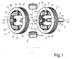
- FIG. 1 a prior art field generator is shown. Since the prior art field generator contains similar elements and generates a similar electric and magnetic field the prior art field generator will be described in detail.
- FIG. 1 there is shown a schematic side view of a prior art treatment apparatus. The parts included are two ringshaped solenoid systems 2 coaxially arranged horizontally and at some distance from one another. Each solenoid system 2 is at its circumference equipped with a solenoid 3. These solenoids are electrically connected in series and form together a magnetic field generator system 4. Between the two solenoid systems 2 there is a lower and an upper field electrode 5,6 arranged in a way, that the central axis in each field electrode coincide with each other.
- the common central axis of the field electrodes 5,6 intersects the central axis of the solenoid system 2 perpendicular and at essentially the same distance from each solenoid system 2.
- the solenoid systems 2 and the field electrodes 5,6 are arranged in a way that each of them can manually be adjusted along a horizontal resp. vertical direction with respect to each other. This arrangement results in that the centre of the treatment apparatus i.e. the treatment zone between the solenoid system 2 and the field electrodes 5,6, which is defined by the region where the magnetic and electric fields cross, can be adjusted to larger or smaller size and in this way be adapted to the size of the object to be treated, for example it cam be smaller if an object such as an ankle is to be treated, or larger when a femur is to be treated.
- Each of the solenoid systems 2 included in the treatment apparatus consists of a ringshaped core 7, built up of transformer core sheets 8. These sheet metal lamina of for example iron, are in a conventional way isolated from each other and tightly packed in the longitudinal axial direction of the solenoid system 2.
- In the defined inner space of each ringshaped core 7 is arranged one magnetic and one electric lens 9,10.
- the elements 12- 15, 19 - 22 included in each lens are attached to the inner surface of the ringshaped core 7.
- the solenoid 3 consists of an isolated copper coiling whose wire diameter is adjusted to the maximum current which is to be fed through the solenoid 3.
- two side plates 24 of dielectric material are arranged at each side surfaces of the solenoids. In order to maintain a sufficient strong magnetic field a number of wiring turns may be necessary.
- Both of the solenoids 3 included in the treatment apparatus are electrically connected in series whereby a homogenous magnetic field is maintained in the treatment zone.
- the magnetic lens 9 arranged in the core 7 is of the so called quadrupole type and contains four lens elements 12 - 15 each of which forms a magnetic pole.
- the preferably cylindrically shaped lens elements 12 - 15, which for example can be punched out from the same material as the ringshaped core 7 are located symmetrically along the inner surface of the core 7 in such a way that the two lens elements 12, 13 which forms the north poles and the two lens elements 14, 15 which forms south poles are arrange in pairs opposite each other.
- the surface of the lens element 12 - 15 turned inwardly towards the centre of the magnetic lens 9 are hyperbolically formed. Hereby a more homogenous magnetic field in the centre of the magnetic lens is maintained.
- Around each lens element 12 - 15 there are arranged lens solenoids 16 in such a manner that the central axis of each solenoid 16 coincides within one and the same point in the centre of the solenoid system 2.
- the lens solenoids 16 are connected electrically in a way that two diametrically arranged lens elements 14,15 work as south poles and the other two as north poles.
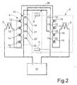
- the lens solenoids 16 included in the magnetic lens can be electrically connected in series and connected to a voltage unit 17.
- the main purpose of the magnetic lens 9 is to converge electrically charged particles which pass through the magnetic lens 9. Its function should, however, be seen in relation to other included parts of the electromagnetic treatment apparatus 1.
- the electric lens 10 included in the solenoid system 2 is of the so called quadrupole type, i.e. also this has four lens elements here called lens electrodes 19 - 22,
- Each lens electrode 19 - 22 consists of an electrically conducting material, for example copper or the like, and is essentially rod shaped.
- the surface facing the centre of the solenoid system is preferably hyperbolically shaped in order to maintain the desired field distribution.
- the lens electrodes 19 - 22 are symmetrically arranged inside the ringshaped core 7 of the solenoid systems 2, in such a way that the two lens electrodes 19,20 with positive potential and the two lens electrodes 21, 22 with negative potential are arranged in pairs diametrically opposite to each other.
- the lens electrodes 19 - 22 that are electrically insulated from the ringshaped core with insulators 25 are displaced by an angle of 45° relative to the lens elements 12 - 15 contained in the solenoid system 2.
- the lens electrodes 21 - 22 that have a negative potential is connected and wired to the negative terminal of the voltage unit 17.
- the above described electrical lens 10 diverges the electrically charged particles that pass through its central section.
- an electric field which is directed perpendicular to the magnetic field.
- This electrical field is generated by an upper and a lower field electrode 6,5 constituting part of an electrical field generator 26.
- the upper field electrode 6 consists of a ringshaped pipe of metal whereon the pipe end turned towards the treatment zone is hyperbolically shaped. This upper field electrode 6 is supplied with a positive potential, which results in that the flow of the electrical filed is directed downwards.
- the lower field electrode 5 consists in the same way as the upper field electrode of metal and is formed as a ringshaped pipe.
- a grid 23 is arranged at its inner edge.
- the grid 23 consists of bands or rods of tungsten or molybdenium and are arranged in the upper part of the lower field electrode 5.
- the upper edges of the grid 23 are formed with a sharp egg-shaped profile and directed towards the upper field electrode 6.
- an electric field is obtained, whose flow is focussed toward the.inner part of the lower field electrode. This results in that a more concentrated field distribution is obtained in the treatment zone.
- all solenoids 16 arranged at the lens elements 12 - 15 are connected in series and all lens electrodes 19, 20 with positive potential are connected together and wired to the positive terminal of the voltage unit 17.
- the lens electrodes 21, 22 are in a related way connected to the negative terminal of the voltage unit 17.
- One and the same voltage unit supply the entire treatment apparatus 1 with is electrical energy.
- the voltage consists of a half wave-rectified sinus voltage that never passes zero.
- the frequency with which the voltage varies has been chosen to 66 Hz, but can naturally vary between for example 20 and 100 Hz. Also the amplitude of the voltage is freely adjustable.
- the voltage to the solenoids 3 and 16 can either be positive or negative.
- a pipe or a nozzle 27 for gas or liquid additive can be arranged at one or both ends of the electromagnetic apparatus, i.e. coaxially with the central axis of solenoid system 2.
- electrically charged particles possibly mixed with one or more medically active substances can be supplied to the treatment zone via the solenoid systems.
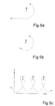
- Fig. 5a - 5c shows paths of charged particles in different fields according to accepted laws of nature.
- E and B represent an electric and a magnetic field.
- fig 5a is shown the movement path of a positive particle in a magnetic field directed "away from the viewer”.
- fig. 5b is shown the movement path of a negative particle in a magnetic field directed "toward the viewer”.
- fig 5c is shown how a negatively charged particle performs a helically shaped movement in two against each other perpendicular fields, whereby the particle is transported over a distance W.
- a magnetic field B directed toward the viewer and an electric field E directed upward (as shown by arrows). It is among other things this movement that is achieved by electromagnetic treatment apparatus described in EP 062032 and electromagnetic treatment apparatus according to the invention.
- an ion is a particle whose resultant charge is either positive or negative, it is influenced by electric and magnetic fields. If the ion passes through one of these fields energy is transferred to it whereby it moves along paths as shown in fig 5a -5c. The velocity of the ion depends among other factors on the viscosity of the surrounding substance. Also the ability of the ion to drag with it other particles in the substance can effect the mobility. Convection movements in the substance and density gradients can to some extent also affect the movement of the ion.
- An electromedical treatment apparatus according to the invention or EP 062032 is effective also on deeper lying tissue. This is due to that all positive or negative charged particles in an electric or magnetic field are affected and that these particles are spread in all parts of the tissue.
- the electromagnetic radiation is intended to affect the bioelectrical potentials on the cellular plane of the organism. Cell membranes and mitochondria etc. but naturally also will affect water distribution in the organism depending on the specific structure of the water molecules. Other organic molecules with dipole characteristic will probably also be affected.
- the treatment apparatus When voltage is supplied the treatment apparatus generates a horizontal magnetic field and a vertical electric field defined by the region where the magnetic and electric fields cross. If charges particles, for example the ions in the blood plasma, are supplied into the treatment zone they are influenced to move in a determined pattern.
- the path of the ions is influenced by the strength of the magnetic and electric fields. They drag with them uncharged particles in their immediate surroundings.
- the strength of the fields is by choice adjustable.
- the magnetic flux density reaches for example 2000 Gauss. Both the strength of the magnetic and electric fields can vary at the rate of the pulse frequency of the introduced voltage.
- a pulse frequency of 66 Hz has been shown to coincide with the biological activity of the body but can, when needed, be adjusted between 20 - 80 Hz.
- the ions By locating the relevant bodypart, for example an arm or leg, in the treatment zone substantially perpendicular to both the magnetic and the electric field, the ions perform a helically formed movement in the direction of the length of the blood vessels (see fig 5c).
- the relevant bodypart for example an arm or leg
- the ions perform a helically formed movement in the direction of the length of the blood vessels (see fig 5c).
- a positively charged particle that approaches a magnetic field will curve and rotate counter clockwise seen in a view of the direction of the flow of the magnetic field. If an electric field is applied perpendicular to the magnetic field and the electric field is directed upward, the positively charged particles will accelerate onto the right side of the magnetic field. If the particle is negatively charged, the relationship will be the opposite.
- the final movement path will be helixshaped, i.e. screwformed, with a constant pitch. This is visualised in fig. 5c.
- an advantageous increase of the blood through flow is obtained in the treated tissue.
- an analgesic i.e. pain reducing, effect can be shown. Pain depends on lack of oxygen in the tissue or on an accumulation of pain substances. An increase of the blood flow gives increased oxygen supply and supports the removal of the pain substances.
- central nervous system works by means of electrically charged particles which among others pass in an out of the nerve cells an in this way transmit information, to for example muscles, also neurologically caused wounds or diseases can be treated with the electromagnetic apparatus described herein.
- leg wounds, burns and slowhealing, infected sores can also be accelerated with the electromagnetic apparatus described herein.
- This can for example be carried out by the fact that a medically active substance such as active iodine, or antibiotics in the form of a spray is supplied to the treatment zone by acceleration from one or both of the solenoid systems 2 via for example a nozzle 27.
- a medically active substance such as active iodine, or antibiotics in the form of a spray
- a bombardment of the wound with medically active substances can thereby be achieved. Due to this method of treatment otherwise developing resistant infection causes can be avoided.
- Fig. 3 shows an exploded view of a field generator for an electromedical treatment apparatus according to the invention
- Fig. 4 which show a top view of a field generator according to the invention
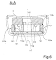
- Fig. 6 which show a cross section of a field generator according to the invention along the section A - A in fig 4 and Fig.7, which show a view from below of a support element for the magnetic lenses, the main core and the main coil.
- the field generator according to the invention can preferably be used in an electromedical treatment apparatus of the prior art type described in relation to figure 1.
- the field generator includes a magnetic field generator and an electric field generator.
- the magnetic field generator includes at least one solenoid 3 arranged on a main core 7 defining an opening 111.
- the main core 7 has first and second axial wall portions 112a, 112b wherein said opening 111 is defined and inner and outer radial wall portions 113a, 113b.
- the main core 7 preferably defines a closed magnetic circuit and is in a preferred embodiment arranged as ring- or toroid shaped core.
- the solenoid 3 is arranged on one of said axial wall portions 112a, 112b and preferably partly covering the opening 111 in the main core 7.
- the solenoid 3 would constitute support for magnetic lens elements 114a -d arranged inside an opening or channel 111 in the main core 7 defined by said openings 111 and the inner radial wall 113a of the main core 7.
- the magnetic field generator includes a magnetic lens system.
- the lens system preferably includes an even number of lens elements 114a - d arranged inside said opening or channel of said main core.
- Each magnetic lens 114 a - d includes a lens core element 12 - 15 having two free ends 115 a, 115b, i.e. is not attached to the main core 7 and a solenoid 16 arranged on said lens core element 12 - 15.
- the lens core 12 - 15 is preferably pinshaped, i.e. shaped as a elongated cylindrical element having two end portions 115a, 115b and a envelope surface 116.
- the lens cores 12 - 15 are preferably substantially vertically arranged in relation to the inner wall 113a of the main core 7 and arranged substantially parallel with a plane extending perpendicularly to a central axis of said channel or opening 111 of said main core 7.
- the end portions 115a of the lens cores, directed towards the central axis 117 of the channel or opening of said main core 7, are preferably hyperbolically shaped.
- Each lens core 12 - 15 carries a lens solenoid 16 arranged on the lens cores.
- Each lens solenoid 16 has two free wire connections 118a, 118b each connected to a circuit card 101.
- the circuit card 101 supports the main core 7 as well as the lens solenoids 16.
- the lens cores 12 - 15 are axially moveably arranged within the lens solenoids 16 and can therefore, after the magnetic lens elements 114a - d and the main core 7 has been arranged on the circuit card 101, slide towards the main core 7 whereby the lens cores 12 -15 make contact with the main core 7.
- the magnetic lens elements 114a - d are supported by a support element 102 arranged inside the channel or opening 111 of the main core 7.
- the support element 102 is made of a nonmagnetic and non-conducting material, for example of a plastic material.
- the support element 102 has a first set 119 of support surfaces arranged for preventing movement of the main core in a radial direction furthermore the support element has a second set 120 of support surfaces arranged for preventing dislocation of the magnetic lens elements and in particular for preventing dislocation of the lens cores slidably arranged in the lens solenoids.
- the support element in a preferred embodiment includes a third set 121 of support surfaces arranged for supporting a circuit card and in a still further preferred embodiment a fourth set 122 of support surfaces arranged for supporting the main solenoid.
- the support element 102 is substantially shaped as a cylinder having recesses forming 123 said second set 120 of support surfaces.
- the radially outwardly directed envelope surface constitutes said first set 119 of supporting surfaces and parts of a first and a second axial end walls constitutes said third and fourth set 119, 120 of supporting surfaces.
- an axial cross section of the support element 102 is of the shape of a Maltese cross, where the gaps between the wings of the cross constitutes support for the lens elements and the radially outwardly directed parts of the wings constitutes support for preventing dislocation of the main core.
- the end wall 121 constituting support for a circuit card 101 is in a preferred embodiment provided with attachment means 103, 104 for attaching to the circuit card.
- the attachment means 103, 104 are in form of a set of knobs adapted for a snug fit in holes 124a, 124b arranged on the circuit card.
- the support element 102 could be arranged as a solid body or, as shown in fig 3, encompass cavities 125.
- the cavities 125 could be open or closed.
- the support element 102 includes distribution channels 126 for facilitating access for injection of a solidifying compound. The compound is injected after assembling the field generator for stabilising the generator and preventing dislocation of any of its parts.
- the distribution channels 126 are formed as recesses provided in the second set 120 of support surfaces giving support to the lens elements.
- the fourth set 122 of supporting surfaces includes in a preferred embodiment means 127 for preventing radial dislocation of the main coil 3. In the embodiment shown in fig. 3 these means 127 are formed as an axial protrusion on the fourth set 122 of supporting surfaces of the support element.
- the protrusion 127 is preferably formed for a snug fit in a central opening 128 of a toroid shaped main solenoid 3.
- the support element 102 thereby gives axial and radial support for the main solenoid 3.
- the support element 102 could be provided with a narrow connection channel 106 for an end wire 129 of the main solenoid.
- the connection channel retains the wire and therefore even further stabilises the field generator and facilitates connection for the free end to the circuit card.
- the other free wire end 130 of the main solenoid is preferably connected to the same circuit card 101, preferably in a connection radially outside the main core.
- the circuit card 101 which is of conventional type, includes connections 131a,b for the free wire ends of the lens solenoids.
- the circuit card further includes connection 17 for voltage supply to the lens solenoids and preferably also for the main solenoid.
- the circuit card also includes electrical conductors (not shown), formed by etching according to normal practice, connecting opposite pairs of magnetic south poles and opposite pairs of magnetic north poles.
- the magnetic lens elements preferably constitute a quadrupol element having two diametrically opposed south poles and two diametrically opposed south poles. The southpoles are arranged at 90° from each other.
- the circuit card furthermore, in a preferred embodiment includes an even number of electrical lens elements 19 - 22, preferably four, forming part of an electric lens system in an electric field generator.
- the lens elements 19 - 22 are arranged radially within the opening of the main core.
- the electrical lens elements are formed as plate shaped electrodes arranged on or in the circuit card.
- the electrical lens elements are preferably hyperbolically shaped in the region 132 directed towards the centre of the opening of the main core.
- the circuit card furthermore includes conductors connecting the electrical lens elements in pairs of positive potential and pairs of negative potential where each electrode in a pair is arranged at substantially diametrically opposed positions.
- the electrical lens system is of quadrupol type and includes four lens elements, two intended to have negative potential arranged at diametrically opposite positions and two lens elements intended to have positive potential arranged at diametrically opposite positions, where the negative and the positive electrodes are arranged 90° from each other.
- the electrical lenses are arranged at 45° from the positions of the magnetic lenses.
- the circuit card is provided with attachment means for attaching the circuit card to a housing.
- the attachment means are formed as knobs arranged on the inside of the housing which are arranged for being received in holes arranged on the circuit card.
- the invention also relates to a method of producing a field generator for an electromedical treatment apparatus for treatment of biological tissue.
- the method involves a series of method steps.
- the magnetic lenses, the support element and the main core is attached to a circuit card.
- free ends of solenoids of the magnetic lens elements are attached to connections provided at the circuit card.
- the support element is attached to the circuit card thereby immediately stabilising the lens elements.
- the main core is assembled by positioning the main core around the support element. By that operation the lens core elements positioned inside the lens solenoids are prevented from being dislocated.
- the main solenoid is arranged on the main core.
- the main solenoid at least partly covers the opening in the main core and thereby together with the main core, the support element and the circuit card encloses the lens solenoids.
- the circuit card is thereafter attached to an inside wall of a housing by attachment means.
- a solidifying compound is injected into the housing after the assembly of the parts of the field generator has been completed thereby still further stabilising the parts of the field generator from being dislocated. Epoxy could be used as solidifying compound.
Landscapes
- Health & Medical Sciences (AREA)
- Engineering & Computer Science (AREA)
- Biomedical Technology (AREA)
- Nuclear Medicine, Radiotherapy & Molecular Imaging (AREA)
- Radiology & Medical Imaging (AREA)
- Life Sciences & Earth Sciences (AREA)
- Animal Behavior & Ethology (AREA)
- General Health & Medical Sciences (AREA)
- Public Health (AREA)
- Veterinary Medicine (AREA)
- Magnetic Treatment Devices (AREA)
- Plasma Technology (AREA)
- Drying Of Semiconductors (AREA)
Priority Applications (2)
| Application Number | Priority Date | Filing Date | Title |
|---|---|---|---|
| PCT/EP2001/007559 WO2002004072A1 (fr) | 2000-07-07 | 2001-07-02 | Generateur de champ magnetique utilise dans un appareil de traitement electromedical |
| AU2001281938A AU2001281938A1 (en) | 2000-07-07 | 2001-07-02 | Magnetic generator for an electromedical treatment apparatus |
Applications Claiming Priority (2)
| Application Number | Priority Date | Filing Date | Title |
|---|---|---|---|
| SE0002568 | 2000-07-07 | ||
| SE0002568A SE517159C2 (sv) | 2000-07-07 | 2000-07-07 | Magnetfältgenerator för en elektromedicinsk behandlingsapparat samt förfarande för framställning därav |
Publications (2)
| Publication Number | Publication Date |
|---|---|
| EP1170032A1 true EP1170032A1 (fr) | 2002-01-09 |
| EP1170032B1 EP1170032B1 (fr) | 2004-10-27 |
Family
ID=20280408
Family Applications (1)
| Application Number | Title | Priority Date | Filing Date |
|---|---|---|---|
| EP20000850144 Expired - Lifetime EP1170032B1 (fr) | 2000-07-07 | 2000-08-28 | Générateur de champ magnétique pour un apparaeil de traitement électromédical |
Country Status (5)
| Country | Link |
|---|---|
| EP (1) | EP1170032B1 (fr) |
| AT (1) | ATE280618T1 (fr) |
| DE (1) | DE60015316T2 (fr) |
| SE (1) | SE517159C2 (fr) |
| TW (1) | TW526072B (fr) |
Cited By (1)
| Publication number | Priority date | Publication date | Assignee | Title |
|---|---|---|---|---|
| WO2017036585A1 (fr) * | 2015-08-28 | 2017-03-09 | Peter Feucht | Générateur de champ magnétique en tant que simulateur de champ naturel |
Families Citing this family (1)
| Publication number | Priority date | Publication date | Assignee | Title |
|---|---|---|---|---|
| US9881711B2 (en) * | 2014-09-12 | 2018-01-30 | Mitsubishi Electric Corporation | Beam transport system and particle beam therapy system |
Citations (5)
| Publication number | Priority date | Publication date | Assignee | Title |
|---|---|---|---|---|
| GB871672A (en) | 1958-10-28 | 1961-06-28 | Nemec Hans | Apparatus for medical purposes |
| US3915151A (en) | 1973-03-23 | 1975-10-28 | Werner Kraus | Apparatus for promoting healing processes |
| EP0062032A1 (fr) | 1980-10-03 | 1982-10-13 | Henning Rosengart | Appareil de traitement electro-medical. |
| EP0383457A1 (fr) * | 1989-01-31 | 1990-08-22 | Kanazawa University | Générateur de champ magnétique alternatif interne à économie de puissance du type à couches multiples et à courants de Foucault |
| EP0453602A1 (fr) * | 1990-04-26 | 1991-10-30 | Nihonkenkozoshinkenkyukai Co. Ltd. | Appareil thÀ©rapeutique générant des champs magnétiques |
-
2000
- 2000-07-07 SE SE0002568A patent/SE517159C2/sv not_active IP Right Cessation
- 2000-08-28 AT AT00850144T patent/ATE280618T1/de not_active IP Right Cessation
- 2000-08-28 DE DE60015316T patent/DE60015316T2/de not_active Expired - Fee Related
- 2000-08-28 EP EP20000850144 patent/EP1170032B1/fr not_active Expired - Lifetime
-
2002
- 2002-01-04 TW TW091100052A patent/TW526072B/zh not_active IP Right Cessation
Patent Citations (5)
| Publication number | Priority date | Publication date | Assignee | Title |
|---|---|---|---|---|
| GB871672A (en) | 1958-10-28 | 1961-06-28 | Nemec Hans | Apparatus for medical purposes |
| US3915151A (en) | 1973-03-23 | 1975-10-28 | Werner Kraus | Apparatus for promoting healing processes |
| EP0062032A1 (fr) | 1980-10-03 | 1982-10-13 | Henning Rosengart | Appareil de traitement electro-medical. |
| EP0383457A1 (fr) * | 1989-01-31 | 1990-08-22 | Kanazawa University | Générateur de champ magnétique alternatif interne à économie de puissance du type à couches multiples et à courants de Foucault |
| EP0453602A1 (fr) * | 1990-04-26 | 1991-10-30 | Nihonkenkozoshinkenkyukai Co. Ltd. | Appareil thÀ©rapeutique générant des champs magnétiques |
Cited By (1)
| Publication number | Priority date | Publication date | Assignee | Title |
|---|---|---|---|---|
| WO2017036585A1 (fr) * | 2015-08-28 | 2017-03-09 | Peter Feucht | Générateur de champ magnétique en tant que simulateur de champ naturel |
Also Published As
| Publication number | Publication date |
|---|---|
| ATE280618T1 (de) | 2004-11-15 |
| SE517159C2 (sv) | 2002-04-23 |
| SE0002568D0 (sv) | 2000-07-07 |
| DE60015316D1 (de) | 2004-12-02 |
| TW526072B (en) | 2003-04-01 |
| EP1170032B1 (fr) | 2004-10-27 |
| DE60015316T2 (de) | 2005-11-03 |
| SE0002568L (sv) | 2002-01-08 |
Similar Documents
| Publication | Publication Date | Title |
|---|---|---|
| EP0062032B1 (fr) | Appareil de traitement electro-medical | |
| AU2016203613B2 (en) | Sequentially programmed magnetic therapeutic system (SPMF) | |
| EP0338681B1 (fr) | Appareil pour appliquer un champ magnétique à un tissu | |
| US10170281B2 (en) | System and method for plasma treatment using directional dielectric barrier discharge energy system | |
| JPS6141583B2 (fr) | ||
| WO2001007111A2 (fr) | Toroides magnetiques pour la stimulation du tissu biologique | |
| DE3825165A1 (de) | Diathermiegeraet | |
| KR100950795B1 (ko) | 전자기장 중복 출력 치료기 | |
| EP1170032B1 (fr) | Générateur de champ magnétique pour un apparaeil de traitement électromédical | |
| WO2002004072A1 (fr) | Generateur de champ magnetique utilise dans un appareil de traitement electromedical | |
| DE3417773A1 (de) | Vorrichtung zur herstellung pulsierender magnetfelder fuer therapeutische zwecke | |
| Gupta et al. | Comparative study of bone growth by pulsed electromagnetic fields | |
| CN113546323A (zh) | 治疗用磁环阵列装置 | |
| Downes et al. | Development of the iron-cored electromagnet for the treatment of non-union and delayed union | |
| RU2229907C2 (ru) | Способ лечения закрытой черепно-мозговой травмы и устройство для его осуществления | |
| CN215309728U (zh) | 磁环阵列治疗设备 | |
| RU2066213C1 (ru) | Биогальваномассажное устройство | |
| SU1342513A1 (ru) | Устройство дл стимул ции репаративного остеогенеза | |
| RU2262359C2 (ru) | Устройство для селективной магнитотерапии | |
| SE416269B (sv) | Elektromedicinsk behandlingsanordning | |
| RU2074749C1 (ru) | Магнитотерапевтическая установка | |
| WO2008103070A2 (fr) | Procédé de traitement électrostimulant de flux et cohérent et dispositif de réalisation correspondant | |
| CN1106869C (zh) | 疑难病全息康复治疗装置 | |
| Lunt | A broader spectrum of therapy | |
| KR20210117994A (ko) | 복부 및 두상부 운동치료 전자기 출력기 |
Legal Events
| Date | Code | Title | Description |
|---|---|---|---|
| PUAI | Public reference made under article 153(3) epc to a published international application that has entered the european phase |
Free format text: ORIGINAL CODE: 0009012 |
|
| AK | Designated contracting states |
Kind code of ref document: A1 Designated state(s): AT BE CH CY DE DK ES FI FR GB GR IE IT LI LU MC NL PT SE |
|
| AX | Request for extension of the european patent |
Free format text: AL;LT;LV;MK;RO;SI |
|
| 17P | Request for examination filed |
Effective date: 20020703 |
|
| AKX | Designation fees paid |
Free format text: AT BE CH CY DE DK ES FI FR GB GR IE IT LI LU MC NL PT SE |
|
| GRAP | Despatch of communication of intention to grant a patent |
Free format text: ORIGINAL CODE: EPIDOSNIGR1 |
|
| GRAS | Grant fee paid |
Free format text: ORIGINAL CODE: EPIDOSNIGR3 |
|
| GRAA | (expected) grant |
Free format text: ORIGINAL CODE: 0009210 |
|
| AK | Designated contracting states |
Kind code of ref document: B1 Designated state(s): AT BE CH CY DE DK ES FI FR GB GR IE IT LI LU MC NL PT SE |
|
| PG25 | Lapsed in a contracting state [announced via postgrant information from national office to epo] |
Ref country code: IT Free format text: LAPSE BECAUSE OF FAILURE TO SUBMIT A TRANSLATION OF THE DESCRIPTION OR TO PAY THE FEE WITHIN THE PRESCRIBED TIME-LIMIT;WARNING: LAPSES OF ITALIAN PATENTS WITH EFFECTIVE DATE BEFORE 2007 MAY HAVE OCCURRED AT ANY TIME BEFORE 2007. THE CORRECT EFFECTIVE DATE MAY BE DIFFERENT FROM THE ONE RECORDED. Effective date: 20041027 Ref country code: FI Free format text: LAPSE BECAUSE OF FAILURE TO SUBMIT A TRANSLATION OF THE DESCRIPTION OR TO PAY THE FEE WITHIN THE PRESCRIBED TIME-LIMIT Effective date: 20041027 Ref country code: NL Free format text: LAPSE BECAUSE OF FAILURE TO SUBMIT A TRANSLATION OF THE DESCRIPTION OR TO PAY THE FEE WITHIN THE PRESCRIBED TIME-LIMIT Effective date: 20041027 |
|
| REG | Reference to a national code |
Ref country code: GB Ref legal event code: FG4D |
|
| REG | Reference to a national code |
Ref country code: CH Ref legal event code: EP |
|
| REG | Reference to a national code |
Ref country code: IE Ref legal event code: FG4D |
|
| REF | Corresponds to: |
Ref document number: 60015316 Country of ref document: DE Date of ref document: 20041202 Kind code of ref document: P |
|
| PG25 | Lapsed in a contracting state [announced via postgrant information from national office to epo] |
Ref country code: DK Free format text: LAPSE BECAUSE OF FAILURE TO SUBMIT A TRANSLATION OF THE DESCRIPTION OR TO PAY THE FEE WITHIN THE PRESCRIBED TIME-LIMIT Effective date: 20050127 Ref country code: GR Free format text: LAPSE BECAUSE OF FAILURE TO SUBMIT A TRANSLATION OF THE DESCRIPTION OR TO PAY THE FEE WITHIN THE PRESCRIBED TIME-LIMIT Effective date: 20050127 Ref country code: SE Free format text: LAPSE BECAUSE OF FAILURE TO SUBMIT A TRANSLATION OF THE DESCRIPTION OR TO PAY THE FEE WITHIN THE PRESCRIBED TIME-LIMIT Effective date: 20050127 |
|
| REG | Reference to a national code |
Ref country code: CH Ref legal event code: NV Representative=s name: E. BLUM & CO. PATENTANWAELTE |
|
| PG25 | Lapsed in a contracting state [announced via postgrant information from national office to epo] |
Ref country code: ES Free format text: LAPSE BECAUSE OF FAILURE TO SUBMIT A TRANSLATION OF THE DESCRIPTION OR TO PAY THE FEE WITHIN THE PRESCRIBED TIME-LIMIT Effective date: 20050327 |
|
| NLV1 | Nl: lapsed or annulled due to failure to fulfill the requirements of art. 29p and 29m of the patents act | ||
| PGFP | Annual fee paid to national office [announced via postgrant information from national office to epo] |
Ref country code: FR Payment date: 20050826 Year of fee payment: 6 |
|
| PG25 | Lapsed in a contracting state [announced via postgrant information from national office to epo] |
Ref country code: CY Free format text: LAPSE BECAUSE OF FAILURE TO SUBMIT A TRANSLATION OF THE DESCRIPTION OR TO PAY THE FEE WITHIN THE PRESCRIBED TIME-LIMIT Effective date: 20050828 |
|
| PLBE | No opposition filed within time limit |
Free format text: ORIGINAL CODE: 0009261 |
|
| STAA | Information on the status of an ep patent application or granted ep patent |
Free format text: STATUS: NO OPPOSITION FILED WITHIN TIME LIMIT |
|
| 26N | No opposition filed |
Effective date: 20050728 |
|
| ET | Fr: translation filed | ||
| PGFP | Annual fee paid to national office [announced via postgrant information from national office to epo] |
Ref country code: IE Payment date: 20060801 Year of fee payment: 7 Ref country code: BE Payment date: 20060801 Year of fee payment: 7 Ref country code: CH Payment date: 20060801 Year of fee payment: 7 |
|
| PGFP | Annual fee paid to national office [announced via postgrant information from national office to epo] |
Ref country code: AT Payment date: 20060803 Year of fee payment: 7 |
|
| PGFP | Annual fee paid to national office [announced via postgrant information from national office to epo] |
Ref country code: LU Payment date: 20060809 Year of fee payment: 7 |
|
| PGFP | Annual fee paid to national office [announced via postgrant information from national office to epo] |
Ref country code: MC Payment date: 20060811 Year of fee payment: 7 |
|
| PGFP | Annual fee paid to national office [announced via postgrant information from national office to epo] |
Ref country code: GB Payment date: 20060830 Year of fee payment: 7 Ref country code: DE Payment date: 20060830 Year of fee payment: 7 |
|
| REG | Reference to a national code |
Ref country code: CH Ref legal event code: PFA Owner name: MED-TECH A/S Free format text: MED-TECH A/S#NOERREBRO 3#9881 BINDSLEV (DK) -TRANSFER TO- MED-TECH A/S#NOERREBRO 3#9881 BINDSLEV (DK) |
|
| PG25 | Lapsed in a contracting state [announced via postgrant information from national office to epo] |
Ref country code: PT Free format text: LAPSE BECAUSE OF NON-PAYMENT OF DUE FEES Effective date: 20050327 |
|
| BERE | Be: lapsed |
Owner name: *MED-TECH A/S Effective date: 20070831 |
|
| REG | Reference to a national code |
Ref country code: CH Ref legal event code: PL |
|
| GBPC | Gb: european patent ceased through non-payment of renewal fee |
Effective date: 20070828 |
|
| PG25 | Lapsed in a contracting state [announced via postgrant information from national office to epo] |
Ref country code: LI Free format text: LAPSE BECAUSE OF NON-PAYMENT OF DUE FEES Effective date: 20070831 Ref country code: CH Free format text: LAPSE BECAUSE OF NON-PAYMENT OF DUE FEES Effective date: 20070831 Ref country code: MC Free format text: LAPSE BECAUSE OF NON-PAYMENT OF DUE FEES Effective date: 20070831 |
|
| REG | Reference to a national code |
Ref country code: IE Ref legal event code: MM4A |
|
| PG25 | Lapsed in a contracting state [announced via postgrant information from national office to epo] |
Ref country code: AT Free format text: LAPSE BECAUSE OF NON-PAYMENT OF DUE FEES Effective date: 20070828 |
|
| REG | Reference to a national code |
Ref country code: FR Ref legal event code: ST Effective date: 20080430 |
|
| PG25 | Lapsed in a contracting state [announced via postgrant information from national office to epo] |
Ref country code: DE Free format text: LAPSE BECAUSE OF NON-PAYMENT OF DUE FEES Effective date: 20080301 |
|
| PG25 | Lapsed in a contracting state [announced via postgrant information from national office to epo] |
Ref country code: BE Free format text: LAPSE BECAUSE OF NON-PAYMENT OF DUE FEES Effective date: 20070831 |
|
| PG25 | Lapsed in a contracting state [announced via postgrant information from national office to epo] |
Ref country code: IE Free format text: LAPSE BECAUSE OF NON-PAYMENT OF DUE FEES Effective date: 20070828 Ref country code: FR Free format text: LAPSE BECAUSE OF NON-PAYMENT OF DUE FEES Effective date: 20070831 |
|
| PG25 | Lapsed in a contracting state [announced via postgrant information from national office to epo] |
Ref country code: GB Free format text: LAPSE BECAUSE OF NON-PAYMENT OF DUE FEES Effective date: 20070828 |
|
| PG25 | Lapsed in a contracting state [announced via postgrant information from national office to epo] |
Ref country code: FR Free format text: LAPSE BECAUSE OF NON-PAYMENT OF DUE FEES Effective date: 20060831 |
|
| PG25 | Lapsed in a contracting state [announced via postgrant information from national office to epo] |
Ref country code: LU Free format text: LAPSE BECAUSE OF NON-PAYMENT OF DUE FEES Effective date: 20070828 |