EP1170099A2 - Outil de poinçonnage pour produire des ouvertures dans une pièce en matériau thermoplastique - Google Patents
Outil de poinçonnage pour produire des ouvertures dans une pièce en matériau thermoplastique Download PDFInfo
- Publication number
- EP1170099A2 EP1170099A2 EP01108679A EP01108679A EP1170099A2 EP 1170099 A2 EP1170099 A2 EP 1170099A2 EP 01108679 A EP01108679 A EP 01108679A EP 01108679 A EP01108679 A EP 01108679A EP 1170099 A2 EP1170099 A2 EP 1170099A2
- Authority
- EP
- European Patent Office
- Prior art keywords
- cutting edge
- cutting
- shaped
- workpiece
- punch
- Prior art date
- Legal status (The legal status is an assumption and is not a legal conclusion. Google has not performed a legal analysis and makes no representation as to the accuracy of the status listed.)
- Withdrawn
Links
- 238000005520 cutting process Methods 0.000 title claims abstract description 64
- 239000012815 thermoplastic material Substances 0.000 title claims description 3
- 230000007704 transition Effects 0.000 claims abstract description 7
- 238000004080 punching Methods 0.000 claims description 20
- 239000000463 material Substances 0.000 claims description 9
- 230000000149 penetrating effect Effects 0.000 claims description 2
- 238000010438 heat treatment Methods 0.000 description 8
- 238000000034 method Methods 0.000 description 5
- 229920001169 thermoplastic Polymers 0.000 description 5
- 239000004416 thermosoftening plastic Substances 0.000 description 5
- 238000009499 grossing Methods 0.000 description 3
- 238000007731 hot pressing Methods 0.000 description 3
- 230000015572 biosynthetic process Effects 0.000 description 2
- 238000004519 manufacturing process Methods 0.000 description 2
- 239000003973 paint Substances 0.000 description 2
- 238000007493 shaping process Methods 0.000 description 2
- 238000003856 thermoforming Methods 0.000 description 2
- 238000009825 accumulation Methods 0.000 description 1
- 238000006073 displacement reaction Methods 0.000 description 1
- 230000003993 interaction Effects 0.000 description 1
- 230000003287 optical effect Effects 0.000 description 1
- 238000010422 painting Methods 0.000 description 1
Images


Classifications
-
- B—PERFORMING OPERATIONS; TRANSPORTING
- B26—HAND CUTTING TOOLS; CUTTING; SEVERING
- B26F—PERFORATING; PUNCHING; CUTTING-OUT; STAMPING-OUT; SEVERING BY MEANS OTHER THAN CUTTING
- B26F1/00—Perforating; Punching; Cutting-out; Stamping-out; Apparatus therefor
- B26F1/38—Cutting-out; Stamping-out
- B26F1/44—Cutters therefor; Dies therefor
-
- B—PERFORMING OPERATIONS; TRANSPORTING
- B26—HAND CUTTING TOOLS; CUTTING; SEVERING
- B26D—CUTTING; DETAILS COMMON TO MACHINES FOR PERFORATING, PUNCHING, CUTTING-OUT, STAMPING-OUT OR SEVERING
- B26D7/00—Details of apparatus for cutting, cutting-out, stamping-out, punching, perforating, or severing by means other than cutting
- B26D7/08—Means for treating work or cutting member to facilitate cutting
- B26D7/10—Means for treating work or cutting member to facilitate cutting by heating
-
- B—PERFORMING OPERATIONS; TRANSPORTING
- B26—HAND CUTTING TOOLS; CUTTING; SEVERING
- B26F—PERFORATING; PUNCHING; CUTTING-OUT; STAMPING-OUT; SEVERING BY MEANS OTHER THAN CUTTING
- B26F1/00—Perforating; Punching; Cutting-out; Stamping-out; Apparatus therefor
- B26F1/38—Cutting-out; Stamping-out
- B26F1/40—Cutting-out; Stamping-out using a press, e.g. of the ram type
-
- B—PERFORMING OPERATIONS; TRANSPORTING
- B26—HAND CUTTING TOOLS; CUTTING; SEVERING
- B26F—PERFORATING; PUNCHING; CUTTING-OUT; STAMPING-OUT; SEVERING BY MEANS OTHER THAN CUTTING
- B26F1/00—Perforating; Punching; Cutting-out; Stamping-out; Apparatus therefor
- B26F1/38—Cutting-out; Stamping-out
- B26F1/44—Cutters therefor; Dies therefor
- B26F2001/4472—Cutting edge section features
Definitions
- the invention relates to a punching tool for producing openings in workpieces Made of thermoplastic material with a cutting edge running around the front having, can be brought into engagement with a cutting plate in a working stroke and thereby the workpiece arranged between its cutting edge and the insert Generation of a breakthrough in the cutting direction penetrating locally heatable Punch.
- Openings often have to be made in molded parts made of thermoplastic. When the openings are punched out, the formation of burrs or cracks is disadvantageous felt. Subsequent painting involves the sharp edges Paint accumulation and, as a result, flaking of the paint. This can be a Assume that the aesthetic appearance suffers. A Reworking the cut edges would be an additional step in series production Require labor.
- a 1 describes a cutting tool and a method for punching Workpieces made of thermoplastic, in particular of flat motor vehicle add-on parts known.
- a punch is in a column frame with an insert in a working stroke can be brought into engagement, wherein a wall opening in a workpiece is produced.
- thermoplastic workpiece Another solution for shaping a thermoplastic workpiece using a Punching device is known from DE 197 48 407 A1.
- a punching device on the foot of a punch knife a fillet profile with such a heating device that a predetermined punched edge profile is created by locally hot pressing the workpiece.
- the outer surface of the cylindrical punching knife runs in at the foot of the same a groove-shaped area, the shape of which with respect to the desired Cross-sectional shape of the workpiece is selected at this point.
- thermoplastic is removed by a heating device arranged in the throat area Material of the workpiece locally, i.e. H. heated in the area of the throat so that one for Sufficient softening occurs through shaping by hot pressing.
- the invention is based on the object To provide punching tool, the stamp for both the top and for the Through cut is suitable, with a smooth, burr-free at low manufacturing costs Transition between the cut surface and the adjacent surface is achieved.
- the object is achieved in that the stamp of the punching tool as a one-piece, heatable cutting punch with a cutting edge running around the front a V-shaped cutting edge geometry is formed.
- the angle of the V-shaped cutting edge encircling the end face includes one Range from 5 ° to 20 °.
- the height h of the V-shaped cutting edge in the top cut is in accordance with the thickness of the to be punched out material.
- the outer contour of the V-shaped cutting edge has a radial transition.
- the radius of the transition between the outer contour of the V-shaped cutting edge and the Shank diameter of the stamp is preferably smaller than the wall thickness of the to be punched out material.
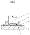
- the punching tool essentially consists of a column frame, a hold-down device (7) for the workpiece (6), a cutting plate (5) and a cutting punch (1) with a Heating device (8).
- FIG. 1 shows a basic illustration of the cutting punch (1) according to the invention.
- This has a V-shaped cutting edge (2) on the end face.
- the outer contour (3) of the V-shaped Cutting edge (2) merges into a radius-shaped area (4).
- the radius of the radius Area (4) is preferably in the area smaller than the wall thickness of the workpiece (6).
- the heating device (8) is arranged in a radial region. Depending on the material of the Workpiece (6), the radius-shaped area is heated to 60 ° C to 130 ° C.
- the height (H) the V-shaped cutting edge (2) is preferably in the area of the top cut Wall thickness of the workpiece (6).
- FIG 2 the process of the top section is shown in principle.
- the cutting punch (1) is moved in an axial stroke in the direction of the cutting plate (5).
- the axial stroke is divided into a working stroke and a return stroke for each cutting process.
- the part of the workpiece (6) punched out during the working stroke is ejected during the return stroke by an ejector arranged in the cutting punch (1).
- the opening is punched out and the radius / smoothing is formed on the visible side of the workpiece (6) through the radius-shaped area (4) of the punch (1) in one operation. Due to the heating of the radius-shaped area (4) by means of the heating device (8), the cut edge of the workpiece (6) is plasticized under contact heating, which is then smoothed according to the contour of the radius-shaped area (4).
- the process is shown in principle when performing a through cut.
- the cutting plate (5) has a conical opening (9) that widens downward from the workpiece support surface.
- the cutting punch (1) is moved in the direction of the cutting plate (5) by an axial stroke.
- the material flows over the edge of the opening (9) in the cutting plate (5).
- the surface is already drawn inwards in a radius.
- the part to be punched out is sheared off by the interaction of the cutting edge (10) of the cutting plate (5) and the outer contour of the V-shaped cutting edge (2).
- the punched-out is ejected over the opening (9).
- the heated radius-shaped area (4) results in a smoothing in the punched area during the lower dead center support of the cutting punch (1).
- the height (H) of the V-shaped cutting edge (2) is greater than the wall thickness of the material to be punched out in the through cut.
- the cutting edge occurs when punching out in a first step after placing the Cutting stamp on the workpiece surface to a process similar to deep drawing.
- the material is already inwards to a certain extent thanks to the V-shaped cutting edge pulled so that a sharp-edged transition to the punching is already avoided. Due to the heated radius-shaped area (4) there is no actual reshaping, but just a smoothing of the surface.
Landscapes
- Life Sciences & Earth Sciences (AREA)
- Forests & Forestry (AREA)
- Engineering & Computer Science (AREA)
- Mechanical Engineering (AREA)
- Physics & Mathematics (AREA)
- Optics & Photonics (AREA)
- Perforating, Stamping-Out Or Severing By Means Other Than Cutting (AREA)
Applications Claiming Priority (2)
| Application Number | Priority Date | Filing Date | Title |
|---|---|---|---|
| DE2000132458 DE10032458A1 (de) | 2000-07-04 | 2000-07-04 | Stanzwerkzeug zur Herstellung von Durchbrüchen in Werkstücken aus thermoplastischem Material |
| DE10032458 | 2000-07-04 |
Publications (2)
| Publication Number | Publication Date |
|---|---|
| EP1170099A2 true EP1170099A2 (fr) | 2002-01-09 |
| EP1170099A3 EP1170099A3 (fr) | 2003-10-15 |
Family
ID=7647740
Family Applications (1)
| Application Number | Title | Priority Date | Filing Date |
|---|---|---|---|
| EP01108679A Withdrawn EP1170099A3 (fr) | 2000-07-04 | 2001-04-06 | Outil de poinçonnage pour produire des ouvertures dans une pièce en matériau thermoplastique |
Country Status (2)
| Country | Link |
|---|---|
| EP (1) | EP1170099A3 (fr) |
| DE (1) | DE10032458A1 (fr) |
Cited By (9)
| Publication number | Priority date | Publication date | Assignee | Title |
|---|---|---|---|---|
| DE10239452A1 (de) * | 2002-08-28 | 2004-03-18 | Dynamit Nobel Kunststoff Gmbh | Prägestanzen von harten Kunststoffen |
| EP1649988A1 (fr) * | 2004-10-22 | 2006-04-26 | G. WACHSMUTH & CO. WERKZEUGBAU GmbH | Dispositif de coupe d'un film, en particulier d'un film multicouche |
| EP1762348A1 (fr) * | 2005-09-12 | 2007-03-14 | Ricoh Company, Ltd. | Dispositif perforateur avec un éffet réduit de déformation a cause de la chaleur et dispositif de formation d'images avec le même |
| DE202008015770U1 (de) | 2008-11-27 | 2009-02-26 | Karl Reichardt, Stanzmesserfabrik Gmbh | Stanzvorrichtung und Heizplatte dafür |
| DE102008059934A1 (de) * | 2008-12-02 | 2010-06-10 | Reiplinger Gmbh & Co. Kg | Stanzstempel und Verwendung des Stanzstempels |
| WO2011128072A1 (fr) * | 2010-04-12 | 2011-10-20 | Faurecia Innenraum Systeme Gmbh | Procédé et dispositif d'outil pour former une couche de mousse d'une pièce moulée |
| DE102010061991A1 (de) * | 2010-11-25 | 2012-05-31 | Bayerische Motoren Werke Aktiengesellschaft | Verfahren zum Stanzen einer aus Fasermaterial bestehenden Fasermatte |
| WO2014111243A3 (fr) * | 2013-01-16 | 2014-09-12 | Rehau Ag + Co | Procédé de production d'un élément structural polymère pour véhicule à moteur |
| CN121244775A (zh) * | 2025-12-04 | 2026-01-02 | 珠海富士智能股份有限公司 | 电池极柱的加工设备及其方法、存储介质 |
Families Citing this family (2)
| Publication number | Priority date | Publication date | Assignee | Title |
|---|---|---|---|---|
| PL1568451T3 (pl) | 2004-02-27 | 2008-06-30 | Nestec Sa | Sposób i urządzenie do wykrawania materiału filtracyjnego |
| CN113211766B (zh) * | 2021-06-15 | 2025-03-14 | 惠州万玺科技有限公司 | 一种热熔性印章垫的压边设备及其印垫压制方法 |
Family Cites Families (9)
| Publication number | Priority date | Publication date | Assignee | Title |
|---|---|---|---|---|
| FR1482554A (fr) * | 1965-06-09 | 1967-05-26 | Procédé d'obtention de lettres, caractères et marques | |
| DE3047886A1 (de) * | 1979-12-20 | 1981-10-29 | The Fujikura Cable Works, Ltd., Tokyo | Verfahren zur herstellung eines stanzwerkzeugs und nach diesem verfahren hergestelltes stanzwerkzeug |
| DE3740435A1 (de) * | 1987-11-28 | 1989-06-15 | Helmut Pelzer | Schneidwerkzeug fuer werkstuecke aus langfaserigen materialien |
| US5622587A (en) * | 1991-12-19 | 1997-04-22 | Barthelman; Kenneth L. | Method for producing a three-dimensional laminated decal composite |
| CN1145050A (zh) * | 1994-04-05 | 1997-03-12 | 美国3M公司 | 切割和密封多孔切边薄片的装置和方法 |
| DE19640562C2 (de) * | 1996-10-01 | 2002-12-19 | Bosch Gmbh Robert | Vorrichtung zum Formen, Füllen, Verschließen und Vereinzeln von Behältern |
| DE19730859A1 (de) * | 1997-07-17 | 1999-01-21 | Magna Pebra Gmbh | Schneidwerkzeug und Verfahren zum Lochen von Werkstücken aus thermoplastischem Kunststoff |
| DE19748407B4 (de) * | 1997-11-03 | 2006-04-06 | Volkswagen Ag | Stanzvorrichtung zur Formgebung eines thermoplastischen Werkstücks |
| DE29720203U1 (de) * | 1997-11-14 | 1998-01-22 | Albert Braach GmbH + Co KG Modell- und Maschinenbau, 57334 Bad Laasphe | Beheiztes Schneidwerkzeug |
-
2000
- 2000-07-04 DE DE2000132458 patent/DE10032458A1/de not_active Withdrawn
-
2001
- 2001-04-06 EP EP01108679A patent/EP1170099A3/fr not_active Withdrawn
Cited By (16)
| Publication number | Priority date | Publication date | Assignee | Title |
|---|---|---|---|---|
| DE10239452A1 (de) * | 2002-08-28 | 2004-03-18 | Dynamit Nobel Kunststoff Gmbh | Prägestanzen von harten Kunststoffen |
| DE10239452B4 (de) * | 2002-08-28 | 2008-02-28 | Plastal Gmbh | Prägestanzen von harten Kunststoffen |
| EP1649988A1 (fr) * | 2004-10-22 | 2006-04-26 | G. WACHSMUTH & CO. WERKZEUGBAU GmbH | Dispositif de coupe d'un film, en particulier d'un film multicouche |
| EP1762348A1 (fr) * | 2005-09-12 | 2007-03-14 | Ricoh Company, Ltd. | Dispositif perforateur avec un éffet réduit de déformation a cause de la chaleur et dispositif de formation d'images avec le même |
| US7762170B2 (en) | 2005-09-12 | 2010-07-27 | Ricoh, Co. Ltd. | Heat-effect reduceable finishing unit and image forming system using the same |
| DE202008015770U1 (de) | 2008-11-27 | 2009-02-26 | Karl Reichardt, Stanzmesserfabrik Gmbh | Stanzvorrichtung und Heizplatte dafür |
| DE102008059934A1 (de) * | 2008-12-02 | 2010-06-10 | Reiplinger Gmbh & Co. Kg | Stanzstempel und Verwendung des Stanzstempels |
| DE102008059934B4 (de) * | 2008-12-02 | 2011-06-16 | Reiplinger Gmbh & Co. Kg | Stanzstempel und Verwendung des Stanzstempels |
| WO2011128072A1 (fr) * | 2010-04-12 | 2011-10-20 | Faurecia Innenraum Systeme Gmbh | Procédé et dispositif d'outil pour former une couche de mousse d'une pièce moulée |
| DE102010061991A1 (de) * | 2010-11-25 | 2012-05-31 | Bayerische Motoren Werke Aktiengesellschaft | Verfahren zum Stanzen einer aus Fasermaterial bestehenden Fasermatte |
| DE102010061991B4 (de) * | 2010-11-25 | 2016-06-09 | Bayerische Motoren Werke Aktiengesellschaft | Verfahren zum Stanzen einer aus Fasermaterial bestehenden Fasermatte |
| WO2014111243A3 (fr) * | 2013-01-16 | 2014-09-12 | Rehau Ag + Co | Procédé de production d'un élément structural polymère pour véhicule à moteur |
| CN104936765A (zh) * | 2013-01-16 | 2015-09-23 | 雷奥两合股份公司 | 聚合物的机动车部件的制造方法 |
| CN104936765B (zh) * | 2013-01-16 | 2017-09-22 | 雷奥两合股份公司 | 聚合物的机动车部件的制造方法 |
| US10226901B2 (en) | 2013-01-16 | 2019-03-12 | Rehau Ag + Co | Method for rounding edges of polymer motor vehicle components |
| CN121244775A (zh) * | 2025-12-04 | 2026-01-02 | 珠海富士智能股份有限公司 | 电池极柱的加工设备及其方法、存储介质 |
Also Published As
| Publication number | Publication date |
|---|---|
| DE10032458A1 (de) | 2002-07-25 |
| EP1170099A3 (fr) | 2003-10-15 |
Similar Documents
| Publication | Publication Date | Title |
|---|---|---|
| EP2701861B1 (fr) | Procédé et dispositif de fabrication de pièces embouties sans bride | |
| EP2259883B1 (fr) | Procédé de commande de flux de matière lors de l'emboutissage profond d'une pièce et dispositif d'emboutissage profond | |
| EP2802425B1 (fr) | Dispositif et procede d'emboutissage d'elements en forme de coque avec decoupe du fond et de la paroi integree | |
| EP0215449A1 (fr) | Procédé et dispositif pour assembler des plaques minces | |
| DE1918780C2 (de) | Verfahren und Vorrichtung zum Feinschneiden von Werkstücken aus Blech | |
| WO2017084745A1 (fr) | Procédé de production d'une liaison entre un élément fonctionnel et un composant en forme de plaque et dispositif permettant de réaliser le procédé | |
| EP1170099A2 (fr) | Outil de poinçonnage pour produire des ouvertures dans une pièce en matériau thermoplastique | |
| EP0891843B1 (fr) | Outil et procédé pour poinçonner des pièces en matière thermoplastique | |
| DE3109510A1 (de) | Verfahren zum anformen von flanschen an einem blech, das danach hergestellte erzeugnis und vorrichtung zur herstellung dieses erzeugnisses | |
| DE202009007835U1 (de) | Hybrider Werkstoffverbund aus mehreren Fügepartnern | |
| WO1992007672A1 (fr) | Procede d'emboutissage | |
| DE3316960C2 (de) | Fügestutzen für Unrundrohre in einem Tankboden für Wärmetauscher und Werkzeug zu dessen Herstellung | |
| DE19506067C1 (de) | Verfahren zum Ausschneiden eines Ausschnitts aus der Wandung eines als Hohlkörper ausgebildeten Bauteils und Vorrichtung zur Durchführung des Verfahrens | |
| DE3532899A1 (de) | Verfahren und vorrichtung zum verbinden von platten durch stanznocken | |
| DE4404659A1 (de) | Verfahren zum Herstellen einer Nietverbindung | |
| CH655873A5 (de) | Werkzeug zum herstellen von senkloechern oder passloechern in einem blech auf einer stanzmaschine. | |
| DE102008060700B4 (de) | Verfahren und Vorrichtung zum Herstellen eines Käfigs eines Wälzlagers, sowie Käfig eines Wälzlagers | |
| DE102010061991B4 (de) | Verfahren zum Stanzen einer aus Fasermaterial bestehenden Fasermatte | |
| DE10239452B4 (de) | Prägestanzen von harten Kunststoffen | |
| DE102019001383B4 (de) | Verfahren zur Herstellung einer Kühlplatte | |
| DE19748407B4 (de) | Stanzvorrichtung zur Formgebung eines thermoplastischen Werkstücks | |
| WO2009065694A1 (fr) | Procédé de formation d'une surface de coupe sans barbes et dispositif en vue de l'exécution du procédé | |
| DE19681589C2 (de) | Verfahren zum Herstellen einer Keilriemenscheibe aus Blech sowie Vorrichtung zur Durchführung des Verfahrens | |
| DE20022894U1 (de) | Stanzwerkzeug zur Herstellung von Durchbrüchen in Werkstücken aus thermoplastischem Material | |
| DE1800910A1 (de) | Werkzeug sowie Verfahren und Vorrichtung zum Herstellen desselben |
Legal Events
| Date | Code | Title | Description |
|---|---|---|---|
| PUAI | Public reference made under article 153(3) epc to a published international application that has entered the european phase |
Free format text: ORIGINAL CODE: 0009012 |
|
| AK | Designated contracting states |
Kind code of ref document: A2 Designated state(s): AT BE CH CY DE DK ES FI FR GB GR IE IT LI LU MC NL PT SE TR |
|
| AX | Request for extension of the european patent |
Free format text: AL;LT;LV;MK;RO;SI |
|
| PUAL | Search report despatched |
Free format text: ORIGINAL CODE: 0009013 |
|
| AK | Designated contracting states |
Kind code of ref document: A3 Designated state(s): AT BE CH CY DE DK ES FI FR GB GR IE IT LI LU MC NL PT SE TR |
|
| AX | Request for extension of the european patent |
Extension state: AL LT LV MK RO SI |
|
| AKX | Designation fees paid | ||
| REG | Reference to a national code |
Ref country code: DE Ref legal event code: 8566 |
|
| STAA | Information on the status of an ep patent application or granted ep patent |
Free format text: STATUS: THE APPLICATION IS DEEMED TO BE WITHDRAWN |
|
| 18D | Application deemed to be withdrawn |
Effective date: 20030416 |