EP1170166A2 - Dispositif de montage d'un tableau de bord - Google Patents
Dispositif de montage d'un tableau de bord Download PDFInfo
- Publication number
- EP1170166A2 EP1170166A2 EP01116109A EP01116109A EP1170166A2 EP 1170166 A2 EP1170166 A2 EP 1170166A2 EP 01116109 A EP01116109 A EP 01116109A EP 01116109 A EP01116109 A EP 01116109A EP 1170166 A2 EP1170166 A2 EP 1170166A2
- Authority
- EP
- European Patent Office
- Prior art keywords
- section
- holder structure
- catch
- rear end
- panel
- Prior art date
- Legal status (The legal status is an assumption and is not a legal conclusion. Google has not performed a legal analysis and makes no representation as to the accuracy of the status listed.)
- Granted
Links
Images



Classifications
-
- B—PERFORMING OPERATIONS; TRANSPORTING
- B62—LAND VEHICLES FOR TRAVELLING OTHERWISE THAN ON RAILS
- B62D—MOTOR VEHICLES; TRAILERS
- B62D25/00—Superstructure or monocoque structure sub-units; Parts or details thereof not otherwise provided for
- B62D25/08—Front or rear portions
- B62D25/14—Dashboards as superstructure sub-units
-
- B—PERFORMING OPERATIONS; TRANSPORTING
- B60—VEHICLES IN GENERAL
- B60K—ARRANGEMENT OR MOUNTING OF PROPULSION UNITS OR OF TRANSMISSIONS IN VEHICLES; ARRANGEMENT OR MOUNTING OF PLURAL DIVERSE PRIME-MOVERS IN VEHICLES; AUXILIARY DRIVES FOR VEHICLES; INSTRUMENTATION OR DASHBOARDS FOR VEHICLES; ARRANGEMENTS IN CONNECTION WITH COOLING, AIR INTAKE, GAS EXHAUST OR FUEL SUPPLY OF PROPULSION UNITS IN VEHICLES
- B60K37/00—Dashboards
- B60K37/10—Arrangements for attaching the dashboard to the vehicle
-
- B—PERFORMING OPERATIONS; TRANSPORTING
- B62—LAND VEHICLES FOR TRAVELLING OTHERWISE THAN ON RAILS
- B62D—MOTOR VEHICLES; TRAILERS
- B62D65/00—Designing, manufacturing, e.g. assembling, facilitating disassembly, or structurally modifying motor vehicles or trailers, not otherwise provided for
- B62D65/02—Joining sub-units or components to, or positioning sub-units or components with respect to, body shell or other sub-units or components
- B62D65/14—Joining sub-units or components to, or positioning sub-units or components with respect to, body shell or other sub-units or components the sub-units or components being passenger compartment fittings, e.g. seats, linings, trim, instrument panels
Definitions
- the present invention relates in general to structures for mounting an instrument panel onto a given portion in a motor vehicles, and more particularly to the structures of a type that facilitates the work for mounting the instrument panel to the given portion and provides the given portion with a satisfied supporting stability for the instrument panel.
- a cowl panel that is arranged below a windshield 2.
- the windshield 2 has a lower edge held by a front portion of the cowl panel 1.
- the cowl panel 1 generally comprises an upper panel part 3 and a lower panel part 4 which are secured at a lower end portion of the upper panel part 3.
- the upper panel part 3 is formed with a plurality of mounting openings 5.
- Each mounting opening 5 has a tubular catch member 7 fitted thereinto.
- Each tubular catch member 7 has a skirt-like enlarged mouth 7a.
- denoted by numeral 6 is an instrument panel which has a plurality of pins 6a extending therefrom. For assembling the instrument panel 6 onto the cowl panel 1, the instrument panel 6 is conveyed forward, that is, toward the cowl panel 1 having the pins 6a inserted into the tubular catch members 7 respectively, as shown.
- an object of the present invention to provide an instrument panel mounting structure through which an instrument panel is easily and precisely mounted to a given portion of a motor vehicle.
- a structure for mounting an instrument panel to a given portion in a vehicle which comprises a cowl panel arranged at the given portion, the cowl panel including an upper panel part and a lower panel part which are united to constitute an inwardly protruding holder structure, the holder structure including a first section where the upper and lower panel parts intimately contact at mutually facing surfaces thereof and a second section where the upper and lower panel parts are spaced from each other, the second section constituting a rear end of the holder structure; and catch devices provided by the instrument panel and directed toward the holder structure, each catch device including a catch section and a guide section, the catch section being constructed to catch the rear end of the holder structure when brought to the rear end of the holder structure, the guide section being constructed to guide the catch section toward and to the rear end of the holder structure when shifted toward the holder structure.
- a structure for mounting an instrument panel to a given portion in a motor vehicle which comprises a cowl panel arranged below a windshield of the vehicle, the cowl panel including an upper panel part and a lower panel part which are united to constitute an inwardly protruding holder structure, the holder structure including a first section where the upper and lower panel parts intimately contact at mutually facing surfaces thereof and a second section where the upper and lower panel parts are spaced from each other, the second section constituting a rear end of the holder structure; a catch section provided by the instrument panel, the catch section having an elongate recess sized to receive therein the rear end of the holder structure; a guide section provided by the instrument panel, the guide section being constructed to guide the catch section toward the rear end of the holder structure when shifted toward the rear end of the holder structure; a damper member provided on the rear end of the holder structure, so that when the rear end is inserted into the recess of the catch section,
- FIG. 1 to 6 there is shown an instrument panel mounting structure of the present invention, which is generally designated by numeral 100.
- FIG. 1 there is shown an instrument panel 11 which is to be mounted to a front part of a-passenger room of an associated-motor vehicle.
- the instrument panel 11 is equipped, at its lateral sides of lower surface thereof, with respective catch devices 13 which will be described in detail hereinafter.
- the instrument panel mounting structure 100 is arranged below a windshield 10.
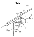
- Denoted by numeral 12 is a cowl panel of metal, which comprises an upper panel part 14 and a lower panel part 15. As shown, a rear flat portion of the upper panel part 14 and an upper flat portion of the lower panel part 15 are mated to constitute a horizontal holder structure 16 with which the catch devices 13 are engaged.
- the rear flat portion of the upper panel part 14 and the upper flat portion of the lower panel part 15 are spot-welded along a given narrow zone, and the rear flat portion of the upper panel part 14 is formed with a rectangular raised portion 23.
- the holder structure 16 comprises a first section where like the spot-welded zone the two panel parts 14 and 15 intimately contact at mutually facing surfaces thereof and a second section where like the rear end of the holder structure 16, the two panel parts 14 and 15 are spaced from each other at the mutually facing surfaces thereof. It is to be noted that the second section of the holder structure 16 is caught by a catch section 17 which will be described in detail hereinafter.
- a damper member 22 which has an exposed rounded part 22a formed on the rear end of the rear flat portion of the lower panel part 15, as shown in Fig. 6. It is to be noted that due to provision of the damper member 22 between the two panel parts 14 and 15, the resiliency of the holder structure 16 is increased. For placing the rounded part 22a of the damper member 22 on the rear end of the rear flat portion of the lower panel part 15, the rear flat portion of the upper panel part 14 is shaped shorter than the upper flat portion of the lower panel part 15, as shown in Fig. 6.
- the damper member 22 used is a waterproof material of a type that has a suitable resiliency. Thus, when the damper member 22 is applied between the upper and lower panel parts 14 and 15, it exhibits a suitable waterproof function in addition to the damper function. It is to be noted that due to presence of such damper member 22, undesired low frequency noises, which would be produced when the catch devices 13 make a play relative to the holder structure 16, are suppressed or at least minimized.
- each of the catch devices 13 generally comprises a catch section 17 and a guide section 18 which are positioned beside each other.
- Designated by numeral 19 is a box-like reinforcing structure defined by a lower surface of the instrument panel 11. With this reinforcing structure, the catch devices 13 are reinforced.
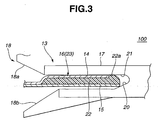
- the catch section 17 comprises a recess 21 having a mouth portion directed forward.
- the mouth of the recess 21 is so sized as to receive the rear end of the holder structure 16 on which the rounded part 22a of the elastic material 22 is mounted, as will be understood from the drawing of Fig. 3.
- the recess 21 of the catch section 17 has a sloped bottom 20, so that, when the rear end of the holder structure 16 is deeply and sufficiently inserted into the recess 21, the rounded part 22a of the damper member 22 is pressed against an upper inner surface of the recess 21, as is seen from the drawing.
- the guide section 18 comprises a generally triangular recess (no numeral) that is defined by sloped upper and lower surfaces 18a and 18b which are angled to each other. The mouth portion of this recess is also directed forward. If desired, the sloped upper and lower surfaces 18a and 18b may be concavely or convexly curved.
- the mouth portion of the catch section 17 is positioned behind the mouth portion of the guide section 18. More specifically, as is seen from Fig. 3, when viewed from a lateral side of the catch device 13, an intersecting part of the sloped upper and lower surfaces 18a and 18b of the guide section 18 is positioned behind the mouth portion of the catch section 17.
- the instrument panel 11 is conveyed behind the horizontal holder structure 16 of the cowl panel 12 the catch devices 13 facing forward, that is, toward the rear end of the holder structure 16 where the rectangular raised portion 23 is formed. Then, by the carrier, the instrument panel 11 is pushed forward by a certain distance. With this, the rear end of the holder structure 16 is brought into contact with the sloped upper and lower surfaces 18a and 18b of the guide section 18. Then, the instrument panel 11 is further pushed forward with a certain force. With this pushing, the rear end of the holder structure 16 is guided into the mouth portion of the catch section 17 of each catch device 13. As is seen from Fig.
- the work for assembling the instrument panel 11 onto the cowl panel 12 is easily and assuredly carried out.
- the rear ends of the holder structure 16 can be assuredly and stably held by the catch section 17.
- the holder structure 16 of the cowl panel 12 has an increased mechanical strength and thus assuredly and stably holds the instrument panel 11.
- a modification of the present invention there is shown a modification of the present invention.
- the holder structure 16 is not provided with the above-mentioned rectangular raised portion 23.
- the damper member 22 is substantially entirely disposed between the rear flat portion of the upper panel part 14 and the upper flat portion of the lower panel part 15. Furthermore, the rounded part 22a of the damper member 22 is turned back onto the rear end of the rear flat portion of the upper panel part 14, as shown.
Landscapes
- Engineering & Computer Science (AREA)
- Chemical & Material Sciences (AREA)
- Combustion & Propulsion (AREA)
- Transportation (AREA)
- Mechanical Engineering (AREA)
- Manufacturing & Machinery (AREA)
- Instrument Panels (AREA)
- Body Structure For Vehicles (AREA)
- Connection Of Plates (AREA)
Applications Claiming Priority (2)
| Application Number | Priority Date | Filing Date | Title |
|---|---|---|---|
| JP2000200440 | 2000-07-03 | ||
| JP2000200440A JP4184577B2 (ja) | 2000-07-03 | 2000-07-03 | 車両用インストルメントパネルの取付構造 |
Publications (3)
| Publication Number | Publication Date |
|---|---|
| EP1170166A2 true EP1170166A2 (fr) | 2002-01-09 |
| EP1170166A3 EP1170166A3 (fr) | 2003-09-24 |
| EP1170166B1 EP1170166B1 (fr) | 2005-02-09 |
Family
ID=18698317
Family Applications (1)
| Application Number | Title | Priority Date | Filing Date |
|---|---|---|---|
| EP01116109A Expired - Lifetime EP1170166B1 (fr) | 2000-07-03 | 2001-07-03 | Dispositif de montage d'un tableau de bord |
Country Status (4)
| Country | Link |
|---|---|
| US (1) | US6439652B2 (fr) |
| EP (1) | EP1170166B1 (fr) |
| JP (1) | JP4184577B2 (fr) |
| DE (1) | DE60108815T2 (fr) |
Cited By (4)
| Publication number | Priority date | Publication date | Assignee | Title |
|---|---|---|---|---|
| FR2881709A1 (fr) * | 2005-02-07 | 2006-08-11 | Faurecia Interieur Ind Snc | Sous-ensemble de planche de bord pour vehicule automobile |
| EP1666300A3 (fr) * | 2004-12-02 | 2008-01-30 | Seat, S.A. | Ancrage pour le montage de tableaux de bord sur la carrosserie d'un véhicule d'automobile |
| WO2017132934A1 (fr) * | 2016-02-04 | 2017-08-10 | Peugeot Citroen Automobiles Sa | Dispositif de guidage d'outil de fixation utilisé pour tableau de bord de véhicule |
| FR3103455A1 (fr) * | 2019-11-27 | 2021-05-28 | Renault S.A.S | Véhicule doté d’un dispositif de montage optimisé de la planche de bord |
Families Citing this family (17)
| Publication number | Priority date | Publication date | Assignee | Title |
|---|---|---|---|---|
| KR100376849B1 (ko) * | 2000-11-23 | 2003-03-19 | 현대자동차주식회사 | 자동차의 크러시패드어셈블리와 카울패널어셈블리의조립구조 |
| JP4694824B2 (ja) * | 2004-11-25 | 2011-06-08 | 大和化成工業株式会社 | 自動車のインストルメントパネル取付構造 |
| US7275497B2 (en) * | 2005-03-16 | 2007-10-02 | Denso International America, Inc. | Floating three-dimensional instrument panel dial structure |
| US7805815B2 (en) * | 2007-08-22 | 2010-10-05 | Toyota Motor Engineering & Manufacturing North America, Inc. | Clip |
| US7503608B1 (en) | 2008-01-10 | 2009-03-17 | Toyota Motor Engineering & Manufacturing North America, Inc. | Lead-in structures for front console assembly |
| JP5082999B2 (ja) * | 2008-04-07 | 2012-11-28 | トヨタ車体株式会社 | インストルメントパネルの取付構造 |
| US20090261613A1 (en) * | 2008-04-16 | 2009-10-22 | International Automotive Components Group North America, Inc. | Trim component with retention tabs |
| JP5107283B2 (ja) * | 2009-03-02 | 2012-12-26 | 大和化成工業株式会社 | クリップ |
| US20140073232A1 (en) * | 2012-09-12 | 2014-03-13 | Ford Global Technologies, Llc | Laterally Assembled Vehicle Duct Joint |
| CN104108435B (zh) * | 2013-04-16 | 2018-10-19 | 标致雪铁龙(中国)汽车贸易有限公司 | 一种用于安装仪表板部件的仪表板定位安装装置 |
| US8876197B1 (en) * | 2013-09-17 | 2014-11-04 | Ford Global Technologies, Llc | Instrument panel to body cowl attachment with pedestrian protection |
| US9481401B2 (en) * | 2014-05-09 | 2016-11-01 | Continental Automotive Systems, Inc. | Adjustable and flexible damper structure for instrument clusters |
| GB2540541B (en) * | 2015-07-20 | 2019-04-10 | Ford Global Tech Llc | A motor vehicle having an instrument panel |
| JP6870533B2 (ja) * | 2017-08-23 | 2021-05-12 | 株式会社オートネットワーク技術研究所 | 電気部品付ワイヤーハーネスおよび電気部品付ワイヤーハーネスの組付構造 |
| CN108274997B (zh) * | 2018-03-08 | 2020-06-02 | 北京汽车集团越野车有限公司 | 一种仪表板的安装结构及汽车 |
| FR3101056B1 (fr) * | 2019-09-25 | 2022-05-13 | Faurecia Interieur Ind | pièce d’assemblage pour connecter une planche de bord à une partie de caisse d’un véhicule |
| FR3153567A1 (fr) * | 2023-10-03 | 2025-04-04 | Psa Automobiles Sa | Planche de bord de véhicule automobile avec guide de montage |
Citations (2)
| Publication number | Priority date | Publication date | Assignee | Title |
|---|---|---|---|---|
| JPH11254999A (ja) | 1998-03-13 | 1999-09-21 | Suzuki Motor Corp | インストルメントパネルの取付構造 |
| JP2000200440A (ja) | 1999-01-06 | 2000-07-18 | Sankyo Seiki Mfg Co Ltd | 光源ユニットおよびそれを用いた光ピックアップ装置 |
Family Cites Families (11)
| Publication number | Priority date | Publication date | Assignee | Title |
|---|---|---|---|---|
| US2818933A (en) * | 1953-08-24 | 1958-01-07 | Gen Motors Corp | Vehicle cowl with two portion instrument panel |
| JPS5261822U (fr) * | 1975-10-31 | 1977-05-07 | ||
| FR2541958B1 (fr) * | 1983-02-25 | 1990-11-16 | Honda Motor Co Ltd | Tableau de bord perfectionne pour vehicules |
| DE3310886A1 (de) * | 1983-03-25 | 1984-09-27 | Volkswagenwerk Ag, 3180 Wolfsburg | Schalttafel fuer ein fahrzeug |
| DE3430121A1 (de) * | 1984-08-16 | 1986-02-27 | Gebr. Happich Gmbh, 5600 Wuppertal | Instrumententafel fuer kraftfahrzeuge |
| DE4134436C2 (de) * | 1990-10-29 | 1999-07-08 | Volkswagen Ag | Kraftfahrzeugkarosserie mit einem sich zwischen A-Säulen erstreckenden Vorderwandquerträger |
| JP2753444B2 (ja) * | 1993-05-14 | 1998-05-20 | 株式会社カンセイ | 車両用インストルメントパネル部構造 |
| JP3596554B2 (ja) * | 1994-08-18 | 2004-12-02 | 本田技研工業株式会社 | インストルメントパネルの取付構造 |
| DE29511172U1 (de) * | 1995-07-14 | 1996-02-01 | Peguform-Werke GmbH, 79268 Bötzingen | Kunststoffverkleidung für mit Luftsackeinrichtungen ausgestattete Fahrzeuge |
| DE19611192A1 (de) * | 1996-03-21 | 1997-09-25 | Daimler Benz Ag | Bauteil für den Innenraum von Kraftfahrzeugen |
| DE19807309B4 (de) * | 1998-02-20 | 2011-01-27 | Volkswagen Ag | Instrumententafel |
-
2000
- 2000-07-03 JP JP2000200440A patent/JP4184577B2/ja not_active Expired - Fee Related
-
2001
- 2001-07-03 EP EP01116109A patent/EP1170166B1/fr not_active Expired - Lifetime
- 2001-07-03 DE DE60108815T patent/DE60108815T2/de not_active Expired - Lifetime
- 2001-07-03 US US09/897,756 patent/US6439652B2/en not_active Expired - Fee Related
Patent Citations (2)
| Publication number | Priority date | Publication date | Assignee | Title |
|---|---|---|---|---|
| JPH11254999A (ja) | 1998-03-13 | 1999-09-21 | Suzuki Motor Corp | インストルメントパネルの取付構造 |
| JP2000200440A (ja) | 1999-01-06 | 2000-07-18 | Sankyo Seiki Mfg Co Ltd | 光源ユニットおよびそれを用いた光ピックアップ装置 |
Cited By (4)
| Publication number | Priority date | Publication date | Assignee | Title |
|---|---|---|---|---|
| EP1666300A3 (fr) * | 2004-12-02 | 2008-01-30 | Seat, S.A. | Ancrage pour le montage de tableaux de bord sur la carrosserie d'un véhicule d'automobile |
| FR2881709A1 (fr) * | 2005-02-07 | 2006-08-11 | Faurecia Interieur Ind Snc | Sous-ensemble de planche de bord pour vehicule automobile |
| WO2017132934A1 (fr) * | 2016-02-04 | 2017-08-10 | Peugeot Citroen Automobiles Sa | Dispositif de guidage d'outil de fixation utilisé pour tableau de bord de véhicule |
| FR3103455A1 (fr) * | 2019-11-27 | 2021-05-28 | Renault S.A.S | Véhicule doté d’un dispositif de montage optimisé de la planche de bord |
Also Published As
| Publication number | Publication date |
|---|---|
| US20020014788A1 (en) | 2002-02-07 |
| DE60108815D1 (de) | 2005-03-17 |
| EP1170166B1 (fr) | 2005-02-09 |
| JP4184577B2 (ja) | 2008-11-19 |
| JP2002012059A (ja) | 2002-01-15 |
| US6439652B2 (en) | 2002-08-27 |
| EP1170166A3 (fr) | 2003-09-24 |
| DE60108815T2 (de) | 2005-06-30 |
Similar Documents
| Publication | Publication Date | Title |
|---|---|---|
| US6439652B2 (en) | Instrument panel mounting structure | |
| CN101169147B (zh) | 外装部件的车体安装构造 | |
| JP3570481B2 (ja) | パネル取り付けコネクタ | |
| JPH07217604A (ja) | リザーブタンクの取付構造 | |
| JPH11245660A (ja) | 自動車用ウインドシールドパネルの位置決め構造 | |
| US5915767A (en) | Bumper side supporting structure | |
| JP2001289217A (ja) | クリップ | |
| JPH09185336A (ja) | 表示装置 | |
| JP4252881B2 (ja) | タンクプロテクタの固定構造 | |
| CN114834545B (zh) | 振动焊接成形品、振动焊接装置以及振动焊接成形品的制造方法 | |
| JP3093082B2 (ja) | 車両用部品取付クリップ | |
| KR100799390B1 (ko) | 특정 핀 접촉부에서의 전기적 접촉부 | |
| JPH09222109A (ja) | 樹脂成形部品の固定用クリップ | |
| JP3297629B2 (ja) | 自動車用ウインドシールドパネルの位置決め構造 | |
| JP6064848B2 (ja) | 自動車の内装構造 | |
| JP5088120B2 (ja) | 電気接続箱 | |
| JP3690153B2 (ja) | 自動車の内装部品の爪嵌合による連結構造 | |
| JP4390975B2 (ja) | クリップ | |
| JP3216366B2 (ja) | バンパモール取付構造 | |
| JPH09133118A (ja) | クリップ | |
| JP2002089911A (ja) | パイプ用ファン | |
| JPH106891A (ja) | バンパカバーとラジエータグリルの結合構造 | |
| JP3680666B2 (ja) | コネクタホルダ | |
| JP2000081116A (ja) | 自動変速機の鉄粉回収用マグネット固定構造 | |
| JP2516144B2 (ja) | 上側ガ―ニッシュと下側ガ―ニッシュとの連結溝造 |
Legal Events
| Date | Code | Title | Description |
|---|---|---|---|
| PUAI | Public reference made under article 153(3) epc to a published international application that has entered the european phase |
Free format text: ORIGINAL CODE: 0009012 |
|
| 17P | Request for examination filed |
Effective date: 20010703 |
|
| AK | Designated contracting states |
Kind code of ref document: A2 Designated state(s): AT BE CH CY DE DK ES FI FR GB GR IE IT LI LU MC NL PT SE TR |
|
| AX | Request for extension of the european patent |
Free format text: AL;LT;LV;MK;RO;SI |
|
| PUAL | Search report despatched |
Free format text: ORIGINAL CODE: 0009013 |
|
| AK | Designated contracting states |
Kind code of ref document: A3 Designated state(s): AT BE CH CY DE DK ES FI FR GB GR IE IT LI LU MC NL PT SE TR |
|
| AX | Request for extension of the european patent |
Extension state: AL LT LV MK RO SI |
|
| 17Q | First examination report despatched |
Effective date: 20040113 |
|
| AKX | Designation fees paid |
Designated state(s): DE FR GB |
|
| GRAP | Despatch of communication of intention to grant a patent |
Free format text: ORIGINAL CODE: EPIDOSNIGR1 |
|
| GRAS | Grant fee paid |
Free format text: ORIGINAL CODE: EPIDOSNIGR3 |
|
| GRAA | (expected) grant |
Free format text: ORIGINAL CODE: 0009210 |
|
| AK | Designated contracting states |
Kind code of ref document: B1 Designated state(s): DE FR GB |
|
| REG | Reference to a national code |
Ref country code: GB Ref legal event code: FG4D |
|
| REG | Reference to a national code |
Ref country code: IE Ref legal event code: FG4D |
|
| REF | Corresponds to: |
Ref document number: 60108815 Country of ref document: DE Date of ref document: 20050317 Kind code of ref document: P |
|
| PLBE | No opposition filed within time limit |
Free format text: ORIGINAL CODE: 0009261 |
|
| STAA | Information on the status of an ep patent application or granted ep patent |
Free format text: STATUS: NO OPPOSITION FILED WITHIN TIME LIMIT |
|
| ET | Fr: translation filed | ||
| 26N | No opposition filed |
Effective date: 20051110 |
|
| PGFP | Annual fee paid to national office [announced via postgrant information from national office to epo] |
Ref country code: GB Payment date: 20110629 Year of fee payment: 11 |
|
| PGFP | Annual fee paid to national office [announced via postgrant information from national office to epo] |
Ref country code: FR Payment date: 20110727 Year of fee payment: 11 |
|
| PGFP | Annual fee paid to national office [announced via postgrant information from national office to epo] |
Ref country code: DE Payment date: 20110629 Year of fee payment: 11 |
|
| GBPC | Gb: european patent ceased through non-payment of renewal fee |
Effective date: 20120703 |
|
| REG | Reference to a national code |
Ref country code: FR Ref legal event code: ST Effective date: 20130329 |
|
| PG25 | Lapsed in a contracting state [announced via postgrant information from national office to epo] |
Ref country code: GB Free format text: LAPSE BECAUSE OF NON-PAYMENT OF DUE FEES Effective date: 20120703 Ref country code: DE Free format text: LAPSE BECAUSE OF NON-PAYMENT OF DUE FEES Effective date: 20130201 Ref country code: FR Free format text: LAPSE BECAUSE OF NON-PAYMENT OF DUE FEES Effective date: 20120731 |
|
| REG | Reference to a national code |
Ref country code: DE Ref legal event code: R119 Ref document number: 60108815 Country of ref document: DE Effective date: 20130201 |