EP1170174A2 - Fixation par encliquetage d'un ensemble d'entrainement de miroir - Google Patents
Fixation par encliquetage d'un ensemble d'entrainement de miroir Download PDFInfo
- Publication number
- EP1170174A2 EP1170174A2 EP01116002A EP01116002A EP1170174A2 EP 1170174 A2 EP1170174 A2 EP 1170174A2 EP 01116002 A EP01116002 A EP 01116002A EP 01116002 A EP01116002 A EP 01116002A EP 1170174 A2 EP1170174 A2 EP 1170174A2
- Authority
- EP
- European Patent Office
- Prior art keywords
- drive housing
- mirror
- mirror support
- support
- connection
- Prior art date
- Legal status (The legal status is an assumption and is not a legal conclusion. Google has not performed a legal analysis and makes no representation as to the accuracy of the status listed.)
- Withdrawn
Links
- 239000011521 glass Substances 0.000 claims description 12
- 239000004020 conductor Substances 0.000 claims description 5
- 238000000034 method Methods 0.000 claims description 5
- 230000008569 process Effects 0.000 claims description 4
- 230000005540 biological transmission Effects 0.000 claims description 3
- 230000000295 complement effect Effects 0.000 claims 1
- 238000010079 rubber tapping Methods 0.000 description 4
- 239000000853 adhesive Substances 0.000 description 3
- 230000001070 adhesive effect Effects 0.000 description 3
- 230000008901 benefit Effects 0.000 description 2
- 238000004519 manufacturing process Methods 0.000 description 2
- 230000008439 repair process Effects 0.000 description 2
- 238000003780 insertion Methods 0.000 description 1
- 230000037431 insertion Effects 0.000 description 1
- 230000010354 integration Effects 0.000 description 1
- 239000000463 material Substances 0.000 description 1
- 239000002184 metal Substances 0.000 description 1
- 238000012986 modification Methods 0.000 description 1
- 230000004048 modification Effects 0.000 description 1
- 230000009467 reduction Effects 0.000 description 1
Images



Classifications
-
- B—PERFORMING OPERATIONS; TRANSPORTING
- B60—VEHICLES IN GENERAL
- B60R—VEHICLES, VEHICLE FITTINGS, OR VEHICLE PARTS, NOT OTHERWISE PROVIDED FOR
- B60R1/00—Optical viewing arrangements; Real-time viewing arrangements for drivers or passengers using optical image capturing systems, e.g. cameras or video systems specially adapted for use in or on vehicles
- B60R1/02—Rear-view mirror arrangements
- B60R1/06—Rear-view mirror arrangements mounted on vehicle exterior
- B60R1/062—Rear-view mirror arrangements mounted on vehicle exterior with remote control for adjusting position
- B60R1/07—Rear-view mirror arrangements mounted on vehicle exterior with remote control for adjusting position by electrically powered actuators
- B60R1/072—Rear-view mirror arrangements mounted on vehicle exterior with remote control for adjusting position by electrically powered actuators for adjusting the mirror relative to its housing
Definitions
- the present invention relates to an adjustable rearview mirror for a vehicle according to the preamble of claim 1.
- Such adjustable rear-view mirrors are widely used, particularly in the motor vehicle sector, with a mirror carrier connected by means of a device for mounting on a motor vehicle in a rotationally fixed is and in turn carries a drive housing.
- the drive housing comprises at least one drive unit, usually an electric motor, and possibly one or more gears.
- the drive housing is self-furrowing Screws attached to the mirror support.
- connection to the vehicle electrical system is usually made either via individual cables or via a plug connection, at least one connection each to the mirror support and to the drive housing provided and to be connected with each other.
- the object of the present invention is the known adjustable rearview mirror to further develop that a simple and inexpensive assembly of the drive housing on the mirror support is made possible, in particular at the same time an electrical connection is created between the mirror carrier and the drive housing.
- an adjustable rear view mirror in which electrical Contacts on the mirror support and the drive housing are designed so that during a Snap-in process for connecting the drive housing to the mirror support, at the same time electrical connection between the mirror carrier and the drive housing is established.
- conductor tracks are integrated on or in the mirror carrier, the contact points have for contacting the electrical contacts of the drive housing.
- This type of contacting represents a particularly simple, technically sensible and reliable way of contacting
- the mirror support for other electrical components such as side indicators, Sensors, GPS antenna, etc.
- is used as a feed line and possibly mounting surface is the integration of Conductor tracks make sense.
- Integrated conductor tracks are also better against external influences such as Moisture, etc., protected, so that the system as a whole is more reliable.
- the electrical contacts are each in a plug connection and received in a corresponding plug socket, the plug socket on the drive housing or on the mirror carrier and the connector corresponding on the mirror carrier or Drive housing are arranged.
- electrical components on the drive housing or on Mirror glass supports can also be controlled and operated using bus technology, which means the effort the number of wiring harnesses and the contacting effort significantly reduced.
- a plug socket is provided in such a way that when the snap segments snap into place a counter contour, which is attached to the mirror support, at the same time corresponding to the counter contour attached plug engages in the socket, so that with the process of mechanical Connecting by snapping or snapping an electrical connection between the Mirror carrier and the attached drive housing is made.
- the electrical contacts in particular plug connection and plug socket, can also be aligned in this way be that the direction of insertion of the plug or the contact with respect to the mounting direction of the Drive housing on the mirror support is rotated in particular by 90 °, with the contacting in a separate step from the snapping process.
- the drive housing is also attached to the mirror carrier by means of an adhesive connection provided alone or in combination with a snap fastening is.
- the snap connection of the drive housing is on the mirror support detachable, so that a repair of the drive housing and / or the mirror support is possible in a simple manner without one of the two parts being perceived as a hindrance or completely excludes a repair.
- the releasability of a snap attachment is ensured by the fact that the mirror support either from is accessible at the rear, so that the snap elements or segments snap from their fixing position can be pressed, or the catches of the snap segments with the help of a special tool solved, which is inserted from the front if the rear part of the mirror support is inaccessible.
- connection between the mirror support and the Drive housing designed to be non-rotatable and / or non-displaceable.
- This is particularly advantageous because because on both the drive housing and the mirror carrier when starting up in the Drive housing arranged at least one drive unit a torsional moment on the mirror support and / or the drive housing acts, so that a rotation of the mirror support against each other and the Drive housing or moving the two parts against each other possible and likely would be if the connection between the mirror carrier and the drive housing is not secured against rotation and / or is designed to be non-displaceable.
- means for establishing an electrical connection between the Mirror carrier and the drive housing especially a plug-socket arrangement, on and / or integral formed with the first and / or the second contour.
- the number of contour elements required for fastening the drive housing to the mirror carrier is at least so large that for each necessary electrical contact, respectively electrically necessary connection, a contour element is available.
- the Device according to the invention also several for the electrical connection of mirror carrier and drive housing have contours that are not required, or there may be additional separate electrical plug connections be provided in a connection of the drive housing and Grip the mirror supports together.
- the mirror carrier is in one piece formed with an element for mounting on the vehicle. It turns out in this embodiment especially advantageous that the drive housing in directly and without another intermediate piece Form of a device for mounting on the vehicle can be attached.
- the mirror support has a mirror head, which is attached to a mirror base attached to the vehicle is attached so that the number of parts required from initially a few self-tapping Screws and at least one intermediate piece for electrical contacting and the mirror support and the drive housing on two components, namely the one piece with a device for Mounting on a vehicle trained mirror carrier and the drive housing, is reduced, which not only faster assembly, but also a reduction in manufacturing costs.
- the mirror support separately on a device to be attached to a vehicle, whereby for example the advantage can be achieved that the mirror support and the drive housing universally on different devices for mounting on one Vehicle can be attached without regard to a coordination between the device for Assembly and the drive housing and mirror support must be taken.
- the rearview mirror has a spring device for securing the snap fastening of the drive housing to the mirror support.
- a spring device for securing the snap fastening of the drive housing to the mirror support.
- Such a spring device can, for example, be a spring ring made of metal or plastic, designed as a clip made of the appropriate materials or as a tight rubber sleeve be, which surrounds the drive housing and the mirror support in a suitable manner and to each other presses.
- the drive housing is pre-assembled before connection to the mirror support.
- a mirror glass support, one Power transmission device between the drive housing and the mirror glass carrier and a mirror glass are fully assembled and in this state by simply approaching the pre-assembled one Drive housing connectable to the mirror carrier.
- a connection of the pre-assembled is convenient Drive housing to the mirror carrier possible in a single step.
- Recesses that are provided on the drive housing and according to the invention as an anti-rotation device can also serve as screw-in recesses for an alternative fastening of the drive housing serve on the mirror support (screwing).
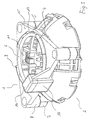
- FIG. 1 shows a mirror support 1 and a drive housing 2 of a motor vehicle rear-view mirror, the drive housing is suitable to snap into the mirror carrier and on this attached and to be fixed with a spring washer 6.
- the mirror support 1 has an essentially triangular base plate 15 downwardly projecting cylindrical feet 8, which for a plug connection with on the drive housing 2nd arranged recesses 7 are provided, and a connector pointing in the same direction 14 on.
- the base plate 15 has a circular opening 11, in the snap segments 9, which on which the mirror carrier 1 facing part of the drive housing 2 are fastened when inserted in engage the opening 11 of the mirror support 1.
- a socket 16 with electrical contacts 3 is formed on the drive housing 2 and has in the same direction as the snap segments 9, so that when the snap segments 9 snap into place behind the edge 17 of the opening 11 of the mirror support 1 at the same time an electrical contact in the connector 14 existing (hidden) electrical connections with those in the socket 16 corresponding electrical connections is ensured.
- the feet 8 engage in the Recesses 7 a. Both together create a rotatable and sliding connection between the mirror support 1 and the drive housing 2.
- FIG. 2 shows the mirror support 1 in a state in which a mirror glass support 10 is attached to it, on which a mirror plate can be attached.
- Fig. 3 the mounting state of the rearview mirror is shown, in which the snap segments 9 engage brought the edge 17 of the opening 11 of the mirror support 1 and with the metallic spring ring 6 so are fixed that prevents snapping or folding down from the plate 15 of the mirror support 1 is.
- Fig. 4 shows the arrangement with attached mirror glass carrier.
- the drive housing 2 can be released from the mirror support 1 in that the spring ring 6 by Finger pressure is removed and the snap segments 9 released from the opening 11, d. H. by easy Squeeze out.
- the invention is not only an adjustable rear view mirror with a means a snap and possibly an additional plug or adhesive connection attached drive housing and relates to a mirror support 1, but also an assembly method for connecting the drive housing with the mirror support.
Landscapes
- Engineering & Computer Science (AREA)
- Multimedia (AREA)
- Mechanical Engineering (AREA)
- Rear-View Mirror Devices That Are Mounted On The Exterior Of The Vehicle (AREA)
Applications Claiming Priority (2)
| Application Number | Priority Date | Filing Date | Title |
|---|---|---|---|
| DE10033088A DE10033088B4 (de) | 2000-07-07 | 2000-07-07 | Aufschnappen des Spiegelantriebes |
| DE10033088 | 2000-07-07 |
Publications (2)
| Publication Number | Publication Date |
|---|---|
| EP1170174A2 true EP1170174A2 (fr) | 2002-01-09 |
| EP1170174A3 EP1170174A3 (fr) | 2003-12-10 |
Family
ID=7648146
Family Applications (1)
| Application Number | Title | Priority Date | Filing Date |
|---|---|---|---|
| EP01116002A Withdrawn EP1170174A3 (fr) | 2000-07-07 | 2001-06-30 | Fixation par encliquetage d'un ensemble d'entrainement de miroir |
Country Status (3)
| Country | Link |
|---|---|
| US (1) | US6409353B1 (fr) |
| EP (1) | EP1170174A3 (fr) |
| DE (1) | DE10033088B4 (fr) |
Cited By (4)
| Publication number | Priority date | Publication date | Assignee | Title |
|---|---|---|---|---|
| FR2841844A1 (fr) * | 2002-07-02 | 2004-01-09 | Tokai Rika Co Ltd | Dispositif de retroviseur pour vehicule |
| WO2004009408A1 (fr) * | 2002-07-19 | 2004-01-29 | Magna Donnelly North America, L.L.C. | Mirroir arriere a connexion par encliquetage |
| NL1034697C2 (nl) * | 2007-11-14 | 2009-05-20 | Mci Mirror Controls Int Nl Bv | Montageconstructie voor een buitenspiegeleenheid. |
| WO2016099270A1 (fr) * | 2014-12-19 | 2016-06-23 | Mci (Mirror Controls International) Netherlands B.V. | Structure de dispositif de fixation, partie de rétroviseur extérieur, partie de carrosserie, unité rétroviseur extérieur, véhicule à moteur et procédé |
Families Citing this family (6)
| Publication number | Priority date | Publication date | Assignee | Title |
|---|---|---|---|---|
| US6758510B1 (en) * | 2003-04-04 | 2004-07-06 | Collins & Aikman Products Co. | Vehicle A-pillar trim components with integrated rear-view mirrors |
| DE102008034871A1 (de) * | 2008-07-26 | 2010-01-28 | Daimler Ag | Batterie, insbesondere Fahrzeugbatterie |
| EP2415640B1 (fr) * | 2010-08-03 | 2013-02-13 | SMR Patents S.à.r.l. | Rétroviseur extérieur et son procédé de montage |
| US20150097388A1 (en) * | 2013-10-07 | 2015-04-09 | GM Global Technology Operations LLC | Inside rearview mirror assembly |
| NL2012333B1 (en) * | 2014-02-28 | 2015-10-19 | MCI (Mirror Controls International) Netherlands B V | Mirror adjustment mechanism, in particular for a wing mirror for a motor vehicle. |
| DE102019100685B3 (de) * | 2019-01-11 | 2020-06-04 | Motherson Innovations Company Limited | Spiegelkomponente, Rückblickvorrichtung und Fahrzeug sowie Verfahren zum Einsetzen eines Stellglieds in eine Spiegelkomponente |
Citations (3)
| Publication number | Priority date | Publication date | Assignee | Title |
|---|---|---|---|---|
| US4840584A (en) * | 1988-02-05 | 1989-06-20 | Michael Cox | Mounting plate for attachment of electrical controls and accessories to walls and the like |
| US5604645A (en) * | 1995-03-17 | 1997-02-18 | United Technologies Automotive Systems | Mirror motor mounting bracket |
| DE19813039A1 (de) * | 1998-03-25 | 1999-10-07 | Buhler Motor Gmbh | Gehäuse, insbesondere eines Abklappantriebes für einen Kfz-Außenspiegel |
Family Cites Families (21)
| Publication number | Priority date | Publication date | Assignee | Title |
|---|---|---|---|---|
| US4056253A (en) * | 1974-05-16 | 1977-11-01 | Tenna Corporation | Adjustable mirror support |
| US4324454A (en) * | 1978-09-27 | 1982-04-13 | Murakami Kaimeido Co., Ltd. | Electric mirror angle adjusting device |
| US4921587A (en) * | 1985-09-19 | 1990-05-01 | H-D Tech, Inc. | Porous diaphragm for electrochemical cell |
| US4915493A (en) * | 1989-01-04 | 1990-04-10 | Magna International Inc. | Automotive rear view mirror assembly |
| US5183545A (en) * | 1989-04-28 | 1993-02-02 | Branca Phillip A | Electrolytic cell with composite, porous diaphragm |
| US4981279A (en) * | 1989-11-07 | 1991-01-01 | Sheller-Globe Corporation | Adjustable rear view mirror |
| DE9107365U1 (de) | 1991-06-14 | 1991-08-14 | Volkswagen AG, 3180 Wolfsburg | Verstellbarer Außenspiegel für ein Fahrzeug |
| US5610772A (en) | 1993-03-23 | 1997-03-11 | Ichikoh Industries Ltd. | Automobile sideview mirror |
| US5363246A (en) | 1993-05-12 | 1994-11-08 | United Technologies Automotive, Inc. | Power pack for an automotive exterior mirror assembly |
| US5467230A (en) * | 1993-08-16 | 1995-11-14 | Lowell Engineering Corp. | Dual pivoted member mount for mirror |
| FR2714638B3 (fr) | 1994-01-05 | 1996-05-03 | Gilardini Spa | Dispositif de support et d'orientation pour l'assemblage d'une plaque réfléchissante au corps d'un rétroviseur pour véhicule. |
| JP3007021B2 (ja) | 1995-04-04 | 2000-02-07 | 株式会社村上開明堂 | ドアミラー鏡面調整ユニットの支持装置 |
| DE19609017A1 (de) * | 1996-03-08 | 1997-09-11 | Reitter & Schefenacker Gmbh | Außenrückblickspiegel für Fahrzeuge, vorzugsweise für Kraftfahrzeuge |
| US5838507A (en) * | 1996-12-19 | 1998-11-17 | Lowell Engineering Corporation | Mirror assembly with friction drive |
| GB9702401D0 (en) * | 1997-02-06 | 1997-03-26 | Britax Rainsford Pty Limited | Vehicle rear view mirror |
| DE29810522U1 (de) | 1998-06-10 | 1998-10-08 | Magna Reflex Holding GmbH, 97959 Assamstadt | Fahrzeugspiegel |
| DE19841551B4 (de) * | 1998-09-11 | 2006-01-05 | Donnelly Hohe Gmbh & Co. Kg | Elektrischer Rückspiegel |
| NL1010513C2 (nl) * | 1998-11-09 | 2000-05-10 | Iku Holding Montfoort Bv | Elektrisch gestuurde spiegel voor een motorvoertuig. |
| DE19903378A1 (de) * | 1999-01-28 | 2000-08-24 | Mekra Lang Gmbh & Co Kg | Rückspiegel für Kraftfahrzeuge |
| NL1012092C2 (nl) * | 1999-05-18 | 2000-11-21 | Iku Holding Montfoort Bv | Spiegelactuatorhuisconstructie. |
| DE29915605U1 (de) | 1999-09-07 | 1999-12-23 | Donnelly Hohe GmbH & Co. KG, 97903 Collenberg | Außenrückspiegel mit elektrischer Steckverbindung |
-
2000
- 2000-07-07 DE DE10033088A patent/DE10033088B4/de not_active Expired - Lifetime
-
2001
- 2001-06-30 EP EP01116002A patent/EP1170174A3/fr not_active Withdrawn
- 2001-07-06 US US09/899,574 patent/US6409353B1/en not_active Expired - Fee Related
Patent Citations (3)
| Publication number | Priority date | Publication date | Assignee | Title |
|---|---|---|---|---|
| US4840584A (en) * | 1988-02-05 | 1989-06-20 | Michael Cox | Mounting plate for attachment of electrical controls and accessories to walls and the like |
| US5604645A (en) * | 1995-03-17 | 1997-02-18 | United Technologies Automotive Systems | Mirror motor mounting bracket |
| DE19813039A1 (de) * | 1998-03-25 | 1999-10-07 | Buhler Motor Gmbh | Gehäuse, insbesondere eines Abklappantriebes für einen Kfz-Außenspiegel |
Cited By (15)
| Publication number | Priority date | Publication date | Assignee | Title |
|---|---|---|---|---|
| FR2841844A1 (fr) * | 2002-07-02 | 2004-01-09 | Tokai Rika Co Ltd | Dispositif de retroviseur pour vehicule |
| US7033033B2 (en) | 2002-07-02 | 2006-04-25 | Kabushiki Kaisha Tokai-Rika-Denki-Seisakusho | Mirror device for a vehicle |
| WO2004009408A1 (fr) * | 2002-07-19 | 2004-01-29 | Magna Donnelly North America, L.L.C. | Mirroir arriere a connexion par encliquetage |
| US7448589B2 (en) | 2002-07-19 | 2008-11-11 | Magna Mirrors Of America, Inc. | Rear view mirror with snap connection |
| JP2011502880A (ja) * | 2007-11-14 | 2011-01-27 | エムシーアイ(ミラー コントロールズ インターナショナル)ネザーランド ベー.フェー. | 外部ミラーユニット用の取付構造 |
| WO2009064186A1 (fr) * | 2007-11-14 | 2009-05-22 | Mci (Mirror Controls International) Netherlands B.V. | Structure de montage pour une unité de miroir extérieure |
| NL1034697C2 (nl) * | 2007-11-14 | 2009-05-20 | Mci Mirror Controls Int Nl Bv | Montageconstructie voor een buitenspiegeleenheid. |
| US8534636B2 (en) | 2007-11-14 | 2013-09-17 | Mci (Mirror Controls International) Netherlands B.V. | Mounting construction for an outside mirror unit |
| EP2212155B1 (fr) | 2007-11-14 | 2017-03-08 | MCi (Mirror Controls International) Netherlands B.V. | Structure de montage pour une unité de miroir extérieure |
| WO2016099270A1 (fr) * | 2014-12-19 | 2016-06-23 | Mci (Mirror Controls International) Netherlands B.V. | Structure de dispositif de fixation, partie de rétroviseur extérieur, partie de carrosserie, unité rétroviseur extérieur, véhicule à moteur et procédé |
| NL2014026B1 (nl) * | 2014-12-19 | 2016-10-12 | MCI (Mirror Controls International) Netherlands B V | Bevestigingsconstructie, buitenspiegelonderdeel, carrosserieonderdeel, buitenspiegeleenheid, motorvoertuig en werkwijze. |
| CN107107827A (zh) * | 2014-12-19 | 2017-08-29 | 荷兰反光镜控制器国际有限公司 | 紧固结构、外后视镜部件、车身部件、外后视镜单元、机动车辆及方法 |
| CN107107827B (zh) * | 2014-12-19 | 2019-11-26 | 荷兰反光镜控制器国际有限公司 | 紧固结构、外后视镜部件、车身部件、外后视镜单元、机动车辆及方法 |
| US10493918B2 (en) | 2014-12-19 | 2019-12-03 | Mci (Mirror Controls International) Netherlands B.V. | Fastening construction, exterior mirror part, body part, exterior mirror unit, motor vehicle, and method |
| DE112015005660B4 (de) | 2014-12-19 | 2022-02-17 | Mci (Mirror Controls International) Netherlands B.V. | Befestigungsanordnung, Außenspiegelteil, Karosserieteil, Außenspiegeleinheit, Kraftfahrzeug und Verfahren |
Also Published As
| Publication number | Publication date |
|---|---|
| EP1170174A3 (fr) | 2003-12-10 |
| US20020024751A1 (en) | 2002-02-28 |
| DE10033088B4 (de) | 2005-12-22 |
| US6409353B1 (en) | 2002-06-25 |
| DE10033088A1 (de) | 2002-01-31 |
Similar Documents
| Publication | Publication Date | Title |
|---|---|---|
| EP2117890B1 (fr) | Entraînement électrique | |
| EP0687593B2 (fr) | Dispositif électrique pour véhicules automobiles, en particulier interrupteur monté sur la colonne de direction | |
| DE19801526C2 (de) | Kombinationsschaltvorrichtung | |
| EP0853022B1 (fr) | Module de fonction pour véhicule. | |
| DE102015107385A1 (de) | Verfahren zum Herstellen einer Kamera für ein Kraftfahrzeug mit elektrischem Verbinden einer Leiterplatte und einem Linsengehäuse, Kamera, Fahrerassistenzsystem sowieKraftfahrzeug | |
| EP1170174A2 (fr) | Fixation par encliquetage d'un ensemble d'entrainement de miroir | |
| DE69013221T2 (de) | Hilfsplatine am Armaturenbrett eines Kraftfahrzeugs. | |
| EP1608994B1 (fr) | Ensemble capteur d'un systeme d'aide au stationnement | |
| EP0888928A1 (fr) | Miroir rétroviseur de véhicule à réglage motorisé | |
| DE29905025U1 (de) | Verteiler zum Verbinden von Aktoren und/oder Sensoren | |
| DE3428922C2 (de) | Mehrpolige, lösbare Steckverbindung zum Übertragen von elektrischen Strömen, vorzugsweise zur Verwendung an Kraftfahrzeugen | |
| DE4427883C1 (de) | Einrichtung für Kraftfahrzeuge | |
| DE102015105531A1 (de) | Kamera für ein Kraftfahrzeug mit elektrisch leitendem Kontaktelement, Fahrerassistenzsystem, Kraftfahrzeug sowie Verfahren | |
| DE102015110262A1 (de) | Kamera für ein Kraftfahrzeug mit Abschirmeinrichtung, Fahrerassistenzsystem sowie Kraftfahrzeug | |
| DE69504388T2 (de) | Kraftfahrzeuglenksäulen-Schaltergehäuse | |
| DE69911990T2 (de) | Elektrisch gesteuerter kraftfahrzeug- rückblickspiegel | |
| EP0412418B1 (fr) | Bouton de demande d'arrêt | |
| DE10214609B4 (de) | Lenkrad für ein Fahrzeug | |
| DE19812417A1 (de) | Verfahren zur Montage einer elektrischen Baugruppe innerhalb eines Kraftfahrzeugs sowie elektrische Baugruppe | |
| EP1986281A1 (fr) | Procédé de fabrication d'une liaison électrique conductrice | |
| DE102010050613B4 (de) | Kraftfahrzeug mit einer Kamera für ein Fahrerassistenzsystem | |
| WO2008058807A1 (fr) | Dispositif de connexion pour un mécanisme de commande auxiliaire d'un véhicule | |
| DE102023132202A1 (de) | Befestigung von Steuergeräten | |
| DE102015122659A1 (de) | Elektrische Schaltung | |
| DE19739296C2 (de) | Funktionsmodul |
Legal Events
| Date | Code | Title | Description |
|---|---|---|---|
| PUAI | Public reference made under article 153(3) epc to a published international application that has entered the european phase |
Free format text: ORIGINAL CODE: 0009012 |
|
| AK | Designated contracting states |
Kind code of ref document: A2 Designated state(s): AT BE CH CY DE DK ES FI FR GB GR IE IT LI LU MC NL PT SE TR |
|
| AX | Request for extension of the european patent |
Free format text: AL;LT;LV;MK;RO;SI |
|
| PUAL | Search report despatched |
Free format text: ORIGINAL CODE: 0009013 |
|
| AK | Designated contracting states |
Kind code of ref document: A3 Designated state(s): AT BE CH CY DE DK ES FI FR GB GR IE IT LI LU MC NL PT SE TR |
|
| AX | Request for extension of the european patent |
Extension state: AL LT LV MK RO SI |
|
| 17P | Request for examination filed |
Effective date: 20031128 |
|
| AKX | Designation fees paid |
Designated state(s): AT BE CH CY DE DK ES FI FR GB GR IE IT LI LU MC NL PT SE TR |
|
| 17Q | First examination report despatched |
Effective date: 20050531 |
|
| 17Q | First examination report despatched |
Effective date: 20050531 |
|
| GRAP | Despatch of communication of intention to grant a patent |
Free format text: ORIGINAL CODE: EPIDOSNIGR1 |
|
| STAA | Information on the status of an ep patent application or granted ep patent |
Free format text: STATUS: THE APPLICATION HAS BEEN WITHDRAWN |
|
| 18W | Application withdrawn |
Effective date: 20080624 |