EP1170408A1 - Rotorspinnvorrichtung mit einer berührungslosen passiven radialen Lagerung des Spinnrotors - Google Patents
Rotorspinnvorrichtung mit einer berührungslosen passiven radialen Lagerung des Spinnrotors Download PDFInfo
- Publication number
- EP1170408A1 EP1170408A1 EP01109083A EP01109083A EP1170408A1 EP 1170408 A1 EP1170408 A1 EP 1170408A1 EP 01109083 A EP01109083 A EP 01109083A EP 01109083 A EP01109083 A EP 01109083A EP 1170408 A1 EP1170408 A1 EP 1170408A1
- Authority
- EP
- European Patent Office
- Prior art keywords
- rotor
- actuator
- elements
- spinning
- actuators
- Prior art date
- Legal status (The legal status is an assumption and is not a legal conclusion. Google has not performed a legal analysis and makes no representation as to the accuracy of the status listed.)
- Granted
Links
- 238000007383 open-end spinning Methods 0.000 title claims abstract description 15
- 238000009987 spinning Methods 0.000 claims abstract description 22
- 238000013016 damping Methods 0.000 claims description 47
- 230000010355 oscillation Effects 0.000 abstract 1
- 230000000694 effects Effects 0.000 description 6
- XEEYBQQBJWHFJM-UHFFFAOYSA-N Iron Chemical group [Fe] XEEYBQQBJWHFJM-UHFFFAOYSA-N 0.000 description 2
- 239000003990 capacitor Substances 0.000 description 2
- 238000001514 detection method Methods 0.000 description 2
- 238000000034 method Methods 0.000 description 2
- 238000005457 optimization Methods 0.000 description 2
- 230000003068 static effect Effects 0.000 description 2
- 230000032683 aging Effects 0.000 description 1
- 230000033228 biological regulation Effects 0.000 description 1
- 238000010276 construction Methods 0.000 description 1
- 230000003111 delayed effect Effects 0.000 description 1
- 230000001419 dependent effect Effects 0.000 description 1
- 230000003993 interaction Effects 0.000 description 1
- 238000012423 maintenance Methods 0.000 description 1
- 239000000463 material Substances 0.000 description 1
- 238000012545 processing Methods 0.000 description 1
- 230000006641 stabilisation Effects 0.000 description 1
- 238000011105 stabilization Methods 0.000 description 1
- 238000012549 training Methods 0.000 description 1
- 238000012546 transfer Methods 0.000 description 1
Images



Classifications
-
- F—MECHANICAL ENGINEERING; LIGHTING; HEATING; WEAPONS; BLASTING
- F16—ENGINEERING ELEMENTS AND UNITS; GENERAL MEASURES FOR PRODUCING AND MAINTAINING EFFECTIVE FUNCTIONING OF MACHINES OR INSTALLATIONS; THERMAL INSULATION IN GENERAL
- F16F—SPRINGS; SHOCK-ABSORBERS; MEANS FOR DAMPING VIBRATION
- F16F15/00—Suppression of vibrations in systems; Means or arrangements for avoiding or reducing out-of-balance forces, e.g. due to motion
- F16F15/10—Suppression of vibrations in rotating systems by making use of members moving with the system
- F16F15/18—Suppression of vibrations in rotating systems by making use of members moving with the system using electric, magnetic or electromagnetic means
-
- D—TEXTILES; PAPER
- D01—NATURAL OR MAN-MADE THREADS OR FIBRES; SPINNING
- D01H—SPINNING OR TWISTING
- D01H4/00—Open-end spinning machines or arrangements for imparting twist to independently moving fibres separated from slivers; Piecing arrangements therefor; Covering endless core threads with fibres by open-end spinning techniques
- D01H4/04—Open-end spinning machines or arrangements for imparting twist to independently moving fibres separated from slivers; Piecing arrangements therefor; Covering endless core threads with fibres by open-end spinning techniques imparting twist by contact of fibres with a running surface
- D01H4/08—Rotor spinning, i.e. the running surface being provided by a rotor
- D01H4/12—Rotor bearings; Arrangements for driving or stopping
-
- F—MECHANICAL ENGINEERING; LIGHTING; HEATING; WEAPONS; BLASTING
- F16—ENGINEERING ELEMENTS AND UNITS; GENERAL MEASURES FOR PRODUCING AND MAINTAINING EFFECTIVE FUNCTIONING OF MACHINES OR INSTALLATIONS; THERMAL INSULATION IN GENERAL
- F16C—SHAFTS; FLEXIBLE SHAFTS; ELEMENTS OR CRANKSHAFT MECHANISMS; ROTARY BODIES OTHER THAN GEARING ELEMENTS; BEARINGS
- F16C32/00—Bearings not otherwise provided for
- F16C32/04—Bearings not otherwise provided for using magnetic or electric supporting means
- F16C32/0406—Magnetic bearings
- F16C32/0408—Passive magnetic bearings
-
- F—MECHANICAL ENGINEERING; LIGHTING; HEATING; WEAPONS; BLASTING
- F16—ENGINEERING ELEMENTS AND UNITS; GENERAL MEASURES FOR PRODUCING AND MAINTAINING EFFECTIVE FUNCTIONING OF MACHINES OR INSTALLATIONS; THERMAL INSULATION IN GENERAL
- F16C—SHAFTS; FLEXIBLE SHAFTS; ELEMENTS OR CRANKSHAFT MECHANISMS; ROTARY BODIES OTHER THAN GEARING ELEMENTS; BEARINGS
- F16C2340/00—Apparatus for treating textiles
- F16C2340/18—Apparatus for spinning or twisting
Definitions
- the invention relates to a rotor spinning device with a Non-contact passive radial bearing of the spinning rotor according to the preamble of claim 1.
- the generic DE 198 19 767 A1 describes one Damping device for passive radial bearings from Spinning rotors.
- the damping takes place by means of a Friction device, the friction partner mechanically actable Have friction surfaces.
- One of the friction partners is radial arranged in a fixed position on one bearing part, and the other The friction partner is held in a position that can be changed radially.
- the radial position-adjustable friction partner has a bearing component, which encloses the rotor shaft of the rotor. Through this Bearing component, the appearance becomes large Vibration amplitudes in which the rotor on the stator can strike, avoided.
- the damping sets the occurring vibrations in friction.
- a particularly low construction effort is sufficient for one device according to the invention because the rotating Magnetic element on which the actuator elements act Active element of the passive bearing of the spinning rotor is.
- the Effective point is close to to improve the damping effect End of the rotor shaft.
- the sensor system comprises the effective point at least two sensor elements for detection radial positional deviations of the rotor shaft and are the Sensor elements and the actuator elements of the active site in one arranged perpendicular to the plane of rotation spanned plane.
- the actuator elements for the sensor elements are preferred Effective point arranged at an angle in the direction of rotation.
- Two actuator elements to one another and two are advantageous Sensor elements to each other in the direction of rotation by 90 ° arranged at an angle. This makes it structurally compact Training of the damping device without much effort possible.
- the detection of the radial positional deviations as well as the Actuator control can be carried out simply and precisely.
- the control device is designed so that the angular offset of actuator elements and sensor elements in a simple manner signal processing can be taken into account.
- Each actuator element is one with respect to the axis of rotation diametrically opposite additional actuator element assigned and the rotating magnetic element from Actuator element and the additional actuator element each with the applied the same force, the damping effect Double power in a simple way.
- the actuator element and Additional actuator element force is both in Amount same as in the same direction. With this version can be on the rotating magnetic element and thus the static magnetic forces acting on the rotor shaft neutralize that when using actuator elements occur, each with a magnetic coil with an iron core Have generation of effective magnetic forces.
- the rotating magnetic element is a Permanent magnet ring surrounding the rotor shaft, and the actuator elements are preferably axially spaced from the Permanent magnet ring arranged. That way they can Actuator elements very close to the rotating magnetic element brought and the air gap between the magnetic element and Actuator element can be kept small without the bandages around the outer circumference of the magnetic element are a hindrance.
- Bandages are usually used at high speed revolving spinning rotors placed around the magnetic rings. ever less the air gap between actuator element and magnetic element the higher the effectiveness of the damping that is achieved can be.
- the control device preferably has elements which are used for only capacitive decoupling of the Signals generated by sensor elements are used. At a such execution will only be the dynamic Transfer signal components. This affects Zero point error of the sensor elements not out. Through the Restriction to the AC components flow only slightly Currents, however, sufficient for the regulation of the damping are high.
- the damping can be achieved with the device according to the invention radial vibrations compared to known devices improve significantly.
- the desired optimum damping leaves always without problems without lengthy optimization procedures meet because the damping effect is reproducible.
- the without Delay and effective damping can be achieved with the Invention can be achieved without much effort.
- the known rotor spinning device 1 comprises a spinning rotor 2, the spinning cup of which rotates in a rotor housing 3 at high speed.
- the spinning rotor is driven by an electric individual drive 4.
- the spinning rotor 2 is fixed with its rotor shaft 5 both radially and axially in a magnetic bearing 6.
- the opening of the rotor housing 3 is closed during the spinning process by a pivotably mounted cover element 7.
- the magnetic bearing 6 is a passive spinning rotor bearing. Further details of a contactless passive spinning rotor bearing can be found, for example, in DE 198 19 767 A1 already mentioned.
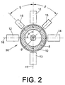
- FIG. 2 shows the one shown in FIG. 2 as a permanent magnet ring trained magnetic element 8 .
- the front view of the Figure 2 visible pole side of the permanent magnet ring is N characterized.
- the magnetic element 8 is with a bandage 10 surround.
- FIG. 2 shows the position of the actuator elements 11, 12, 13 and 14 and the sensor elements 15 and 16. Die Sensor elements 15, 16 and the actuator elements 11, 12, 13, 14 are in a perpendicular to the axis of rotation of the rotor shaft 9 spanned plane.
- the angle ⁇ between that Actuator element 11 and the actuator element 12 is 90 °.
- the Angle ⁇ between the sensor elements 15, 16 and the Actuator element 11 is 45 ° in each case.
- the actuator elements 11 and 13 act in the direction of the damping axis 17, and Actuator elements 12 and 14 act in the direction of Damping axis 18. Basically, it is enough for everyone Damping axis 17, 18 to use only a single actuator. With the embodiment shown in Figure 2 with each diametrically opposite actuator elements 11, 13; 12, 14 higher damping effectiveness can be achieved.
- Figure 3 shows that firmly connected to the rotor shaft 9 Magnetic element 8 in side view. During spinning runs the magnetic element 8 at high speed. For storage of the rotor shaft 9, the magnetic element 8 acts with a stationary also designed as a permanent magnet ring Magnetic element 19 together.
- the actuator element 11 is in the Representation of Figure 3 arranged above the magnetic element 8.
- the actuator element 11 also has a pole N and one Opposite pole S on.
- the actuator element 12 is the actuator element 11 arranged diametrically opposite, in the representation of Figure 3 under the magnetic element 8.
- the active site 30 with the Magnetic element 8 is close to the end 20 of the rotor shaft 9. Die Actuator elements 11, 13, 12, 14 each have magnetic coils Iron cores on.
- Figure 4 shows an alternative embodiment in which the Actuator element 11 'occupies a position in which the N designated pole of the actuator element 11 ′ the magnetic element 8 is facing.
- Figure 5 shows a further alternative embodiment.
- the Actuator element 11 '' is axially spaced in front of the Arranged magnetic element 8.
- the air gap between Actuator element 11 '' and the magnetic element 8 is relatively small held. Setting a very small air gap will not hindered by the bandage 10 in this embodiment.
- Figures 6 and 7 show control loops for controlling the interacting actuator elements 11 and 13 and the interacting actuator elements 12 and 14 of those in FIGS and 3 shown device.
- Signals generated by sensor element 15 are used by a capacitor 21, the via the resistor 23 and the amplifier 25 to the signal forwards the control device 27.
- To decouple the from The sensor element 16 generated signal is the capacitor 22 arranged via the resistor 24 and the amplifier 26th forwards the signal to the control device 27.
- the of the amplifiers 25 and 26 to the control device 27 guided signals are added. In this way the Angular offset between the sensor elements 15 and 16 and the Actuator elements 11 and 13 are taken into account.
- the sensor elements 15 and 16 work inductively.
- the amplifier 26 operates to control the actuator elements 12 and 14 as a negating amplifier.
- the damping process will depending on the sensor elements 15 and 16 generated signals controlled by the strength of the current, each via the amplifiers 28, 29 to the Actuator elements 11, 13 and the actuator elements 12, 14 passed becomes.
- Actuator elements 11, 13, 12, 14 take place. That way that acted on the rotor shaft 9 for damping Magnetic force controlled in both strength and direction become.
- the poles of the actuator element 11 are as in FIG. 3 shown aligned when a by vibration Deflection of the rotor shaft 9 occurs, in which the position of the Rotor shaft 9 from the target position in the representation of Figure 3 deviates downwards. Due to the position of the poles of the Actuator element 11 pulls the actuator element 11 as Permanent magnet ring formed magnetic element 8an while the actuator element 13 repels the magnetic element 8. To this The positional deviation caused by vibration becomes wise counteracted and thus dampened the vibration.
- the actuator elements 11 and 13 or 12 and 14 can as shown in Figures 6 and 7, in series or in one Alternative embodiment, not shown, in parallel be switched.
Landscapes
- Engineering & Computer Science (AREA)
- General Engineering & Computer Science (AREA)
- Mechanical Engineering (AREA)
- Physics & Mathematics (AREA)
- Electromagnetism (AREA)
- Acoustics & Sound (AREA)
- Aviation & Aerospace Engineering (AREA)
- Textile Engineering (AREA)
- Magnetic Bearings And Hydrostatic Bearings (AREA)
Abstract
Description
- Fig. 1
- in Seitenansicht eine schematische Darstellung einer Rotorspinnvorrichtung mit einer berührungslosen passiven Spinnrotorlagerung, teilweise im Schnitt,
- Fig. 2
- eine schematische Darstellung der Anordnung von Sensorelementen und Aktorelementen an einer Wirkstelle der Dämpfungseinrichtung einer Rotorspinnvorrichtung, in Vorderansicht,
- Fig. 3
- eine schematische Darstellung der Anordnung eines Aktorelementes an der in Figur 2 gezeigten Wirkstelle, in Seitenansicht,
- Fig. 4
- eine Darstellung einer alternativen Anordnung eines Aktorelementes, entsprechend der Ansicht von Figur 3,
- Fig. 5
- eine Darstellung einer weiteren alternativen Anordnung eines Aktorelementes, entsprechend der Ansicht von Figur 3,
- Fig. 6
- eine schematische Darstellung einer ersten Regelschleife mit den beiden Sensorelementen und zwei Aktorelementen der Darstellung der Figur 2,
- Fig. 7
- eine schematische Darstellung einer zweiten Regelschleife mit den beiden Sensorelementen und zwei weiteren Aktorelementen der Darstellung der Figur 2.
Weitere Einzelheiten einer berührungslosen passiven Spinnrotorlagerung sind zum Beispiel der bereits genannten DE 198 19 767 A1 entnehmbar.
Claims (7)
- Rotorspinnvorrichtung mit einer berührungslosen passiven radialen Lagerung des Spinnrotors und mit einer Dämpfungseinrichtung, die zur Dämpfung von radial gerichteten Schwingungen des Spinnrotors ausgebildet ist, wobei die Dämpfungseinrichtung eine Sensoreinrichtung, eine Regeleinrichtung und eine Aktoreinrichtung umfaßt und die Aktoreinrichtung so ausgeführt ist, daß sie an mindestens einer Wirkstelle (30) auf den Rotorschaft (9) einwirkt,
dadurch gekennzeichnet, daß sie an der Wirkstelle (30) mindestens zwei ortsfeste als Magnetelemente ausgebildete Aktorelemente (11, 12) aufweist, die unmittelbar auf ein fest mit dem rotierenden Rotorschaft (9) verbundenes Magnetelement (8) wirken, wobei das rotierende Magnetelement (8) ein Wirkelement der passiven Lagerung des Spinnrotors ist. - Rotorspinnvorrichtung nach Anspruch 1, dadurch gekennzeichnet, daß das von der Aktoreinrichtung beaufschlagte rotierende Magnetelement (8) so angeordnet ist, daß die Sensorik an der Wirkstelle mindestens zwei Sensorelemente (15, 16) zur Detektion radialer Lageabweichung des Rotorschaftes (9) umfaßt und daß die Sensorelemente (15, 16) und die Aktorelemente (11, 12) der Wirkstelle in einer senkrecht zur Rotationsachse aufgespannten Ebene angeordnet sind.
- Rotorspinnvorrichtung nach Anspruch 1 oder 2, dadurch gekennzeichnet, daß die Aktorelemente zu den Sensorelementen (15, 16) der Wirkstelle (30) in Rotationsrichtung winkelversetzt angeordnet sind.
- Rotorspinnvorrichtung nach Anspruch 2 oder 3, dadurch gekennzeichnet, daß die zwei Aktorelemente (11, 12) zueinander und die zwei Sensorelemente (15, 16) zueinander in Rotationsrichtung jeweils um 90 Grad winkelversetzt angeordnet sind.
- Rotorspinnvorrichtung nach einem der vorhergehenden Ansprüche, dadurch gekennzeichnet, daß jedem Aktorelement (11, 12) ein in bezug auf die Rotationsachse diametral gegenüberliegendes zusätzliches Aktorelement (13, 14) zugeordnet ist und daß das Aktorelement (11, 12) und das zusätzliche Aktorelement (13, 14) das rotierende Magnetelement (8) jeweils mit einer gleichgroßen und gleichgerichteten Kraft beaufschlagen.
- Rotorspinnvorrichtung nach einem der vorhergehenden Ansprüche, dadurch gekennzeichnet, daß das rotierende Magnetelement (8) als ein den Rotorschaft (9) umschließender Permanentmagnetring ausgebildet ist und daß die Aktorelemente (11, 12, 13, 14) axial beabstandet vor dem Permanentmagnetring angeordnet sind.
- Rotorspinnvorrichtung nach einem der vorhergehenden Ansprüche, dadurch gekennzeichnet, daß die Regeleinrichtung (27) Elemente aufweist, die zur ausschließlich kapazitiven Auskopplung der von den Sensorelementen (15, 16) generierten Signale dienen.
Applications Claiming Priority (2)
| Application Number | Priority Date | Filing Date | Title |
|---|---|---|---|
| DE10032440 | 2000-07-04 | ||
| DE10032440A DE10032440A1 (de) | 2000-07-04 | 2000-07-04 | Rotorspinnvorrichtung mit einer berührungslosen passiven radialen Lagerung des Spinnrotors |
Publications (2)
| Publication Number | Publication Date |
|---|---|
| EP1170408A1 true EP1170408A1 (de) | 2002-01-09 |
| EP1170408B1 EP1170408B1 (de) | 2004-09-01 |
Family
ID=7647726
Family Applications (1)
| Application Number | Title | Priority Date | Filing Date |
|---|---|---|---|
| EP01109083A Expired - Lifetime EP1170408B1 (de) | 2000-07-04 | 2001-04-12 | Rotorspinnvorrichtung mit einer berührungslosen passiven radialen Lagerung des Spinnrotors |
Country Status (4)
| Country | Link |
|---|---|
| US (1) | US6720695B2 (de) |
| EP (1) | EP1170408B1 (de) |
| CZ (1) | CZ300545B6 (de) |
| DE (2) | DE10032440A1 (de) |
Cited By (4)
| Publication number | Priority date | Publication date | Assignee | Title |
|---|---|---|---|---|
| WO2010020204A1 (de) * | 2008-08-16 | 2010-02-25 | Forschungszentrum Jülich GmbH | Magnetführungseinrichtung mit elektromagnetischer dämpfung |
| EP2781775A1 (de) * | 2013-03-22 | 2014-09-24 | Rieter CZ s.r.o. | Verfahren zur Erkennung von Positionsänderungen von wellenlosem Spinnrotor einer Open-End-Spinnmaschine im Innenraum eines aktiven Magnetlagers und Spinneinheit mit aktivem Magnetlager zur Lagerung des wellenlosen Spinnrotors |
| CN104864030A (zh) * | 2015-04-09 | 2015-08-26 | 清华大学 | 一种小型复合材料转子振动控制方法 |
| EP3179121A1 (de) * | 2015-12-11 | 2017-06-14 | Saurer Germany GmbH & Co. KG | Elektrischer antrieb und offenend-spinneinrichtung mit dem elektrischen antrieb |
Families Citing this family (18)
| Publication number | Priority date | Publication date | Assignee | Title |
|---|---|---|---|---|
| DE102004005846A1 (de) | 2004-02-06 | 2005-08-25 | Saurer Gmbh & Co. Kg | Rotorschaft eines Spinnrotors |
| BRPI0511385A (pt) * | 2004-06-15 | 2007-12-04 | Aly El-Shafei | métodos para controlar a instabilidade em rolamentos de pelìcula de fluido |
| US8533777B2 (en) * | 2004-12-29 | 2013-09-10 | Intel Corporation | Mechanism to determine trust of out-of-band management agents |
| US7126244B2 (en) * | 2004-12-30 | 2006-10-24 | Rozlev Corp., Llc | Magnetic bearing assembly using repulsive magnetic forces |
| US7327060B2 (en) * | 2004-12-30 | 2008-02-05 | Rozlev Corp., Llc | Bearing assembly having a mechanical component and using attractive magnetic forces |
| US7391128B2 (en) * | 2004-12-30 | 2008-06-24 | Rozlev Corp., Llc | Wind generator system using attractive magnetic forces to reduce the load on the bearings |
| DE102008016745B4 (de) | 2008-04-02 | 2014-04-03 | Saurer Germany Gmbh & Co. Kg | Lagereinrichtung für einen Spinnrotor |
| KR101781010B1 (ko) * | 2010-09-01 | 2017-10-23 | 레비트로닉스 게엠베하 | 회전 펌프 |
| CN201947080U (zh) * | 2011-01-28 | 2011-08-24 | 中山大洋电机制造有限公司 | 一种无刷电机转子结构 |
| PL394800A1 (pl) | 2011-05-06 | 2012-11-19 | Pawel Krzysztof Licznerski | Lozysko magnetyczne i sposób dzialania lozyska magnetycznego |
| EP3458733B1 (de) | 2016-05-17 | 2024-07-03 | Aly El-Shafei | Integriertes zapfenlager |
| DE102018117861A1 (de) * | 2018-07-24 | 2020-01-30 | Saurer Spinning Solutions Gmbh & Co. Kg | Offenend-Rotorspinnvorrichtung |
| DE102019112735A1 (de) * | 2019-05-15 | 2020-11-19 | Maschinenfabrik Rieter Ag | Verfahren zur Identifikation eines Spinnrotors an einer Rotorspinnmaschine sowie Rotorspinnmaschine |
| CN110453322B (zh) * | 2019-08-29 | 2024-03-08 | 扬州大学 | 一种用于纺纱锭子的分离式永磁悬浮轴承结构 |
| US11585235B2 (en) | 2020-11-18 | 2023-02-21 | Rolls-Royce North American Technologies Inc. | Magnetic shaft mode control |
| ES2985149T3 (es) * | 2021-05-15 | 2024-11-04 | Sanko Tekstil Isletmeleri San Tic A S | Dispositivo y método para enrollar y torcer material de fibra en armazones de hilatura de anillos o torsión de anillos |
| FR3141209B1 (fr) * | 2022-10-24 | 2025-01-17 | Safran Aircraft Engines | Système de correction d’un mouvement de précession d’un arbre d’une turbomachine, turbomachine et procédé associés |
| CN118109931B (zh) * | 2024-03-15 | 2025-02-14 | 浙江自力机械有限公司 | 一种用于倍捻机上的锭子 |
Citations (6)
| Publication number | Priority date | Publication date | Assignee | Title |
|---|---|---|---|---|
| US3650581A (en) * | 1969-06-30 | 1972-03-21 | Karl Boden Wilhelm Groth & Die | Bearing systems |
| US3845997A (en) * | 1972-03-20 | 1974-11-05 | Padana Ag | Magnetic bearing assembly for journalling a rotor in a stalor |
| US4037886A (en) * | 1974-04-30 | 1977-07-26 | Padana Ag | Bearings |
| DE3844563A1 (de) * | 1988-03-12 | 1989-11-23 | Kernforschungsanlage Juelich | Magnetische lagerung mit permanentmagneten zur aufnahme der radialen lagerkraefte |
| EP0612933A1 (de) * | 1993-02-24 | 1994-08-31 | Shinko Electric Co. Ltd. | Schwingungskontrollanlage für rotierende Maschinen |
| DE19819767A1 (de) * | 1998-05-04 | 1999-11-11 | Schlafhorst & Co W | Dämpfungseinrichtung für einen berührungslos gelagerten Rotor |
Family Cites Families (24)
| Publication number | Priority date | Publication date | Assignee | Title |
|---|---|---|---|---|
| US3860300A (en) * | 1971-07-07 | 1975-01-14 | Cambridge Thermionic Corp | Virtually zero powered magnetic suspension |
| DE2248695A1 (de) * | 1972-10-04 | 1974-04-11 | Skf Kugellagerfabriken Gmbh | Lagerung fuer mit hoher drehzahl rotierende wellen |
| DE2457783C2 (de) | 1974-12-06 | 1986-10-09 | Arthur Pfeiffer Vakuumtechnik Wetzlar Gmbh, 6334 Asslar | Magnetische Lagerung |
| FR2399758A1 (fr) * | 1977-08-03 | 1979-03-02 | Aerospatiale | Corps tournants suspendus magnetiquement |
| DE2919236C2 (de) * | 1979-05-12 | 1982-08-12 | Kernforschungsanlage Jülich GmbH, 5170 Jülich | Magnetisches Schwebelager für einen Rotor |
| US4379598A (en) * | 1980-12-22 | 1983-04-12 | North American Philips Corporation | Magnetic bearing |
| US4473259A (en) * | 1980-12-24 | 1984-09-25 | The United States Of America As Represented By The Administrator Of The National Aeronautics And Space Administration | Linear magnetic bearings |
| DE3240809C2 (de) * | 1982-11-05 | 1994-02-03 | Teldix Gmbh | Magnetlager |
| DE3343186A1 (de) * | 1983-11-29 | 1985-06-05 | Fraunhofer-Gesellschaft zur Förderung der angewandten Forschung e.V., 8000 München | Magnetische rotorlagerung |
| JPS60245443A (ja) * | 1984-05-18 | 1985-12-05 | Ntn Toyo Bearing Co Ltd | 制御式ラジアル磁気軸受装置 |
| JPS6185060A (ja) * | 1984-09-29 | 1986-04-30 | Toshiba Corp | 非接触位置決め装置 |
| JPH0637895B2 (ja) * | 1986-09-12 | 1994-05-18 | 株式会社日立製作所 | 電磁軸受制御装置 |
| US4910633A (en) * | 1988-09-07 | 1990-03-20 | Quinn Louis P | Magnetic levitation apparatus and method |
| DE4208039C2 (de) * | 1992-03-13 | 2002-01-17 | Schlafhorst & Co W | Topfspinnvorrichtung |
| FR2716700B1 (fr) * | 1994-02-28 | 1996-05-15 | Mecanique Magnetique Sa | Palier magnétique actif à auto-détection de position. |
| JP2997632B2 (ja) * | 1995-04-27 | 2000-01-11 | 核燃料サイクル開発機構 | 回転体に対する電磁的回転加振装置及びそれを用いた回転体の制振装置 |
| DE19529038A1 (de) * | 1995-08-08 | 1997-02-13 | Pfeiffer Vacuum Gmbh | Magnetlager für einen Rotor |
| DE19543745C2 (de) * | 1995-11-24 | 1998-05-28 | Forschungszentrum Juelich Gmbh | Magnetisches Lager |
| FR2742497B1 (fr) * | 1995-12-18 | 1998-04-03 | Aerospatiale | Palier magnetique a actionneurs et capteurs alternes |
| AU9068798A (en) * | 1997-07-26 | 1999-02-16 | Allweiler Ag | Mounting for a turbo-machine rotor and its use |
| EP0899857B1 (de) * | 1997-08-25 | 2007-11-28 | LUST ANTRIEBSTECHNIK GmbH | Magnetgelagerte Rotationsanordnung |
| DE19827606A1 (de) * | 1998-06-20 | 1999-12-23 | Schlafhorst & Co W | Lageranordnung für eine Offenend-Spinnvorrichtung |
| DE59915016D1 (de) * | 1998-08-24 | 2009-06-18 | Levitronix Llc | Verfahren zum Bestimmen der radialen Position eines permanentmagnetischen Rotors und elektromagnetischer Drehantrieb |
| US6034456A (en) * | 1998-10-21 | 2000-03-07 | General Electric Company | Compact bearingless machine drive system |
-
2000
- 2000-07-04 DE DE10032440A patent/DE10032440A1/de not_active Withdrawn
-
2001
- 2001-04-12 DE DE50103455T patent/DE50103455D1/de not_active Expired - Lifetime
- 2001-04-12 EP EP01109083A patent/EP1170408B1/de not_active Expired - Lifetime
- 2001-07-02 CZ CZ20012437A patent/CZ300545B6/cs not_active IP Right Cessation
- 2001-07-03 US US09/898,938 patent/US6720695B2/en not_active Expired - Lifetime
Patent Citations (6)
| Publication number | Priority date | Publication date | Assignee | Title |
|---|---|---|---|---|
| US3650581A (en) * | 1969-06-30 | 1972-03-21 | Karl Boden Wilhelm Groth & Die | Bearing systems |
| US3845997A (en) * | 1972-03-20 | 1974-11-05 | Padana Ag | Magnetic bearing assembly for journalling a rotor in a stalor |
| US4037886A (en) * | 1974-04-30 | 1977-07-26 | Padana Ag | Bearings |
| DE3844563A1 (de) * | 1988-03-12 | 1989-11-23 | Kernforschungsanlage Juelich | Magnetische lagerung mit permanentmagneten zur aufnahme der radialen lagerkraefte |
| EP0612933A1 (de) * | 1993-02-24 | 1994-08-31 | Shinko Electric Co. Ltd. | Schwingungskontrollanlage für rotierende Maschinen |
| DE19819767A1 (de) * | 1998-05-04 | 1999-11-11 | Schlafhorst & Co W | Dämpfungseinrichtung für einen berührungslos gelagerten Rotor |
Cited By (5)
| Publication number | Priority date | Publication date | Assignee | Title |
|---|---|---|---|---|
| WO2010020204A1 (de) * | 2008-08-16 | 2010-02-25 | Forschungszentrum Jülich GmbH | Magnetführungseinrichtung mit elektromagnetischer dämpfung |
| EP2781775A1 (de) * | 2013-03-22 | 2014-09-24 | Rieter CZ s.r.o. | Verfahren zur Erkennung von Positionsänderungen von wellenlosem Spinnrotor einer Open-End-Spinnmaschine im Innenraum eines aktiven Magnetlagers und Spinneinheit mit aktivem Magnetlager zur Lagerung des wellenlosen Spinnrotors |
| US9689658B2 (en) | 2013-03-22 | 2017-06-27 | Rieter Cz S.R.O. | Method for detecting changes of position of shaftless spinning rotor of open-end spinning machine in cavity of active magnetic bearing and spinning unit of open-end spinning machine with active magnetic bearing for bearing shaftless spinning rotor |
| CN104864030A (zh) * | 2015-04-09 | 2015-08-26 | 清华大学 | 一种小型复合材料转子振动控制方法 |
| EP3179121A1 (de) * | 2015-12-11 | 2017-06-14 | Saurer Germany GmbH & Co. KG | Elektrischer antrieb und offenend-spinneinrichtung mit dem elektrischen antrieb |
Also Published As
| Publication number | Publication date |
|---|---|
| DE10032440A1 (de) | 2002-01-17 |
| DE50103455D1 (de) | 2004-10-07 |
| CZ300545B6 (cs) | 2009-06-10 |
| US20020047404A1 (en) | 2002-04-25 |
| CZ20012437A3 (cs) | 2002-02-13 |
| EP1170408B1 (de) | 2004-09-01 |
| US6720695B2 (en) | 2004-04-13 |
Similar Documents
| Publication | Publication Date | Title |
|---|---|---|
| EP1170408B1 (de) | Rotorspinnvorrichtung mit einer berührungslosen passiven radialen Lagerung des Spinnrotors | |
| DE102009009961B4 (de) | Rotationskörper | |
| EP1313951A1 (de) | Vakuumpumpe | |
| DE2923800C2 (de) | Vorrichtung zur magnetischen Lagerung eines Rotors mit an den axialen Enden des Rotors vorgesehenen magnetischen Lagern | |
| EP2373457B1 (de) | Lageranordnung mit magnetlagerabschnitt sowie verfahren zur regelung einer oder der lageranordnung | |
| EP0155624A1 (de) | Magnetlager zur dreiachsigen Lagerstabilisierung von Körpern | |
| DE69505720T3 (de) | Spindelgerät | |
| DE2248695A1 (de) | Lagerung fuer mit hoher drehzahl rotierende wellen | |
| WO2008015069A1 (de) | Rundtischlagerungs- und antriebsvorrichtung | |
| EP2158466A1 (de) | Vorrichtung zum auswuchten von rotoren | |
| DE68920829T2 (de) | Verfahren zur Steuerung der Bewegung der Kugeln in einem oszillierenden Lager. | |
| EP2927521B1 (de) | Magnetlager und wellenlagerung | |
| EP1154340A1 (de) | Magnetlageranordnung für eine Offenend-Spinnvorrichtung | |
| DE102011080796B4 (de) | Axial belastbare Lageranordnung | |
| EP3375919A1 (de) | Verfahren zur lagerung eines spinnrotors sowie lagerung, spinnrotor und stützlager | |
| DE102010020912A1 (de) | Schwingungsdämpfung einer elektrischen Vorrichtung | |
| WO2021121474A1 (de) | Verfahren zum aktiven auswuchten eines rotors sowie vorrichtung mit einem rotor und einem dem rotor zugeordneten mechanismus zum aktiven auswuchten | |
| DE102004042316A1 (de) | Spindellagervorrichtung und entsprechendes Lagerverfahren | |
| DE19819767A1 (de) | Dämpfungseinrichtung für einen berührungslos gelagerten Rotor | |
| EP4067682A1 (de) | Spinnrotor-lagerung einer rotorspinnvorrichtung mit einem rotorschaft und einer lagereinheit | |
| DE102016220112A1 (de) | Haushaltsgerät zur Pflege von Wäschestücken mit einer Unwuchtausgleichsvorrichtung mit azimutal veränderbarem Magnetfeld und Verfahren zum Betreiben eines derartigen Haushaltsgeräts | |
| DE2213447A1 (de) | Magnetische lagerung | |
| EP2027641A1 (de) | Elektromagnetische drehantriebseinrichtung | |
| DE19823630C2 (de) | Motorlager für schnelldrehende Kleinmotoren | |
| DE20211510U1 (de) | Magnetlager |
Legal Events
| Date | Code | Title | Description |
|---|---|---|---|
| PUAI | Public reference made under article 153(3) epc to a published international application that has entered the european phase |
Free format text: ORIGINAL CODE: 0009012 |
|
| AK | Designated contracting states |
Kind code of ref document: A1 Designated state(s): AT BE CH CY DE DK ES FI FR GB GR IE IT LI LU MC NL PT SE TR Kind code of ref document: A1 Designated state(s): CH DE FR IT LI |
|
| AX | Request for extension of the european patent |
Free format text: AL;LT;LV;MK;RO;SI |
|
| 17P | Request for examination filed |
Effective date: 20020709 |
|
| AKX | Designation fees paid |
Free format text: CH DE FR IT LI |
|
| 17Q | First examination report despatched |
Effective date: 20030401 |
|
| RAP1 | Party data changed (applicant data changed or rights of an application transferred) |
Owner name: SAURER GMBH & CO. KG |
|
| GRAP | Despatch of communication of intention to grant a patent |
Free format text: ORIGINAL CODE: EPIDOSNIGR1 |
|
| GRAS | Grant fee paid |
Free format text: ORIGINAL CODE: EPIDOSNIGR3 |
|
| GRAA | (expected) grant |
Free format text: ORIGINAL CODE: 0009210 |
|
| AK | Designated contracting states |
Kind code of ref document: B1 Designated state(s): CH DE FR IT LI |
|
| REG | Reference to a national code |
Ref country code: CH Ref legal event code: EP |
|
| REG | Reference to a national code |
Ref country code: IE Ref legal event code: FG4D Free format text: GERMAN |
|
| REF | Corresponds to: |
Ref document number: 50103455 Country of ref document: DE Date of ref document: 20041007 Kind code of ref document: P |
|
| REG | Reference to a national code |
Ref country code: IE Ref legal event code: FD4D |
|
| PLBE | No opposition filed within time limit |
Free format text: ORIGINAL CODE: 0009261 |
|
| STAA | Information on the status of an ep patent application or granted ep patent |
Free format text: STATUS: NO OPPOSITION FILED WITHIN TIME LIMIT |
|
| ET | Fr: translation filed | ||
| 26N | No opposition filed |
Effective date: 20050602 |
|
| PGFP | Annual fee paid to national office [announced via postgrant information from national office to epo] |
Ref country code: CH Payment date: 20060421 Year of fee payment: 6 |
|
| REG | Reference to a national code |
Ref country code: CH Ref legal event code: PL |
|
| PG25 | Lapsed in a contracting state [announced via postgrant information from national office to epo] |
Ref country code: LI Free format text: LAPSE BECAUSE OF NON-PAYMENT OF DUE FEES Effective date: 20070430 Ref country code: CH Free format text: LAPSE BECAUSE OF NON-PAYMENT OF DUE FEES Effective date: 20070430 |
|
| REG | Reference to a national code |
Ref country code: DE Ref legal event code: R081 Ref document number: 50103455 Country of ref document: DE Owner name: SAURER GERMANY GMBH & CO. KG, DE Free format text: FORMER OWNER: OERLIKON TEXTILE GMBH & CO. KG, 42897 REMSCHEID, DE Effective date: 20130918 Ref country code: DE Ref legal event code: R081 Ref document number: 50103455 Country of ref document: DE Owner name: SAURER SPINNING SOLUTIONS GMBH & CO. KG, DE Free format text: FORMER OWNER: OERLIKON TEXTILE GMBH & CO. KG, 42897 REMSCHEID, DE Effective date: 20130918 |
|
| REG | Reference to a national code |
Ref country code: FR Ref legal event code: CD Owner name: SAURER GERMANY GMBH & CO.KG, DE Effective date: 20140505 Ref country code: FR Ref legal event code: CA Effective date: 20140505 Ref country code: FR Ref legal event code: TP Owner name: SAURER GERMANY GMBH & CO.KG, DE Effective date: 20140505 |
|
| REG | Reference to a national code |
Ref country code: FR Ref legal event code: PLFP Year of fee payment: 16 |
|
| PGFP | Annual fee paid to national office [announced via postgrant information from national office to epo] |
Ref country code: FR Payment date: 20160423 Year of fee payment: 16 |
|
| REG | Reference to a national code |
Ref country code: FR Ref legal event code: ST Effective date: 20171229 |
|
| PG25 | Lapsed in a contracting state [announced via postgrant information from national office to epo] |
Ref country code: FR Free format text: LAPSE BECAUSE OF NON-PAYMENT OF DUE FEES Effective date: 20170502 |
|
| PGFP | Annual fee paid to national office [announced via postgrant information from national office to epo] |
Ref country code: DE Payment date: 20180502 Year of fee payment: 18 |
|
| PGFP | Annual fee paid to national office [announced via postgrant information from national office to epo] |
Ref country code: IT Payment date: 20180430 Year of fee payment: 18 |
|
| REG | Reference to a national code |
Ref country code: DE Ref legal event code: R081 Ref document number: 50103455 Country of ref document: DE Owner name: SAURER SPINNING SOLUTIONS GMBH & CO. KG, DE Free format text: FORMER OWNER: SAURER GERMANY GMBH & CO. KG, 42897 REMSCHEID, DE |
|
| REG | Reference to a national code |
Ref country code: DE Ref legal event code: R119 Ref document number: 50103455 Country of ref document: DE |
|
| PG25 | Lapsed in a contracting state [announced via postgrant information from national office to epo] |
Ref country code: DE Free format text: LAPSE BECAUSE OF NON-PAYMENT OF DUE FEES Effective date: 20191101 |
|
| PG25 | Lapsed in a contracting state [announced via postgrant information from national office to epo] |
Ref country code: IT Free format text: LAPSE BECAUSE OF NON-PAYMENT OF DUE FEES Effective date: 20190412 |