EP1170419A2 - Schallgedämmter, schotterloser Gleisoberbau sowie Schallabsorptionselement - Google Patents
Schallgedämmter, schotterloser Gleisoberbau sowie Schallabsorptionselement Download PDFInfo
- Publication number
- EP1170419A2 EP1170419A2 EP01116434A EP01116434A EP1170419A2 EP 1170419 A2 EP1170419 A2 EP 1170419A2 EP 01116434 A EP01116434 A EP 01116434A EP 01116434 A EP01116434 A EP 01116434A EP 1170419 A2 EP1170419 A2 EP 1170419A2
- Authority
- EP
- European Patent Office
- Prior art keywords
- sound absorption
- absorption elements
- track superstructure
- elements
- element according
- Prior art date
- Legal status (The legal status is an assumption and is not a legal conclusion. Google has not performed a legal analysis and makes no representation as to the accuracy of the status listed.)
- Withdrawn
Links
- 238000010521 absorption reaction Methods 0.000 title claims description 94
- 239000000463 material Substances 0.000 claims description 7
- 238000013459 approach Methods 0.000 claims description 6
- XLYOFNOQVPJJNP-UHFFFAOYSA-N water Substances O XLYOFNOQVPJJNP-UHFFFAOYSA-N 0.000 claims description 6
- 239000002023 wood Substances 0.000 claims description 4
- 238000004519 manufacturing process Methods 0.000 claims description 2
- 239000004568 cement Substances 0.000 claims 2
- 239000007858 starting material Substances 0.000 claims 1
- 239000004020 conductor Substances 0.000 description 3
- 230000000694 effects Effects 0.000 description 3
- 230000008901 benefit Effects 0.000 description 2
- 238000011161 development Methods 0.000 description 2
- 230000018109 developmental process Effects 0.000 description 2
- 239000007787 solid Substances 0.000 description 2
- 241000269328 Amphibia Species 0.000 description 1
- 241001295925 Gegenes Species 0.000 description 1
- 238000004026 adhesive bonding Methods 0.000 description 1
- 239000010426 asphalt Substances 0.000 description 1
- 230000015572 biosynthetic process Effects 0.000 description 1
- 230000008859 change Effects 0.000 description 1
- 239000004927 clay Substances 0.000 description 1
- 238000004140 cleaning Methods 0.000 description 1
- 239000002131 composite material Substances 0.000 description 1
- 238000010586 diagram Methods 0.000 description 1
- 239000013013 elastic material Substances 0.000 description 1
- -1 faeces Substances 0.000 description 1
- 210000003608 fece Anatomy 0.000 description 1
- 239000000417 fungicide Substances 0.000 description 1
- 239000004009 herbicide Substances 0.000 description 1
- 238000009413 insulation Methods 0.000 description 1
- 238000012423 maintenance Methods 0.000 description 1
- 239000002480 mineral oil Substances 0.000 description 1
- 238000000465 moulding Methods 0.000 description 1
- 238000005457 optimization Methods 0.000 description 1
- 239000002245 particle Substances 0.000 description 1
- 239000000575 pesticide Substances 0.000 description 1
- 239000011148 porous material Substances 0.000 description 1
- 239000002994 raw material Substances 0.000 description 1
- 230000009467 reduction Effects 0.000 description 1
- 230000008439 repair process Effects 0.000 description 1
- 230000000717 retained effect Effects 0.000 description 1
- 150000003839 salts Chemical class 0.000 description 1
- 210000002023 somite Anatomy 0.000 description 1
- 125000006850 spacer group Chemical group 0.000 description 1
- 238000003860 storage Methods 0.000 description 1
- 239000000126 substance Substances 0.000 description 1
- 230000007704 transition Effects 0.000 description 1
Images


Classifications
-
- E—FIXED CONSTRUCTIONS
- E01—CONSTRUCTION OF ROADS, RAILWAYS, OR BRIDGES
- E01B—PERMANENT WAY; PERMANENT-WAY TOOLS; MACHINES FOR MAKING RAILWAYS OF ALL KINDS
- E01B19/00—Protection of permanent way against development of dust or against the effect of wind, sun, frost, or corrosion; Means to reduce development of noise
- E01B19/003—Means for reducing the development or propagation of noise
Definitions
- the invention relates to a soundproof ballast track superstructure for Rail vehicles with a fixed carriageway carrying the rails, the at least in the area of the rails with weatherproof Sound absorption elements is occupied.
- DE-A 27 29 248 is a soundproof, ballastless track superstructure with the rails on bumps, sleepers or ladder grids can be supported on a base layer made of concrete or asphalt.
- the Base layer is so covered with a sound absorption layer that it entire surface of the base course except that of the cusps, Thresholds and ladder gratings covered occupied area.
- the Sound absorption layer consists of weatherproof soundproofing elements, in ready-to-install slab shapes tailored to the track superstructure to be delivered.
- spacers in the form of studs or Moldings that are arranged on the underside of the sound insulation mats.
- the invention has for its object a soundproof to optimize ballastless track superstructure so that the through the Noise pollution generated by rail vehicles is further reduced Area of the soundproofed route is essentially uniform Sound absorption should be realized.
- a Sound absorption element can be designed that is easy to manufacture and is just as easy to lay and compared to the state of the art can also be easily installed in curves.
- ballastless track superstructure are to the associated subclaims remove.
- a Sound absorption element especially for use in ballastless Track superstructure of rail vehicles, consisting of a molded body weather-resistant material, the molded body at least in the area two mutually opposite end faces with one, of Rounding outer edge to outer edge is provided.
- the track superstructure according to the invention also ensures using the sound absorption elements according to the invention that the same form-fitting interlock and due to their rounded, especially convex / concave trained shape can be easily installed in curves.
- the radius of curvature of the curves is here in a simple manner Curve radius adjustable, so that in the course of the soundproofing measure sound absorption elements to be equipped in every area of the route the same acoustic conditions prevail.
- Sound absorption element given recess / approach is a Positive connection between individual sound absorption elements in realized in a simple manner, which is retained even in curve areas, without that the edge distances between individual sound absorption elements change significantly.
- the sound absorption elements are preferably made of mineralized Chips, especially from residual wood parts, mixed concrete (wood concrete, Chip Concrete), whereby the concrete after a predefinable setting time is hardened and can then be installed. To a high degree of absorption too reach, the dimensions of the chips must be constant, with the chips be mineralized first and to compensate for the moisture over one storage period.
- the sound absorption elements are not only in the rectilinear, but also easy to lay in the curve area. The same also applies to the area of turnouts, whereby required free space in simple Way can be adhered to. Furthermore, the outer shape of the Standard elements in a simple manner, for example by sawing spatial conditions can still be adapted on site
- the rails can also have several elements provided next to one another be provided, the lateral connection then also can be form-fitting. To what extent the expert rounded here, Provides in particular convex / concave end faces, the respective Reserved use case.
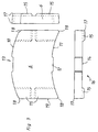
- Figure 1 shows a schematic diagram of the profile of a vehicle light room 1, wherein area 2 defines the contour of a rail vehicle. Is recognizable for example, a platform 3, rails 4 and one, for example from Concrete base layer 5, on which the rails 4 over in this Figure not shown rail fastenings are attached. Between the rails 4 sound absorption elements 6 are arranged. In the same Further, designed as edge elements can be Sound absorption elements 7 are provided next to the rails 4.
- Figure 2 shows a plan view of the route 8. The following can be seen Components according to FIG. 1:
- the base layer 5 the runways 4, inner sound absorption elements 6 and outer sound absorption elements 7 designed as edge elements.
- the runways 4 are on the base layer 5 by means of rail fastenings 9 attached.
- the inner sound absorption elements 6 are of this type dimensioned that their width is less than the inner distance of individual Rail fasteners 9 so that easy access to the Rails 4 and their rail fastenings 9 is given. Repairs can therefore be carried out at any time without removing individual Sound absorption elements 6 and 7 are performed. However, even if the sound absorption elements 6, 7 cover the rail fastenings 9 easy access to the substructure is possible because of the sound absorption elements 6.7 rest only loosely.
- the outer contour of the sound absorption elements is 6.7 so provided that, seen in the longitudinal direction of the rail 4, each other opposite end faces 10, 11 of each sound absorption element 6.7 are rounded, the end face 10 is convex and End face 11 are concavely curved.
- the individual sound absorption elements 6.7 are close together and due to their geometric Front face design 10, 11 easily in the course of the curve of the route 8 and can also be installed in the area of switches. So that the individual Sound absorption elements 6 cannot slip, they become the same positively, horizontally and with little play.
- 6.7 approaches 12 or Recesses 13 are provided, each approach 12 in one corresponding recess 13 of an adjacent one Sound absorption element 6.7 engages.
- each sound absorption element 6, 7 In, facing away from the base layer 5, are not visible area 14 of each sound absorption element 6, 7, a predeterminable distance between underside 14 and base layer 5 generating profiles 15 are provided, whereby below the Sound absorption elements 6.7 so-called reverberation rooms are formed are also conducive to the outflow of water and one Can form a habitat for amphibians.
- the profiles 15 can be made of the same material as that Sound absorption elements 6.7 and be made in one piece with them. she can also consist of a different, elastic material, whereby Unevenness in the road can be compensated better.
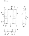
- Figures 3 and 4 show the formed as a molded body Sound absorption elements 6 and 7 in different views. recognizable are the convex or concave shaped end faces 10, 11, the lugs 12 and the recesses 13 and the profiles 15 for generating the distance between the underside 14 and the base layer 5 (not visible here) for formation of so-called reverberation rooms 16.
- the edges 17 of the sound absorption elements 6,7 are chamfered in these examples, while the transitions 18 of the curved end faces 10, 11 are rounded in the rectilinear areas 19, 20 are trained.
- the sound absorption elements 6 and 7 can more, for example be built up in two layers. For example, from an upper narrow-pored and a lower coarse pore layer.
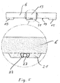
- FIG. 5 shows an alternative embodiment of a sound absorption element 6 or 7.
- this sound absorption element are in the middle in the area of Approach 12 and the recess 13 feet 21 attached, in which Rail direction extending in grooves snap springs 22 are introduced.
- On in the rail direction pipe 23 or other longitudinal element can in the respective snap spring 22 are pressed in and forms a Snap connection.
- This connection via a tube 23 or other Longitudinal element leads to an excellent longitudinal composite Sound absorption elements 6, 7.
- the tube 23 or the other longitudinal element, which interacts with the snap spring 22, is attached at least locally to the base layer 5. This will over the tube 23 or the other longitudinal element the sound absorption elements 6, 7 connected to the base layer 5.
- the snap connection described above still allows easy assembly and disassembly of the Sound absorption elements 6, 7.
- cables or line conductors can be connected to the Sound absorption elements 6, 7 are connected. It is also possible to lay such cables or line conductors freely in the reverberation room 16 without that this with the base layer 5 or the sound absorption elements 6, 7th are connected.
Landscapes
- Engineering & Computer Science (AREA)
- Architecture (AREA)
- Civil Engineering (AREA)
- Structural Engineering (AREA)
- Railway Tracks (AREA)
Abstract
Description
- Hoher Absorptionsgrad in allen Frequenzbereichen.
- Bessere Offenporigkeit bei zweischichtigem Materialaufbau.
- Die verwendeten Ausgangsmaterialien sind ausschließlich ökologischen Ursprungs und somit einhundertprozentig recyclebar.
- Frost- und Tausalzbeständigkeit.
- Die Gesamtstruktur ist widerstandsfähig gegen mechanische und chemische Einflüsse.
- Der Absorptionsbelag ist durch seine feste und dauerhafte Struktur wartungs- und instandhaltungsfrei.
- Die Hochporigkeit der Struktur leitet das Regenwasser schnell und dauerhaft ab, wobei beim Wasserdurchfluß durch die Hohlräume durch den Selbstreinigungseffekt die Schallabsorptionselemente automatisch gereinigt werden.
- Das durch das Schallabsorptionselement hindurchgeflossene Wasser kann ungehindert auf die, insbesondere aus Beton bestehende Tragschicht (Fahrbahn) abfließen.
- Das verwendete Material ist temperaturbeständig und unbrennbar.
- Durch die an sich bekannten Ausnehmungen an der Unterseite der Schallabsorptionselemente wird erreicht, daß sich ein Lebensraum für Amphibien bildet und in einfacher Weise Kabel und/oder Linienleiter verlegt werden können.
- Die Schallabsorptionselemente sind beständig z.B. gegenüber Mineralölen, Fäkalien, Herbiziden, Pestiziden, Fungiziden usw.
- Infolge der festen Struktur werden keine Teilchen herausgelöst, die die Oberfläche der Fahrschienen negativ beeinflussen könnten oder vom überfahrenden Zug hochgewirbelt werden.
- Figur 1
- Querschnitt durch ein Lichtraumprofil;
- Figur 2
- Draufsicht auf in Figur 1 erkennbare Schallabsorptionselemente;
- Figur 3
- Ansicht eines zwischen Fahrschienen verlegbaren Schallabsorptionselementes;
- Figur 4
- Ansicht eines neben einer Fahrschiene verlegbaren Schallabsorptionselementes;
- Figur 5
- Ansicht gemäß Figur 3.
- 1
- Fahrzeuglichtraum
- 2
- Kontur eines Schienenfahrzeuges
- 3
- Bahnsteig
- 4
- Fahrschienen
- 5
- Tragschicht
- 6,7
- Schallabsorptionselemente
- 8
- Fahrstrecke
- 9
- Schienenbefestigung
- 10,11
- Stirnflächen
- 12
- Ansatz
- 13
- Ausnehmung
- 14
- nicht sichtbarer Bereich (Unterseite)
- 15
- Profil
- 16
- Hallraum
- 17
- Kante
- 18
- Übergang
- 19,20
- geradliniger Bereich
- 21
- Fuß
- 22
- Schnappfeder
- 23
- Rohr
Claims (28)
- Schallgedämmter schotterloser Gleisoberbau für Schienenfahrzeuge mit einer Fahrschienen (4) aufnehmenden Tragschicht (5), die zumindest im Bereich der Fahrschienen (4) mit witterungsbeständigen Schallabsorptionselementen (6,7) belegt ist, dadurch gekennzeichnet, daß die Schallabsorptionselemente (6,7) zumindest im Bereich ihrer einander zugewandten, insbesondere quer zur Schienenlängsrichtung verlaufenden Flächen (10,11) gerundete Konturen aufweisen und, daß neben- und/oder hintereinander angeordnete Schallabsorptionselemente (6,7) miteinander verbunden sind.
- Gleisoberbau nach Anspruch 1, dadurch gekennzeichnet, daß die einander gegenüberliegenden Flächen, insbesondere Stirnflächen (10,11), der einzelnen Schallabsorptionselemente (6,7) mit konkaven und konvexen Konturen versehen sind.
- Gleisoberbau nach Anspruch 1 oder 2, dadurch gekennzeichnet, daß die gerundeten Konturen (10,11) im wesentlichen parallel zueinander verlaufend vorgesehen sind.
- Gleisoberbau nach einem der Ansprüche 1 bis 3, dadurch gekennzeichnet, daß in den gerundeten Bereichen (10,11) der einzelnen Schallabsorptionselemente (6,7) mindestens ein Ansatz (12) und mindestens eine Ausnehmung (13) vorgesehen ist, in welche eine korrespondierende Ausnehmung (13) bzw. ein korrespondierender Ansatz (12) benachbarter Schallabsorptionselemente (6,7) formschlüssig eingreift.
- Gleisoberbau nach einem der Ansprüche 1 bis 4, dadurch gekennzeichnet, daß der Ansatz (12) im konkav geformten Stirnflächenbereich (11) und die Ausnehmung (13) im konvex geformten Stirnflächenbereich (10) der einzelnen Schallabsorptionselemente (6,7) vorgesehen ist.
- Gleisoberbau nach einem der Ansprüche 1 bis 5, dadurch gekennzeichnet, daß die Kanten (17) der Schallabsorptionselemente (6,7) abgefast oder abgerundet ausgebildet sind.
- Gleisoberbau nach einem der Ansprüche 1 bis 6, dadurch gekennzeichnet, daß zumindest einzelne der ansonsten lose auf der Tragschicht (5) verlegten Schallabsorptionselemente (6,7) auf der Tragschicht (5) befestigt sind.
- Gleisoberbau nach einem der Ansprüche 1 bis 7, dadurch gekennzeichnet, daß die Schallabsorptionselemente (6,7) an ihrer Unterseite wenigstens ein Klemmelement, vorzugsweise eine Schnappfeder (22), aufweisen und über diese mit einem in Schienenrichtung verlaufenden Längselement, vorzugsweise einem Rohr (23), verbunden sind.
- Gleisoberbau nach Anspruch 8, dadurch gekennzeichnet, daß das Längselement, vorzugsweise das Rohr (23), wenigstens örtlich mit der Tragschicht (5) verbunden ist.
- Gleisoberbau nach einem der Ansprüche 1 bis 9, dadurch gekennzeichnet, daß die Schallabsorptionselemente (6,7) tragschichtseitig mit sich auf der Tragschicht (5) abstützenden einstückig aus den Schallabsorptionselemente (6,7) herausgeformten Profilen (15) versehen sind.
- Gleisoberbau nach einem der Ansprüche 1 bis 10, dadurch gekennzeichnet, daß die Schallabsorptionselemente (6,7) mehrteillig ausgebildet sind und, daß der der Tragschicht (5) zugewandte Bereich zumindest partiell elastisch ausgebildet ist.
- Gleisoberbau nach einem der Ansprüche 1 bis 11, dadurch gekennzeichnet, daß die formschlüssig miteinander verbundenen Schallabsorptionselemente (6,7) sowohl zwischen als auch neben den Fahrschienen (4) angeordnet sind.
- Gleisoberbau nach einem der Ansprüche 1 bis 12, dadurch gekennzeichnet, daß das Breiten-Längen-Verhältnis, insbesondere der zwischen den Fahrschienen (4) vorgesehenen einzelnen Schallabsorptionselemente (6) zugunsten der Breite ausgelegt ist.
- Gleisoberbau nach einem der Ansprüche 1 bis 13, dadurch gekennzeichnet, daß die Schallabsorptionselemente (6,7) aus Holzbeton, bestehend aus insbesondere in Zement gebundenen dauerhaft mineralisierten Spänen, wie Restholzteilen, gebildet sind.
- Schallabsorptionselement, insbesondere zum Einsatz im schotterlosen Gleisoberbau von Schienenfahrzeugen, bestehend aus einem Formkörper aus witterungsbeständigen Material, dadurch gekennzeichnet, daß der Formkörper (6,7) zumindest im Bereich zweier einander gegenüberliegender Stirnflächen (10,11) mit einer sich von Außenkante (18) zu Außenkante (18) erstreckenden Abrundung (10,11) versehen ist.
- Schallabsorptionselement nach Anspruch 15, dadurch gekennzeichnet, daß die eine Stirnfläche (11) konkav und die andere Stirnfläche (10) konvex ausgebildet ist.
- Schallabsorptionselement nach Anspruch 15 oder 16, dadurch gekennzeichnet, daß im Bereich der Abrundungen (10,11) mindestens eine Ausnehmung (13) und/oder mindestens ein Ansatz (12) vorgesehen ist.
- Schallabsorptionselement nach einem der Ansprüche 15 bis 17, dadurch gekennzeichnet, daß der Ansatz (12) im konkav gekrümmten Stirnflächenbereich (11) vorgesehen ist.
- Schallabsorptionselement nach einem der Ansprüche 15 bis 18, dadurch gekennzeichnet, daß die Ausnehmung (13) im konvex gekrümmten Stirnfächenbereich (10) vorgesehen ist.
- Schallabsorptionselement nach einem der Ansprüche 15 bis 19, dadurch gekennzeichnet, daß ein Ansatz (12) und eine Ausnehmung (13) etwa auf halber Höhe der jeweiligen Stirnfläche (10,11) einander gegenüberliegend angeordnet sind.
- Schallabsorptionselement nach einem der Ansprüche 15 bis 20, dadurch gekennzeichnet, daß die Kanten (17) abgefast bzw. abgerundet sind.
- Schallabsorptionselement nach einem der Ansprüche 15 bis 21, dadurch gekennzeichnet, daß im nicht sichtbaren Bereich (14) des Formkörpers (6,7) einen vorgebbarem Abstand zum Aufnahmebereich, insbesondere einer Tragschicht (5), bildende Profile (15) am Formkörper (6,7) angeformt sind.
- Schallabsorptionselement nach einem der Ansprüche 15 bis 22, dadurch gekennzeichnet, daß die Stirnflächenbereiche (10,11) über Rundungen (18) in etwa geradlinig ausgeführte Bereiche (19,20) überführbar sind.
- Schallabsorptionselement nach einem der Ansprüche 15 bis 23, dadurch gekennzeichnet, daß als Ausgangsmaterial für die Herstellung der Schallabsorptionselemente (6,7) dauerhaft mineralisierte Späne, insbesondere aus selektierten Restholzteilen mit gebranntem Zement und Wasser, einsetzbar ist.
- Schallabsorptionselement nach einem der Ansprüche 15 bis 24, dadurch gekennzeichnet, daß es zwei- oder mehrschichtig aufgebaut ist.
- Schallabsorptionselement nach Anspruch 25, dadurch gekennzeichnet, daß es aus gleichartigem Material besteht.
- Schallabsorptionselement nach Anspruch 25 oder Anspruch 26, dadurch gekennzeichnet, daß die Schichten eine unterschiedliche Porosität aufweisen.
- Schallabsorptionselement nach Anspruch 27, dadurch gekennzeichnet, daß die Porosität der unteren, der Tragschicht (5) zugewandten Schicht größer ist als die der oberen Schicht.
Applications Claiming Priority (2)
| Application Number | Priority Date | Filing Date | Title |
|---|---|---|---|
| DE10033000 | 2000-07-06 | ||
| DE2000133000 DE10033000A1 (de) | 2000-07-06 | 2000-07-06 | Schallgedämmter schotterloser Gleisoberbau für Schienenfahrzeuge sowie Schallabsorptionselement |
Publications (2)
| Publication Number | Publication Date |
|---|---|
| EP1170419A2 true EP1170419A2 (de) | 2002-01-09 |
| EP1170419A3 EP1170419A3 (de) | 2002-10-02 |
Family
ID=7648094
Family Applications (1)
| Application Number | Title | Priority Date | Filing Date |
|---|---|---|---|
| EP01116434A Withdrawn EP1170419A3 (de) | 2000-07-06 | 2001-07-06 | Schallgedämmter, schotterloser Gleisoberbau sowie Schallabsorptionselement |
Country Status (2)
| Country | Link |
|---|---|
| EP (1) | EP1170419A3 (de) |
| DE (1) | DE10033000A1 (de) |
Cited By (3)
| Publication number | Priority date | Publication date | Assignee | Title |
|---|---|---|---|---|
| EP1229167A3 (de) * | 2001-02-01 | 2003-05-14 | National Traffic Safety and Environment Laboratory | Schalldämpfender Aufbau für Eisenbahngleise |
| CN102587231A (zh) * | 2011-01-17 | 2012-07-18 | 张洪德 | 无渣轨道道床吸声板安装方法 |
| CN104005308A (zh) * | 2013-12-20 | 2014-08-27 | 柳州汉西鸣建材发展有限公司 | 吸音板 |
Citations (1)
| Publication number | Priority date | Publication date | Assignee | Title |
|---|---|---|---|---|
| DE2729248A1 (de) | 1977-06-29 | 1979-01-04 | Zueblin Ag | Schallgedaemmter, schotterloser gleisoberbau |
Family Cites Families (11)
| Publication number | Priority date | Publication date | Assignee | Title |
|---|---|---|---|---|
| ATE54688T1 (de) * | 1985-11-15 | 1990-08-15 | Ruhl Joh Chr Bauunternehmung | Verbundplattenelement fuer spurbahnen und verfahren zu dessen verlegung. |
| DE3933413A1 (de) * | 1989-10-06 | 1991-04-11 | Sf Vollverbundstein | Pflasterstein, verfahren zu dessen herstellung und fertigungsanlage zur durchfuehrung des verfahrens, vorzugsweise ein betonpflasterstein, insbesondere zur pflasterung einer strasse |
| AT405423B (de) * | 1991-02-08 | 1999-08-25 | Porr Allg Bauges | Oberbau, insbesondere schotterloser oberbau |
| US5186574A (en) * | 1992-02-10 | 1993-02-16 | Tavares Wayne R | Interlocking ground slab element and method |
| DE4417402A1 (de) * | 1994-05-18 | 1995-11-23 | Gruenzweig & Hartmann Montage | Schallschutzeinrichtung zur Schalldämpfung und -dämmung an Gleiskörpern |
| EP0771907A1 (de) * | 1995-11-06 | 1997-05-07 | Vossloh-Werke GmbH | Absorptionskörper zur Luftschallreduzierung |
| DE19543668C2 (de) * | 1995-11-23 | 1999-06-24 | Goepfert Reinhard | Pflasterstein für Verkehrswege |
| DE29601095U1 (de) * | 1996-01-23 | 1997-05-22 | Heilit + Woerner Bau-AG, 81677 München | Schallabsorptionselement |
| DE19635788A1 (de) * | 1996-09-04 | 1998-03-05 | Hermann Kirchner Gmbh & Co Kg | Schalldämpfungselement für Schienentrassen mit fester Fahrbahn |
| DE19812481C2 (de) * | 1998-03-21 | 2002-08-22 | Johann Rath | Vorrichtung zur Dämpfung von Schallemissionen an Gleisanlagen |
| DE19931048A1 (de) * | 1999-07-06 | 2001-02-01 | Bahnbau Wels Gmbh Wels | Gleis für schienengebundene Fahrzeuge sowie Schallschutzelement hierfür |
-
2000
- 2000-07-06 DE DE2000133000 patent/DE10033000A1/de not_active Withdrawn
-
2001
- 2001-07-06 EP EP01116434A patent/EP1170419A3/de not_active Withdrawn
Patent Citations (1)
| Publication number | Priority date | Publication date | Assignee | Title |
|---|---|---|---|---|
| DE2729248A1 (de) | 1977-06-29 | 1979-01-04 | Zueblin Ag | Schallgedaemmter, schotterloser gleisoberbau |
Cited By (3)
| Publication number | Priority date | Publication date | Assignee | Title |
|---|---|---|---|---|
| EP1229167A3 (de) * | 2001-02-01 | 2003-05-14 | National Traffic Safety and Environment Laboratory | Schalldämpfender Aufbau für Eisenbahngleise |
| CN102587231A (zh) * | 2011-01-17 | 2012-07-18 | 张洪德 | 无渣轨道道床吸声板安装方法 |
| CN104005308A (zh) * | 2013-12-20 | 2014-08-27 | 柳州汉西鸣建材发展有限公司 | 吸音板 |
Also Published As
| Publication number | Publication date |
|---|---|
| EP1170419A3 (de) | 2002-10-02 |
| DE10033000A1 (de) | 2002-01-17 |
Similar Documents
| Publication | Publication Date | Title |
|---|---|---|
| EP0901536B1 (de) | Schallschutzeinrichtung für gleise | |
| EP0937181B1 (de) | Unterbau für ein gleis für schienenfahrzeuge | |
| DE4442497A1 (de) | Schotterloses Oberbausystem für zumindest ein Eisenbahngleis | |
| EP2817457B1 (de) | Lärmschutzvorrichtung | |
| DE9417008U1 (de) | Schallreduktionselement für feste Fahrbahn | |
| DE3602313A1 (de) | Schallabsorbierender laermschutz insbesondere fuer schotterlose gleise | |
| EP0767275B1 (de) | Schallabsorber für einen schotterlosen Eisenbahnoberbau | |
| DE29810176U1 (de) | Tunnelfahrweg | |
| CH657648A5 (de) | Schotterloser oberbau fuer schienenbahnen. | |
| DE19706708C2 (de) | Vorrichtung zur Schalldämpfung einer festen Fahrbahn | |
| EP1170419A2 (de) | Schallgedämmter, schotterloser Gleisoberbau sowie Schallabsorptionselement | |
| AT404147B (de) | Schallschutzwand zur dämmung von schallemissionen von verkehrsmitteln | |
| EP2817456B1 (de) | Lärmschutzvorrichtung | |
| DE19643533C2 (de) | Begehbare und/oder befahrbare Abdeckung für Gleise mit Schallschutzelementen | |
| DE3544481A1 (de) | Schallschutzwand und dafuer geeignetes wandelement | |
| EP1258563A2 (de) | Feste Fahrbahn mit elastisch aufgelagerten Schallabsorberelementen | |
| DE202011052057U1 (de) | Lärmschutzvorrichtung | |
| EP0771907A1 (de) | Absorptionskörper zur Luftschallreduzierung | |
| DE19635788A1 (de) | Schalldämpfungselement für Schienentrassen mit fester Fahrbahn | |
| EP1253245A1 (de) | Verfahren zur anderweitigen Nutzung von Gleisen | |
| DE19957223A1 (de) | Plattenschwelle | |
| AT375699B (de) | Schienenanordnung, insbesondere fuer strassenbahn- gleise | |
| DE29905550U1 (de) | Absorptionsbelag zur Reduzierung der Schallabstrahlung für Gleiskörper | |
| DE19921216C2 (de) | Schallabsorptionselement für Schienenstrecken | |
| DE10016105A1 (de) | Gleis für Schienenfahrzeuge insbesondere in fester Fahrbahn |
Legal Events
| Date | Code | Title | Description |
|---|---|---|---|
| PUAI | Public reference made under article 153(3) epc to a published international application that has entered the european phase |
Free format text: ORIGINAL CODE: 0009012 |
|
| AK | Designated contracting states |
Kind code of ref document: A2 Designated state(s): AT BE CH CY DE DK ES FI FR GB GR IE IT LI LU MC NL PT SE TR |
|
| AX | Request for extension of the european patent |
Free format text: AL;LT;LV;MK;RO;SI |
|
| PUAL | Search report despatched |
Free format text: ORIGINAL CODE: 0009013 |
|
| AK | Designated contracting states |
Kind code of ref document: A3 Designated state(s): AT BE CH CY DE DK ES FI FR GB GR IE IT LI LU MC NL PT SE TR |
|
| AX | Request for extension of the european patent |
Free format text: AL;LT;LV;MK;RO;SI |
|
| 17P | Request for examination filed |
Effective date: 20030402 |
|
| AKX | Designation fees paid |
Designated state(s): BE FR GB NL |
|
| 17Q | First examination report despatched |
Effective date: 20030515 |
|
| REG | Reference to a national code |
Ref country code: DE Ref legal event code: 8566 |
|
| STAA | Information on the status of an ep patent application or granted ep patent |
Free format text: STATUS: THE APPLICATION HAS BEEN WITHDRAWN |
|
| 18W | Application withdrawn |
Effective date: 20030906 |