EP1170729A2 - Schwimmender Kopf mit Gleitkörper und Aufzeichnungs/Wiedergabegerät mit solchem Kopf - Google Patents
Schwimmender Kopf mit Gleitkörper und Aufzeichnungs/Wiedergabegerät mit solchem Kopf Download PDFInfo
- Publication number
- EP1170729A2 EP1170729A2 EP01305780A EP01305780A EP1170729A2 EP 1170729 A2 EP1170729 A2 EP 1170729A2 EP 01305780 A EP01305780 A EP 01305780A EP 01305780 A EP01305780 A EP 01305780A EP 1170729 A2 EP1170729 A2 EP 1170729A2
- Authority
- EP
- European Patent Office
- Prior art keywords
- recording
- floating
- head slider
- slider
- rail plane
- Prior art date
- Legal status (The legal status is an assumption and is not a legal conclusion. Google has not performed a legal analysis and makes no representation as to the accuracy of the status listed.)
- Withdrawn
Links
Images







Classifications
-
- G—PHYSICS
- G11—INFORMATION STORAGE
- G11B—INFORMATION STORAGE BASED ON RELATIVE MOVEMENT BETWEEN RECORD CARRIER AND TRANSDUCER
- G11B5/00—Recording by magnetisation or demagnetisation of a record carrier; Reproducing by magnetic means; Record carriers therefor
- G11B5/48—Disposition or mounting of heads or head supports relative to record carriers ; arrangements of heads, e.g. for scanning the record carrier to increase the relative speed
- G11B5/58—Disposition or mounting of heads or head supports relative to record carriers ; arrangements of heads, e.g. for scanning the record carrier to increase the relative speed with provision for moving the head for the purpose of maintaining alignment of the head relative to the record carrier during transducing operation, e.g. to compensate for surface irregularities of the latter or for track following
- G11B5/60—Fluid-dynamic spacing of heads from record-carriers
- G11B5/6005—Specially adapted for spacing from a rotating disc using a fluid cushion
-
- G—PHYSICS
- G11—INFORMATION STORAGE
- G11B—INFORMATION STORAGE BASED ON RELATIVE MOVEMENT BETWEEN RECORD CARRIER AND TRANSDUCER
- G11B21/00—Head arrangements not specific to the method of recording or reproducing
- G11B21/16—Supporting the heads; Supporting the sockets for plug-in heads
- G11B21/20—Supporting the heads; Supporting the sockets for plug-in heads while the head is in operative position but stationary or permitting minor movements to follow irregularities in surface of record carrier
- G11B21/21—Supporting the heads; Supporting the sockets for plug-in heads while the head is in operative position but stationary or permitting minor movements to follow irregularities in surface of record carrier with provision for maintaining desired spacing of head from record carrier, e.g. fluid-dynamic spacing, slider
Definitions
- the present invention relates to a floating-type head slider which is, for example, provided in a magnetic recording/reproducing apparatus and configured to have a magnetic head float over a surface of a recording medium at the time of driving, and a recording/reproducing apparatus having such a head slider.
- a floating-type slider having an air bearing surface (air lubricating surface) is provided for a magnetic head so as to ensure a predetermined gap between the magnetic head and a magnetic disk by means of an air pressure at the time of disk rotation, which results in information recording in a non-contact manner.
- Fig. 13 of the accompanying drawings is a perspective view showing a general slider 100 viewed from underneath.
- the slider 100 is arranged to have rails 101a, 101b each having an air bearing surface (air lubricating surface), and a magnetic head 102 is fixed at an end surface of the rail 101b.
- an airflow generated when a magnetic disk 103 is rotated produces a floating power (pressure) onto the rails 101a and 101b.
- the floating power makes the slider 100 and the magnetic head 102 float above a surface of the magnetic disk 103 with a slight gap (flying height) therebetween.
- a hard disk device of a floating head type as described above, even in a case of a disk having unevenness on a surface thereof, it is possible to reduce a spacing loss by making the magnetic head follow the unevenness on the surface. In addition, it is possible to prevent a magnetic head from contacting with a surface a magnetic disk so as to prevent the magnetic disk from wear and damage.
- the flying height of the slider is significantly minute. Accordingly, even in a case where a quite small amount of dust comes into the hard disk device, there may be caused a serious damage to the hard disk device. Therefore, it is a usual manner that a hard disk device is assembled in a highly controlled clean room.
- a hard disk device is required to secure reliability in a case of receiving external vibration and shock, in other words, it is quite important to prevent a slider from contacting with the hard disk.
- the present invention is made in consideration of the above-described problem to be solved and there are provided a floating head slider having high reliability even in an environment to which dust may come into and a recording/reproducing apparatus in which such a floating head slider is employed.
- a floating-type head slider having at least a rail plane which functions as an air bearing in accordance with a kinetic pressure of an air flow caused by rotation of a recording medium, which supports a recording/reproducing device for recording and reproducing information keeping a predetermined gap between the device and a surface of the recording medium, wherein all of or almost all of edges (i.e., rails) of the rail plane comprises only a plurality of straight lines and arcs each being a part of one of an ellipse and a circle, for smoothly connecting ends of two of the straight lines.
- edges i.e., rails
- an edge of the rail plane which is positioned at a same height level is configured to be continuously endless.
- the head slider comprises a plurality of rail planes with a plurality of height levels.
- an area of a rail plane which comes closest to the magnetic disk is 30% or more, more preferably, 40% or more of the entire area, which functions as the air bearing, of the slider.
- the rail plane comprises at least leg portions provided at a center portion and both end portions opposing to a moving direction and a connecting portion provided ahead in the moving direction for connecting among the leg portions.
- the rail plane has a comb-like shape.
- a recording/reproducing device having a floating-type head slider having at least a rail plane which functions as an air bearing in accordance with a kinetic pressure of an air flow caused by rotation of a recording medium, which supports a recording/reproducing device for recording and reproducing information keeping a predetermined gap between the device and a surface of the recording medium, wherein an edge of the rail plane comprises only a plurality of straight lines and arcs being a part of an ellipse or a circle, for smoothly connecting ends of two of the straight lines.
- a recording/reproducing device having the floating-type head slider according to the first point of view can be provided.
- a floating-type head slider having high reliability even in an environment into which a dust may come and a recording/reproducing apparatus in which such a floating-type head slider is employed can be provided.
- FIG. 1 is a perspective view showing an example of a configuration of a hard disk device 1 (hard disk drive) built in or externally connected to a computer or the like.
- a hard disk device 1 hard disk drive
- reference numeral 2 shows a housing of the hard disk device 1.
- a spindle motor which is not shown in the figure is installed on a bottom portion of the housing 2.
- a magnetic disk 3 is rotatively driven at a fixed angular velocity by the spindle motor.
- a base end portion 4a of an arm 4 is swingably held at a corner of the housing 2.
- a voice coil motor which is not shown in the figure is connected to a base end portion 4a of the arm 4, and swingably drives a tip portion 4b of the arm 4 along a top surface of the magnetic disk 3.
- the slider 6 of the present embodiment is held at the tip portion 4b of the arm 4 via a suspension 5.
- the suspension 5 comprises a spring portion 7 fixed on the side of the base end portion 4a of the arm 4, and a gimbal 8 and a pivot 9 for connecting the slider 6 to the spring portion 7.
- the slider 6 has a function of ensuring a predetermined gap (flying height) between the slider 6 and the magnetic disk 3 by keeping a balance between a downward load applied by the suspension 5 and an upward floating power generated by the air pressure due to the rotation of the magnetic disk 3.
- a magnetic head 10 is fixed at a rear end plane of the slider 6.
- the arm 4 is swingably driven when a predetermined voltage is applied to the voice coil motor. According thereto, the magnetic head 10 fixed to the slider 6 moves along a substantially radial direction of the magnetic disk 3, in other word, the slider 6 carries out a seeking operation, so as to record or reproduce information on or from a predetermined track of the magnetic disk 3.
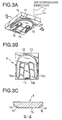
- Fig. 3A is a perspective view of the slider 6 viewed from underneath;
- Fig. 3B is a plan view of the slider 6;
- Fig. 3C is a longitudinal cross-sectional view of the slider 6 cut along the line III-III.
- the slider 6 has a first rail 12 and a second rail 13.
- a rail means an edge of a rail plane.
- a first rail plane 15, a second rail plane 16 and a third rail plane 17 each having different height level are constituted.
- All of the first and second rails 12 and 13 comprises of straight lines and arcs each being a part of ellipses or circles to connect these straight lines smoothly, having an endless shape which are not segmented along the way.
- an air introducing end 11 of the first and second rails 12 and 13 has a single-peaked shape.
- the slider 6 is configured so that an area of the first rail plane 15 occupies more than 40% of the total area of the first, second and third rail planes 15-17.
- the first rail plane 15 is formed to be a ctenoid, i.e., comb-like shape having three leg portions 15a-15c, and these three leg portions are mutually connected at a front side of the moving direction to be unified. According to such construction, there are formed negative pressure pockets 18 and 19 between the leg portions 15a and 15b and between the leg portions 15b and 15c, respectively.
- the magnetic head 10 is fixed to a rear end portion along a moving direction of the leg portion 15b which is positioned at the center of the slider 6.
- the slider 6 is designed to utilize a positive pressure in a direction away from the magnetic disk 3 and a negative pressure in a direction toward the magnetic disk 3 so as to have a predetermined gap (flying height) between the magnetic disk 3 and the slider 6 keeping the difference between the positive pressure and the negative pressure and the load applied by the suspension in balance.
- the area of the first rail plane 15 is relatively large in comparison with the other rail planes 16 and 17, the first rail plane 15 receives most of the above-mentioned positive pressure. Accordingly, in comparison with a conventional slider, it is possible with the slider 6 of the present invention to reduce the load per unit area on the rail plane closest to the magnetic disk 3.
- the first rail plane 15 which is positioned at the highest level comes into contact with the magnetic disk 3 in such a case.
- the contact pressure with the magnetic disk 3 becomes small, as a result. This brings an effect that the magnetic disk 3 receives less damage.
- the rail plane is also formed in the leg portion 15b positioned at the center of the first rail plane 15 and all rails are formed endlessly with a plurality of straight lines and arcs each being a part of an ellipse and a circle for connecting end portions of one of the straight lines and another straight line smoothly, the magnetic disk 3 is less damaged.
- the air bearing surface of the slider 6 is generally processed so that the center portion thereof has a convex shape, that is, so-called “crown", toward the magnetic disk in comparison with the both edge portions.
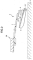
- a pad-type rail plane having processed to have a "crown” approaches the magnetic disk, as shown in Fig. 10, an edge portion 20 of a divided rail plane first comes into contact with the magnetic disk 3 geometrically, which results in a strong possibility of damage of the magnetic disk by a sharp edge of the rail plane.
- the slider 6 of the present embodiment has the leg portion 15b at a center portion thereof and all rails are formed continuously. Furthermore, since there are formed the negative pressure pockets 18 and 19 between the leg portions 15a and 15b and leg portions 15b and 15c, respectively, a resistance force against the negative pressure improves. Accordingly, the problem mentioned above hardly occurs, and possibility to damage the disk with an edge of the rail becomes low.
- the slider 6 of the present embodiment is effective in preventing the magnetic disk from being damages.
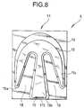
- the present embodiment has been described with reference to FIGS. 3A to 3C, however, it is also possible to utilize a slider having a shape as shown in FIGs. 4 to 9, for example.
- a tip portion (to which the magnetic head is attached) of the leg portion 15b has a larger area.
- each of the leg portions 15a and 15c has a narrower tip portion.
- FIGs. 6 to 9 show modified examples in which the area of the bottom 115 of the leg portion 15b are varied, respectively.
- the rails are formed with straight lines and arcs for connecting ends of the straight lines in every embodiment.
- the rail is constituted to be endless with continuity, and the rail plane has a single peak toward an air introducing end.
- the first slider is a slider having pad-type rail planes (as shown in FIG. 11)
- the second and the third sliders are those according to the present invention (as shown in FIGs. 3A to 3C).
- a ratio of the first rail for the total area of the air bearing surface of the slider in each of the first to third sliders is 15.2%, 34.4% and 41.9%, respectively.
- All sliders are in size of 1.25 ⁇ 1.0 ⁇ 0.3mm, and application load thereto by a suspension is 3.0gf.
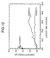
- the comparing test is conducted such that the three kinds of sliders are floated for a long time in a controlled dust existing atmosphere so as to measure a contact force between the slider and the disk, at regular intervals. Results of the comparing test are shown in FIG. 12.
- the contact force rises first in the conventional pad-type slider (that is shown in FIG. 11), and next, one of the sliders of the present invention, whose area ratio of the first rail plane is 34.4%, and subsequently, the other one whose area ratio being 41.9%.
- a slider of the present invention is more superior to a conventional slider.
- an acceleration coefficient of this experimental test is about 1000 times in view of another experimental test, and thus, the durability of 40 hours or more in this experimental test is required-to guarantee a durability of five years or more of the slider being used in a device.
- the contact force rises sharply in the conventional slider, and the rails and the disk were damaged in a short time during the experimental test, quality of product level cannot be guaranteed.
- an area ratio of the first rail plane toward the air bearing surface of the slider it becomes possible to guarantee reliability of product level by setting an area ratio of the first rail plane toward the air bearing surface of the slider to be 30% or more, more preferably, an area ratio of 40% or more further improves the durability.
- the recording/reproducing apparatus is a hard disk device, however, the recording/reproducing apparatus is not limited to this case.
- the present invention may be applied even to a floppy disk recording/reproducing apparatus or the like only if the apparatus employs a floating type head slider.
- the floating type slider described above may be a near-contact type.
Landscapes
- Adjustment Of The Magnetic Head Position Track Following On Tapes (AREA)
- Supporting Of Heads In Record-Carrier Devices (AREA)
Applications Claiming Priority (4)
| Application Number | Priority Date | Filing Date | Title |
|---|---|---|---|
| JP2000202218 | 2000-07-04 | ||
| JP2000202218 | 2000-07-04 | ||
| JP2001080572 | 2001-03-21 | ||
| JP2001080572A JP2002083477A (ja) | 2000-07-04 | 2001-03-21 | 浮動型ヘッドスライダおよびそれを利用する記録/再生装置 |
Publications (2)
| Publication Number | Publication Date |
|---|---|
| EP1170729A2 true EP1170729A2 (de) | 2002-01-09 |
| EP1170729A3 EP1170729A3 (de) | 2003-01-22 |
Family
ID=26595341
Family Applications (1)
| Application Number | Title | Priority Date | Filing Date |
|---|---|---|---|
| EP01305780A Withdrawn EP1170729A3 (de) | 2000-07-04 | 2001-07-04 | Schwimmender Kopf mit Gleitkörper und Aufzeichnungs/Wiedergabegerät mit solchem Kopf |
Country Status (7)
| Country | Link |
|---|---|
| US (1) | US6603638B2 (de) |
| EP (1) | EP1170729A3 (de) |
| JP (1) | JP2002083477A (de) |
| KR (1) | KR20020004851A (de) |
| CN (1) | CN1190791C (de) |
| SG (1) | SG102629A1 (de) |
| TW (1) | TW543031B (de) |
Families Citing this family (11)
| Publication number | Priority date | Publication date | Assignee | Title |
|---|---|---|---|---|
| US8535382B2 (en) | 2000-04-10 | 2013-09-17 | Biomet Manufacturing, Llc | Modular radial head prostheses |
| US8114163B2 (en) | 2000-04-10 | 2012-02-14 | Biomet Manufacturing Corp. | Method and apparatus for adjusting height and angle for a radial head |
| US8920509B2 (en) | 2000-04-10 | 2014-12-30 | Biomet Manufacturing, Llc | Modular radial head prosthesis |
| US7012785B2 (en) * | 2002-10-07 | 2006-03-14 | Samsung Electronics Co., Ltd. | Method and apparatus for head slider and suspension reducing air flow turbulence about the slider when accessing a rotating disk in a disk drive |
| US20040070111A1 (en) * | 2002-10-09 | 2004-04-15 | Chen-Chou Hsieh | Zipper and method of making zipper composition |
| JP2004164685A (ja) * | 2002-11-08 | 2004-06-10 | Sony Corp | 浮上ヘッドスライダおよびこれを用いたディスク記憶装置 |
| JP3889374B2 (ja) * | 2003-04-10 | 2007-03-07 | アルプス電気株式会社 | 磁気ヘッド装置および前記磁気ヘッド装置を用いた磁気ディスク装置 |
| JP4095580B2 (ja) | 2004-06-07 | 2008-06-04 | 株式会社東芝 | ヘッドアクチュエータアッセンブリの製造方法およびディスク装置の製造方法 |
| US20070025023A1 (en) * | 2005-07-26 | 2007-02-01 | Hitachi Global Storage Technologies Netherlands B.V. | Magnetic head slider with suppressed flying height reduction and magnetic hard disk drive |
| US20070297080A1 (en) * | 2006-06-23 | 2007-12-27 | Lee Sungchang | Apparatus and method for bending a slider to create rounded corners on its trailing edge in a hard disk drive |
| JP2008059642A (ja) * | 2006-08-29 | 2008-03-13 | Fujitsu Ltd | ヘッドスライダおよび記憶媒体駆動装置 |
Family Cites Families (11)
| Publication number | Priority date | Publication date | Assignee | Title |
|---|---|---|---|---|
| US4555739A (en) | 1982-11-26 | 1985-11-26 | International Business Machines Corporation | Semi self-loading ferrite head |
| JP3108514B2 (ja) | 1992-03-13 | 2000-11-13 | ティーディーケイ株式会社 | 薄膜磁気ヘッドの製造方法 |
| US5430591A (en) | 1992-10-13 | 1995-07-04 | Hitachi, Ltd. | Negative pressure flying head slider having siderails with narrow width portion |
| JP3243698B2 (ja) | 1993-05-19 | 2002-01-07 | 株式会社日立製作所 | 負圧利用浮動ヘッドスライダ及び回転円板記憶装置 |
| JP3251359B2 (ja) | 1993-01-19 | 2002-01-28 | 株式会社日立製作所 | 磁気ヘッドスライダおよび磁気記憶装置 |
| JPH0737352A (ja) | 1993-07-19 | 1995-02-07 | Tdk Corp | 浮上型磁気ヘッドスライダ |
| US5654853A (en) * | 1994-02-04 | 1997-08-05 | Seagate Technology, Inc. | Disc storage device having a magnetic head air bearing slider configuration for reduced disc overhead |
| JP2895031B2 (ja) | 1997-09-29 | 1999-05-24 | 茨城日本電気株式会社 | 浮動型磁気ヘッドスライダおよびこれを用いた磁気ディスク装置 |
| JPH11238213A (ja) | 1998-02-24 | 1999-08-31 | Hitachi Metals Ltd | 空気潤滑面を持った磁気ヘッド |
| US6483667B1 (en) * | 1998-07-21 | 2002-11-19 | Seagate Technology Llc | Self-loading disc head slider having multiple steps approximating a leading taper |
| US6144528A (en) * | 1998-10-26 | 2000-11-07 | Read-Rite Corporation | Air bearing slider with reduced stiction |
-
2001
- 2001-03-21 JP JP2001080572A patent/JP2002083477A/ja active Pending
- 2001-06-28 TW TW090115800A patent/TW543031B/zh not_active IP Right Cessation
- 2001-06-29 US US09/896,475 patent/US6603638B2/en not_active Expired - Lifetime
- 2001-07-02 KR KR1020010039338A patent/KR20020004851A/ko not_active Abandoned
- 2001-07-04 CN CNB011221305A patent/CN1190791C/zh not_active Expired - Fee Related
- 2001-07-04 EP EP01305780A patent/EP1170729A3/de not_active Withdrawn
- 2001-07-04 SG SG200104037A patent/SG102629A1/en unknown
Also Published As
| Publication number | Publication date |
|---|---|
| SG102629A1 (en) | 2004-03-26 |
| JP2002083477A (ja) | 2002-03-22 |
| TW543031B (en) | 2003-07-21 |
| EP1170729A3 (de) | 2003-01-22 |
| US20020071217A1 (en) | 2002-06-13 |
| US6603638B2 (en) | 2003-08-05 |
| CN1337703A (zh) | 2002-02-27 |
| KR20020004851A (ko) | 2002-01-16 |
| CN1190791C (zh) | 2005-02-23 |
Similar Documents
| Publication | Publication Date | Title |
|---|---|---|
| KR0145029B1 (ko) | 자기 기록 디스크 드라이브 및 변환기 조립체 | |
| KR970006867B1 (ko) | 공기 베어링 슬라이더 | |
| KR100407845B1 (ko) | 디스크 저장 장치용 슬라이더 | |
| KR100524943B1 (ko) | 디스크 드라이브의 공기 베어링 슬라이더 | |
| US7515384B2 (en) | Method and apparatus for providing a three stepped air bearing having a funnel structure for controlling air flow to improve fly height performance | |
| US6128163A (en) | Disk drive including slider with recessed magneto-resistive transducer | |
| US5663853A (en) | Head slider assembly having first and second leading edge tapered portions formed on lower and upper surfaces of an air inflow edge | |
| WO2001029827A3 (en) | Air bearing slider with reduced stiction | |
| US6603638B2 (en) | Floating-type head slider and recording/reproducing apparatus employing the same | |
| EP0747890A1 (de) | Gleitkörper mit Mittelschiene zur Nahaufzeichnung | |
| KR20010030264A (ko) | 가요성 디스크용 자기 헤드 슬라이더 | |
| US6459547B1 (en) | Slider with pads and textured landing zone for disc storage system | |
| US20050231852A1 (en) | Slider for high density magnetic recording | |
| EP0793229B1 (de) | Oberflächenmerkmale auf luftkissengelagerter Oberfläche zur Optimierung des Wandlerabstands | |
| US6181519B1 (en) | Tri-pad air bearing head slider having leading edge and trailing edge of air bearing side pads tapered to minimize takeoff and landing velocity and time | |
| US20040075947A1 (en) | Head slider | |
| US5668682A (en) | Head lift mechanism implemented in a removable magnetic disk drive | |
| US6879463B2 (en) | Head slider and disk drive unit employing the same | |
| US4891721A (en) | Magnetic head device | |
| JP3064634B2 (ja) | ディスクドライブ装置 | |
| US20060082927A1 (en) | Head, head suspension assembly, and disk device provided with the same | |
| US20060132978A1 (en) | Slider for high density magnetic recording | |
| JP2001167418A (ja) | ヘッドスライダ及びディスクドライブ装置 | |
| JP3175249B2 (ja) | 浮上ヘッド支持機構及び浮上ヘッド装置 | |
| KR100392670B1 (ko) | 하드디스크드라이브의헤드장치 |
Legal Events
| Date | Code | Title | Description |
|---|---|---|---|
| PUAI | Public reference made under article 153(3) epc to a published international application that has entered the european phase |
Free format text: ORIGINAL CODE: 0009012 |
|
| AK | Designated contracting states |
Kind code of ref document: A2 Designated state(s): AT BE CH CY DE DK ES FI FR GB GR IE IT LI LU MC NL PT SE TR |
|
| AX | Request for extension of the european patent |
Free format text: AL;LT;LV;MK;RO;SI |
|
| PUAL | Search report despatched |
Free format text: ORIGINAL CODE: 0009013 |
|
| AK | Designated contracting states |
Kind code of ref document: A3 Designated state(s): AT BE CH CY DE DK ES FI FR GB GR IE IT LI LU MC NL PT SE TR |
|
| AX | Request for extension of the european patent |
Free format text: AL;LT;LV;MK;RO;SI |
|
| 17P | Request for examination filed |
Effective date: 20030610 |
|
| AKX | Designation fees paid |
Designated state(s): DE FR GB |
|
| 17Q | First examination report despatched |
Effective date: 20071011 |
|
| STAA | Information on the status of an ep patent application or granted ep patent |
Free format text: STATUS: THE APPLICATION IS DEEMED TO BE WITHDRAWN |
|
| 18D | Application deemed to be withdrawn |
Effective date: 20080222 |