EP1170821A2 - Dispositif d'antenne - Google Patents
Dispositif d'antenne Download PDFInfo
- Publication number
- EP1170821A2 EP1170821A2 EP01305583A EP01305583A EP1170821A2 EP 1170821 A2 EP1170821 A2 EP 1170821A2 EP 01305583 A EP01305583 A EP 01305583A EP 01305583 A EP01305583 A EP 01305583A EP 1170821 A2 EP1170821 A2 EP 1170821A2
- Authority
- EP
- European Patent Office
- Prior art keywords
- antenna
- radio communication
- conductive plate
- ground conductor
- portable radio
- Prior art date
- Legal status (The legal status is an assumption and is not a legal conclusion. Google has not performed a legal analysis and makes no representation as to the accuracy of the status listed.)
- Withdrawn
Links
Images
Classifications
-
- H—ELECTRICITY
- H01—ELECTRIC ELEMENTS
- H01Q—ANTENNAS, i.e. RADIO AERIALS
- H01Q1/00—Details of, or arrangements associated with, antennas
- H01Q1/12—Supports; Mounting means
- H01Q1/22—Supports; Mounting means by structural association with other equipment or articles
- H01Q1/24—Supports; Mounting means by structural association with other equipment or articles with receiving set
- H01Q1/241—Supports; Mounting means by structural association with other equipment or articles with receiving set used in mobile communications, e.g. GSM
- H01Q1/242—Supports; Mounting means by structural association with other equipment or articles with receiving set used in mobile communications, e.g. GSM specially adapted for hand-held use
- H01Q1/245—Supports; Mounting means by structural association with other equipment or articles with receiving set used in mobile communications, e.g. GSM specially adapted for hand-held use with means for shaping the antenna pattern, e.g. in order to protect user against rf exposure
-
- H—ELECTRICITY
- H01—ELECTRIC ELEMENTS
- H01Q—ANTENNAS, i.e. RADIO AERIALS
- H01Q1/00—Details of, or arrangements associated with, antennas
- H01Q1/52—Means for reducing coupling between antennas; Means for reducing coupling between an antenna and another structure
- H01Q1/526—Electromagnetic shields
Definitions
- the present invention relates to an antenna device which may be a portable radio communication device, and particularly to an antenna device capable of reducing electromagnetic waves which are generated therefrom and are to be absorbed into a human body.
- portable data transmitting/receiving devices capable of transmitting/receiving information by radio communication are significantly developed.
- portable radio communication devices for use in the PHS (Personal Handyphone System) system are spreading rapidly.
- the portable radio communication device usually has an antenna for transmitting/receiving signals.
- the portable radio communication device itself works as an antenna, and the main body of the portable radio communication device other than the antenna portion also generates electromagnetic waves. So, it is required that, of the electromagnetic waves generated from the portable radio communication device, those to be absorbed into a human body should be suppressed.
- amount of electromagnetic waves to be absorbed into a specific portion of a human body, particularly a head portion, per unit-time per unit-weight is defined as local average SAR (Specific Absorption Rate), and the maximum value of the local average SAR is required to be not more than a prescribed value.
- SAR Specific Absorption Rate
- a conductive plate of a predetermined shape may be used.
- the conductive plate has its one end connected to a ground conductor which works as an antenna to form a short circuit, and has its other end electrically released from the ground conductor.
- input impedance of the electrically released end becomes approximately infinite. At this time, high-frequency current flowing to the ground conductor is suppressed, and thus amount of radiation of the electromagnetic waves is reduced.
- Fig.1 shows a schematic view of a portable radio communication device 20, which can reduce the maximum value of the local average SAR.
- the portable radio communication device 20 includes a circuit board (not shown) necessary for performing radio communication, shield case 21 as a ground conductor which shields the circuit board, a conductive plate 22, an antenna feeding portion 23, and an antenna 24.
- the circuit board, shield case 21, and conductive plate 22 are enclosed by a housing (not shown) made of nonconductive material.
- the conductive plate 22 and shield case 21 are connected by a conductor 25 to form a short circuit.
- circuits including a transmitting/receiving circuit for communicating with a base station which are mounted on the circuit board do not have bad effects upon each other, and also do not have bad effects upon the antenna 24 and other devices.
- the transmitting/receiving circuit on the circuit board in the shield case 21 generates transmission signals of a predetermined signal form, and sends the transmission signals to the antenna 24 via the antenna feeding portion 23. Then, the antenna 24 transmits the transmission signals to the base station. The antenna 24 receives reception signals from the base station, and sends the reception signals to the transmitting/receiving circuit via the antenna feeding portion 23. Then, the transmitting/receiving circuit performs processing for the reception signals such as demodulating.
- the antenna 24 is a rod antenna made of conductive wire materials, or a helical antenna made of conductive wire materials wound spirally. Otherwise, the antenna 24 may be an antenna of various types such as a stretch type antenna combining the rod antenna and helical antenna.
- the portable radio communication device 20 performs radio communication, since the high-frequency current flows to the shield case 21 via the antenna feeding portion 23, not only the antenna 24 but also the shield case 21 as a ground conductor for the circuit board works as an antenna. That is, whole the portable radio communication device 20 works as an antenna.
- the user comes into contact with a speaker of the portable radio communication device 20.
- the shield case 21 as a ground conductor for the circuit board located behind the speaker also works as an antenna and radiates electromagnetic waves, there will be formed a portion where the value of the local average SAR becomes maximum around an ear of the user which comes into contact with the speaker, and this portion will be referred to as a hot spot.
- the portable radio communication device 20 has the conductive plate 22 arranged such that the speaker (not shown) faces the conductive plate 22, and the conductive plate 22 and a front surface 21a of the shield case 21 are approximately parallel with each other with a slight interval therebetween.
- the interval between the conductive plate 22 and the front surface 21a of the shield case 21 depends on a radio communication frequency, and the portable radio communication device 20 can adjust the frequency bandwidth in accordance with the interval.
- the conductive plate 22 has its one end along the longitudinal direction connected to the shield case 21 to form a short circuit via the conductor 25, and has its other end electrically released from the shield case 21.
- the length L3 between the short circuit forming end and the electrically released end is set to be a quarter of the radio communication frequency.
- the impedance between the conductive plate 22 and the shield case 21 becomes close to zero at the short circuit forming end, while becoming approximately infinite at the electrically released end.
- the high-frequency current has difficulty in flowing from the antenna feeding portion 23 to the conductive plate 22 and the shield case 21.
- the portable radio communication device 20 mounts a conductive plate 22 thereto, and reduces the amount of radiation of the electromagnetic waves from the conductive plate 22 and shield case 21.
- the local average SAR of the hot spot can be reduced.
- an antenna device having an antenna element and a ground conductor which work as an antenna, in which the antenna element is fed via an antenna feeding portion and high-frequency current flows to the ground conductor via the antenna feeding portion, the antenna device including: high-frequency current suppressing means being a conductive plate of a predetermined shape which has its both ends along one direction electrically opened from the ground conductor.
- a portable radio communication device which has an antenna device having an antenna element and a ground conductor which work as an antenna, in which the antenna element is fed via an antenna feeding portion and high-frequency current flows to the ground conductor via the antenna feeding portion,
- the longitudinal length of the conductive plate is an integer multiple of half a wavelength at the frequency of the radio communication.
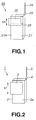
- Fig.1 shows a schematic view of a conductive plate mounted to the conventional portable radio communication device.
- Fig.2 shows a schematic view of a conductive plate mounted to a first embodiment of the portable radio communication device according to the present invention.
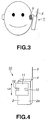
- Fig.3 shows a schematic view of a portion where the value of the local average SAR of the electromagnetic waves generated from the first and second embodiments of the portable radio communication device according to the present invention in use becomes maximum.
- Fig.4 shows a schematic view of a conductive plate mounted to a second embodiment of the portable radio communication device according to the present invention.
- the portable radio communication device has mounted thereto a conductive plate whose longitudinal length is set to be half the radio communication frequency.
- Fig.2 shows a schematic view of a first embodiment of a portable radio communication device 1 according to the present invention.
- the portable radio communication device 1 includes a circuit board (not shown) necessary for performing radio communication, shield case 2 as a ground conductor which shields the circuit board, a conductive plate 3, an antenna feeding portion 4, and an antenna 5.
- the circuit board, shield case 2, and conductive plate 3 are enclosed by a housing (not shown) made of nonconductive material.
- circuits including a transmitting/receiving circuit for communicating with a base station which are mounted on the circuit board do not have bad effects upon each other, and also do not have bad effects upon the antenna 5 and other devices.
- the transmitting/receiving circuit on the circuit board in the shield case 2 generates transmission signals of a predetermined signal form, and sends the transmission signals to the antenna 5 via the antenna feeding portion 4. Then, the antenna 5 transmits the transmission signals to the base station.
- the antenna 5 receives reception signals from the base station, and sends the reception signals to the transmitting/receiving circuit via the antenna feeding portion 4. Then, the transmitting/receiving circuit performs processing for the reception signals such as demodulating.
- the antenna 5 is a rod antenna made of conductive wire materials.
- the portable radio communication device 1 performs radio communication, since the high-frequency current flows to the shield case 2 via the antenna feeding portion 4, not only the antenna 5 but also the shield case 2 as a ground conductor for the circuit board works as an antenna. That is, whole the portable radio communication device 1 works as an antenna.
- the portable radio communication device 1 itself works as an antenna, and the main body of the portable radio communication device 1 other than the antenna 5 portion generates electromagnetic waves. So, it is required that electromagnetic waves to be absorbed into a human body should be suppressed. Specifically, of the electromagnetic waves generated from the portable radio communication device 1, amount of electromagnetic waves to be absorbed into a specific portion of a human body, particularly a head portion, per unit-time per unit-weight is defined as local average SAR (Specific Absorption Rate), and the maximum value of the local average SAR is required to be not more than a prescribed value.
- SAR Specific Absorption Rate
- the portable radio communication device 1 When the portable radio communication device 1 is used, the user comes into contact with a speaker, not shown, of the portable radio communication device 1, as schematically shown in Fig.3. Since the shield case 2 as a ground conductor for the circuit board located behind the speaker also works as an antenna and radiates electromagnetic waves, there will be formed a portion where the value of the local average SAR becomes maximum around an ear of the user which comes into contact with the speaker, and this portion will be referred to as a hot spot 6.
- the portable radio communication device 1 has the conductive plate 3 arranged such that the speaker (not shown) faces the conductive plate 3, and the conductive plate 3 and a front surface 2a of the shield case 2 are approximately parallel with each other with an appropriate interval therebetween, as shown in Fig.2.
- the conductive plate 3 is different from the conductive plate 22 of the portable radio communication device 20.
- the conductive plate 3 is not connected to the shield case 2, and has its both ends along the longitudinal direction electrically released from the shield case 2.
- the length L1 between the both electrically released ends of the conductive plate 3 is set to be half the radio communication frequency.
- the impedance between the shield case 2 and the conductive plate 3 becomes approximately infinite at the both electrically released ends, while becoming close to zero at around the center portion of the conductive plate 3.
- the conductive plate 3 is not connected to the shield case 2 and does not form a short circuit, since the impedance increases at the both electrically released ends, the high-frequency current has difficulty in flowing from the antenna feeding portion 4 to the conductive plate 3 and shield case 2.
- the radiation of the electromagnetic waves from the conductive plate 3 and shield case 2 at the time of using the portable radio communication device 1 is reduced, and the maximum value of the local average SAR of the hot spot 6 is reduced.
- the interval between the conductive plate 3 and the front surface 2a of the shield case 2 depends on a radio communication frequency, and the portable radio communication device 1 can adjust the interval in accordance with the frequency bandwidth.
- the interval between the conductive plate 3 and the front surface 2a of the shield case 2 can easily be changed by inserting a spacer corresponding to a predetermined interval therebetween.
- the conductive plate 3 may be formed by applying a metal plating to the corresponding inner part of the housing which encloses the shield case 2.
- Fig.4 shows a schematic view of a second embodiment of a portable radio communication device 10 according to the present invention.
- the basic configuration of the portable radio communication device 10 is similar to that of the portable radio communication device 1 shown in Fig.2.
- the parts or components similar to those of the portable radio communication device 1 are indicated with the same reference numerals.
- the portable radio communication device 10 includes a conductive plate 11 which also is not connected to the shield case 2, and has its both ends along the longitudinal direction electrically released from the shield case 2.
- the conductive plate 11 has two slits 12 at predetermined positions, as shown in Fig.4.
- the length L2 between the both electrically released ends of the conductive plate 11 can be set shorter than the length L1 of the portable radio communication device 1 by providing the slits 12.
- the slits 12 are provided such that the electrical length of the conductive plate 11 becomes half the radio communication frequency.
- the positions where the slits 12 are provided are not restricted to those shown in Fig.4.
- the configuration, depth and widths of the slits 12 are not restricted to those shown in Fig.4.
- the slits 12 may be an opening slit which is provided by cutting off a predetermined shape from the conductive plate 11.
- the portable radio communication devices 1, 10 are not provided with anything between the front surface 2a of the shield case 2 and conductive plates 3, 11.
- the portable radio communication devices 1, 10 may have inserted therein a dielectric having a predetermined relative dielectric constant between the front surface 2a of the shield case 2 and conductive plates 3, 11.
- the lengths L1, L2 between the both electrically released ends of the conductive plates 3, 11 can be set shorter due to wavelength-reducing effect corresponding to the relative dielectric constant of the dielectric.
- the length L between the both electrically released ends satisfy the following equation 1, in which ⁇ represents a wavelength used in the radio communication and ⁇ represents the relative dielectric constant of the dielectric.
- L ⁇ 2 ⁇ 1 ⁇
- the lengths L1, L2 between the both electrically released ends of the conductive plates 3, 11 can be set shorter, which can reduce the portable radio communication devices 1, 10 in size.
- the antenna 5 is connected to the transmitting/receiving circuit.
- the antenna 5 may be connected to a transmitting circuit.
- the conductive plates 3 and 11 are of a rectangular shape.
- the present invention is not restricted as such.
- the conductive plate 3 of any shape can be used and similar effect can be obtained as long as the electrical lengths of the conductive plates 3 and 11 become half the radio communication frequency.
- the conductive plates 3 and 11 may be made of transparent or translucent conductive material and may be arranged on a front surface of a liquid crystal display.
- an antenna device having an antenna element and a ground conductor which work as an antenna, in which the antenna element is fed via an antenna feeding portion and high-frequency current flows to the ground conductor via the antenna feeding portion.
- the antenna device includes high-frequency current suppressing means which is a conductive plate of a predetermined shape which has its both ends along one direction electrically released from the ground conductor.
- the longitudinal length of the conductive plate is an integer multiple of half a wavelength at the frequency of the radio communication.
- Such an antenna device can reduce the electromagnetic waves to be absorbed into a human body without forming a short circuit between the conductive plate and the ground conductor. Also, since the number of parts is reduced, it becomes possible to reduce production cost.
- a portable radio communication device which has an antenna device having an antenna element and a ground conductor which work as an antenna, in which the antenna element is fed via an antenna feeding portion and high-frequency current flows to the ground conductor via the antenna feeding portion.
- a circuit board for transmitting/receiving signals is shielded by the ground conductor.
- the antenna device includes high-frequency current suppressing means which is a conductive plate of a predetermined shape which has its both ends along one direction electrically released from the ground conductor.
- the longitudinal length of the conductive plate is an integer multiple of half a wavelength at the frequency of the radio communication.
- Such a portable radio communication device can reduce the electromagnetic waves to be absorbed into a human body without forming a short circuit between the conductive plate and the ground conductor. Also, since the number of parts is reduced, it becomes possible to reduce production cost.
Landscapes
- Physics & Mathematics (AREA)
- Electromagnetism (AREA)
- Engineering & Computer Science (AREA)
- Computer Networks & Wireless Communication (AREA)
- Support Of Aerials (AREA)
- Transceivers (AREA)
- Details Of Aerials (AREA)
- Telephone Set Structure (AREA)
Applications Claiming Priority (2)
| Application Number | Priority Date | Filing Date | Title |
|---|---|---|---|
| JP2000204329A JP2002026627A (ja) | 2000-07-05 | 2000-07-05 | アンテナ装置及び携帯型無線端末 |
| JP2000204329 | 2000-07-05 |
Publications (2)
| Publication Number | Publication Date |
|---|---|
| EP1170821A2 true EP1170821A2 (fr) | 2002-01-09 |
| EP1170821A3 EP1170821A3 (fr) | 2002-10-09 |
Family
ID=18701605
Family Applications (1)
| Application Number | Title | Priority Date | Filing Date |
|---|---|---|---|
| EP01305583A Withdrawn EP1170821A3 (fr) | 2000-07-05 | 2001-06-28 | Dispositif d'antenne |
Country Status (5)
| Country | Link |
|---|---|
| US (1) | US6469670B2 (fr) |
| EP (1) | EP1170821A3 (fr) |
| JP (1) | JP2002026627A (fr) |
| KR (1) | KR20020004838A (fr) |
| CN (1) | CN1337761A (fr) |
Cited By (1)
| Publication number | Priority date | Publication date | Assignee | Title |
|---|---|---|---|---|
| WO2008152180A1 (fr) * | 2007-06-14 | 2008-12-18 | Elektrobit Wireless Communications Oy | Structure d'antenne interne de téléphone portable |
Families Citing this family (14)
| Publication number | Priority date | Publication date | Assignee | Title |
|---|---|---|---|---|
| JP3838815B2 (ja) * | 1999-05-10 | 2006-10-25 | 日本電気株式会社 | 携帯電話機 |
| KR20040000535A (ko) * | 2002-06-21 | 2004-01-07 | (주)컴뮤웍스 | 이동 통신 단말기의 내장형 gps안테나 |
| US20040198264A1 (en) * | 2002-08-22 | 2004-10-07 | Ben Saur | Telephone radiation shielding devices |
| AU2003268957A1 (en) * | 2002-12-19 | 2004-07-14 | Jose Luis De La Torre Barreiro | Passive reflector for a mobile communication device |
| JP2004363392A (ja) * | 2003-06-05 | 2004-12-24 | Hitachi Ltd | プリント配線基板および無線通信装置 |
| KR100625121B1 (ko) * | 2003-07-01 | 2006-09-19 | 에스케이 텔레콤주식회사 | 통신핸드셋 장치에서의 sar 노출 감소 방법 및 장치 |
| DE10339900A1 (de) * | 2003-08-29 | 2005-04-07 | Siemens Ag | Mobiles Kommunikationsgerät |
| JP4312100B2 (ja) * | 2003-11-18 | 2009-08-12 | ソニー・エリクソン・モバイルコミュニケーションズ株式会社 | 携帯通信端末 |
| CN100403865C (zh) * | 2004-01-05 | 2008-07-16 | 英华达(上海)电子有限公司 | 无线通讯装置中的电路板及其制造方法 |
| JP2007006267A (ja) * | 2005-06-24 | 2007-01-11 | Matsushita Electric Ind Co Ltd | 携帯無線機器及び折畳式携帯無線機器 |
| US9160070B2 (en) * | 2010-02-16 | 2015-10-13 | William N. Carr | Radiation-hardened RFID tags |
| JP5802704B2 (ja) | 2013-06-13 | 2015-10-28 | 株式会社ソニー・コンピュータエンタテインメント | アンテナ装置およびそれを用いた電子機器 |
| TWI540790B (zh) * | 2013-09-27 | 2016-07-01 | 佳世達科技股份有限公司 | 天線裝置及應用其之通訊裝置 |
| CN108123212B (zh) * | 2016-11-29 | 2020-06-02 | 北京小米移动软件有限公司 | 控制终端天线系统辐射的方法、装置以及天线系统 |
Citations (2)
| Publication number | Priority date | Publication date | Assignee | Title |
|---|---|---|---|---|
| US5764190A (en) * | 1996-07-15 | 1998-06-09 | The Hong Kong University Of Science & Technology | Capacitively loaded PIFA |
| JP2000101333A (ja) * | 1998-09-21 | 2000-04-07 | Sony Corp | アンテナ装置及び携帯無線装置 |
Family Cites Families (11)
| Publication number | Priority date | Publication date | Assignee | Title |
|---|---|---|---|---|
| US4965408A (en) * | 1989-02-01 | 1990-10-23 | Borden, Inc. | Composite sheet material for electromagnetic radiation shielding |
| US5826201A (en) * | 1992-11-25 | 1998-10-20 | Asterion, Inc. | Antenna microwave shield for cellular telephone |
| FR2699773A1 (fr) * | 1992-12-17 | 1994-06-24 | Alsthom Cge Alcatel | Emetteur radio portable. |
| US6259896B1 (en) * | 1994-02-15 | 2001-07-10 | Nokia Mobile Phones Limited | Device for radio communication |
| US5530919A (en) * | 1993-10-12 | 1996-06-25 | Murata Manufacturing Co., Ltd. | Mobile communicator with means for attenuating transmitted output toward the user |
| GB2302474B (en) * | 1995-10-27 | 1997-06-11 | Leslie Ronald Wilson | Improvements in or relating to a shielding device |
| SE508365C2 (sv) * | 1996-11-04 | 1998-09-28 | Ericsson Telefon Ab L M | Radiotelefon med hög antenneffektivitet |
| IT1304350B1 (it) * | 1998-03-12 | 2001-03-15 | Diego Balestra | Sistema di telecomunicazione per piccole e medie citta' medianteradiofonia mobile con protezione dell'utente. |
| US6326924B1 (en) * | 1998-05-19 | 2001-12-04 | Kokusai Electric Co., Ltd. | Polarization diversity antenna system for cellular telephone |
| JP2000165126A (ja) * | 1998-11-30 | 2000-06-16 | Matsushita Electric Ind Co Ltd | アンテナ装置 |
| US6157546A (en) * | 1999-03-26 | 2000-12-05 | Ericsson Inc. | Shielding apparatus for electronic devices |
-
2000
- 2000-07-05 JP JP2000204329A patent/JP2002026627A/ja active Pending
-
2001
- 2001-06-28 EP EP01305583A patent/EP1170821A3/fr not_active Withdrawn
- 2001-06-29 KR KR1020010038057A patent/KR20020004838A/ko not_active Withdrawn
- 2001-07-03 US US09/898,145 patent/US6469670B2/en not_active Expired - Fee Related
- 2001-07-05 CN CN01122406A patent/CN1337761A/zh active Pending
Patent Citations (2)
| Publication number | Priority date | Publication date | Assignee | Title |
|---|---|---|---|---|
| US5764190A (en) * | 1996-07-15 | 1998-06-09 | The Hong Kong University Of Science & Technology | Capacitively loaded PIFA |
| JP2000101333A (ja) * | 1998-09-21 | 2000-04-07 | Sony Corp | アンテナ装置及び携帯無線装置 |
Cited By (1)
| Publication number | Priority date | Publication date | Assignee | Title |
|---|---|---|---|---|
| WO2008152180A1 (fr) * | 2007-06-14 | 2008-12-18 | Elektrobit Wireless Communications Oy | Structure d'antenne interne de téléphone portable |
Also Published As
| Publication number | Publication date |
|---|---|
| KR20020004838A (ko) | 2002-01-16 |
| JP2002026627A (ja) | 2002-01-25 |
| EP1170821A3 (fr) | 2002-10-09 |
| CN1337761A (zh) | 2002-02-27 |
| US6469670B2 (en) | 2002-10-22 |
| US20020014994A1 (en) | 2002-02-07 |
Similar Documents
| Publication | Publication Date | Title |
|---|---|---|
| US6947000B2 (en) | Antenna device and portable radio communication device | |
| EP1170821A2 (fr) | Dispositif d'antenne | |
| US4800392A (en) | Integral laminar antenna and radio housing | |
| US5539414A (en) | Folded dipole microstrip antenna | |
| US4571595A (en) | Dual band transceiver antenna | |
| US6031495A (en) | Antenna system for reducing specific absorption rates | |
| TW469667B (en) | Dual band diversity antenna having parasitic radiating element | |
| US6016126A (en) | Non-protruding dual-band antenna for communications device | |
| US6933897B2 (en) | Mobile communications antenna and transceiving apparatus | |
| EP0757405A1 (fr) | Antenne | |
| DE60218056T2 (de) | Drahtloses funkgerät | |
| KR970063822A (ko) | 표면실장형 안테나 및 이 안테나를 사용하는 통신기기 | |
| WO2006002090A1 (fr) | Antenes elliptiques differentielles et asymetriques | |
| EP1152481B1 (fr) | Dispositif d'antenne et appareil de communiation sans fil portable | |
| KR100371875B1 (ko) | 상이한개구모양을갖는평면및비-평면더블시-패치안테나 | |
| CN210723338U (zh) | 可穿戴设备 | |
| CN112736471A (zh) | 天线及电子设备 | |
| US6876332B1 (en) | Multiple-frequency antenna structure | |
| US6041220A (en) | Portable radio communication apparatus | |
| CN113555679B (zh) | 天线单元和电子设备 | |
| WO2001093367A1 (fr) | Terminal portable sans fil | |
| KR100861882B1 (ko) | 다중대역 안테나 | |
| JP2002299945A (ja) | マイクロストリップアンテナ | |
| KR100531624B1 (ko) | 초광대역 역 l형 안테나 장치 | |
| CN112886199B (zh) | 一种四合一天线组件及平板电脑 |
Legal Events
| Date | Code | Title | Description |
|---|---|---|---|
| PUAI | Public reference made under article 153(3) epc to a published international application that has entered the european phase |
Free format text: ORIGINAL CODE: 0009012 |
|
| AK | Designated contracting states |
Kind code of ref document: A2 Designated state(s): AT BE CH CY DE DK ES FI FR GB GR IE IT LI LU MC NL PT SE TR |
|
| AX | Request for extension of the european patent |
Free format text: AL;LT;LV;MK;RO;SI |
|
| PUAL | Search report despatched |
Free format text: ORIGINAL CODE: 0009013 |
|
| AK | Designated contracting states |
Kind code of ref document: A3 Designated state(s): AT BE CH CY DE DK ES FI FR GB GR IE IT LI LU MC NL PT SE TR |
|
| AX | Request for extension of the european patent |
Free format text: AL;LT;LV;MK;RO;SI |
|
| 17P | Request for examination filed |
Effective date: 20030312 |
|
| AKX | Designation fees paid |
Designated state(s): DE FR GB |
|
| 17Q | First examination report despatched |
Effective date: 20031030 |
|
| STAA | Information on the status of an ep patent application or granted ep patent |
Free format text: STATUS: THE APPLICATION IS DEEMED TO BE WITHDRAWN |
|
| 18D | Application deemed to be withdrawn |
Effective date: 20040414 |