EP1170822B1 - Adapteur d'antenne pour un telephone portable - Google Patents
Adapteur d'antenne pour un telephone portable Download PDFInfo
- Publication number
- EP1170822B1 EP1170822B1 EP01850119A EP01850119A EP1170822B1 EP 1170822 B1 EP1170822 B1 EP 1170822B1 EP 01850119 A EP01850119 A EP 01850119A EP 01850119 A EP01850119 A EP 01850119A EP 1170822 B1 EP1170822 B1 EP 1170822B1
- Authority
- EP
- European Patent Office
- Prior art keywords
- antenna
- adapter
- adapter antenna
- conductive
- condenser plate
- Prior art date
- Legal status (The legal status is an assumption and is not a legal conclusion. Google has not performed a legal analysis and makes no representation as to the accuracy of the status listed.)
- Expired - Lifetime
Links
Images



Classifications
-
- H—ELECTRICITY
- H01—ELECTRIC ELEMENTS
- H01Q—ANTENNAS, i.e. RADIO AERIALS
- H01Q1/00—Details of, or arrangements associated with, antennas
- H01Q1/12—Supports; Mounting means
- H01Q1/22—Supports; Mounting means by structural association with other equipment or articles
- H01Q1/24—Supports; Mounting means by structural association with other equipment or articles with receiving set
- H01Q1/241—Supports; Mounting means by structural association with other equipment or articles with receiving set used in mobile communications, e.g. GSM
- H01Q1/242—Supports; Mounting means by structural association with other equipment or articles with receiving set used in mobile communications, e.g. GSM specially adapted for hand-held use
-
- H—ELECTRICITY
- H01—ELECTRIC ELEMENTS
- H01Q—ANTENNAS, i.e. RADIO AERIALS
- H01Q1/00—Details of, or arrangements associated with, antennas
- H01Q1/27—Adaptation for use in or on movable bodies
- H01Q1/32—Adaptation for use in or on road or rail vehicles
- H01Q1/325—Adaptation for use in or on road or rail vehicles characterised by the location of the antenna on the vehicle
-
- H—ELECTRICITY
- H01—ELECTRIC ELEMENTS
- H01Q—ANTENNAS, i.e. RADIO AERIALS
- H01Q9/00—Electrically-short antennas having dimensions not more than twice the operating wavelength and consisting of conductive active radiating elements
- H01Q9/04—Resonant antennas
- H01Q9/0407—Substantially flat resonant element parallel to ground plane, e.g. patch antenna
- H01Q9/0421—Substantially flat resonant element parallel to ground plane, e.g. patch antenna with a shorting wall or a shorting pin at one end of the element
-
- H—ELECTRICITY
- H04—ELECTRIC COMMUNICATION TECHNIQUE
- H04B—TRANSMISSION
- H04B1/00—Details of transmission systems, not covered by a single one of groups H04B3/00 - H04B13/00; Details of transmission systems not characterised by the medium used for transmission
- H04B1/38—Transceivers, i.e. devices in which transmitter and receiver form a structural unit and in which at least one part is used for functions of transmitting and receiving
- H04B1/3827—Portable transceivers
- H04B1/3877—Arrangements for enabling portable transceivers to be used in a fixed position, e.g. cradles or boosters
Definitions
- the invention concerns an adapter antenna which without contact can receive and transfer an electromagnatic wave within the near field of another antenna.
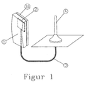
- the most common application of an adapter antenna is for connection of a mobile telephone which temporarily is used within a vehicle to an external antenna located on the outside of the vehicle.
- All mobile telephones are provided with a built-on first antenna, but not all models are provided with a coaxial outlet for connection to an external second antenna. If one wishes to use an external antenna with a mobile telephone lacking such an antenna outlet, an adapter antenna can be located near the first antenna and connected by a coaxial cable (33) to the second antenna.
- Antennae are usually located in the far field of a first antenna, where the wave front is approximatively flat with the electric and magnetic field vectors at right angles to each other. In this case, the antennae do not influence the current distribution of each other, and they may be designed independently of each other.
- An adapter antenna is located close to a first antenna in the near field of this. The electric and magnetic field vectors are here generally not at right angles to each other. The current distributions of the first antenna and the adapter antenna will influence each other.
- the transfer between the first antenna and the adapter antenna should be total, and all power from the first antenna should be collected by the adapter antenna, which in practise can never be acheived.
- the non-transferred power will radiate into the vehicle. This is a great disadvantage, the radiation has not fully recognized biological effects which were the reason for deciding to use an external antenna.
- These decribed conditions which are specific for adapter antenna compared to other types of antennae, mean that adapter antennae should be individually optimized for each type of first antenna. The optimizing may be more difficult if the telephone is of multiple N-band type, where N is larger than 1.
- Adapter antella for such are known in from patents US 422095, GB 2266997, SE 50393U, US 577585, SE 504343, WO98/25323. These all use a coil as a coupling element.
- Adapter antennae suitable also for other types of telephone antennae can be shaped as meander convolutions as described in patents SE 506726 and SE 507100.
- the document D1 EP-A-0 999 607 discloses an antenna coupler for coupling a radio telecommunication device with an integral planar antenna to an external device.
- the intergral planar antenna of the radio telecommunication device comprises a first planar conductive antenna element.
- the antenna coupler comprises a second planar conductive antenna element which is essentially similar to the first planar conductive antenna element, a first conductive ground plane parallel to said second planar conductive antenna element and transmission means for conducting a radio frequency signal between said second planar conductive antenna element and the external device.
- the document EP-A-1 006 606, cited by the Examiner, discloses a holder and a method for transferring signals between apparatus and holder.
- the invention relates to a holder for a handheld apparatus for emitting radio signals, said apparatus comprising a patch-antenna.
- the holder comprises a patch antenna which is adapted to cooperate with the corresponding patch antenna on an apparatus placed in the holder.
- adapter antennae are not optimal for certain types of first antennae, such as inverted L, E and F(PIFA) antennae. Coils are less suitable for adapter antennae to these.
- One aim of the invention is to acheive an optimal solution by utilizing the electric field component, implying acting as a condenser together with a suitable adaptive circuit.
- the invention can be used for single as well as multiple frequency band adapter antennae.
- the optimizing is made in the following steps:
- the components of the adapter antenna (2) are located on a circuit board (19,20) with circuit patterns of conductive metal on both sides.
- Alternative embodiments, not shown in a figure, may be circuit boards with conductive pattern on one side only, or metal foil conductors, or plastic boards with conductive surface patterns applied by metallizing, metal spraying, conductive paint or foil.
- the adaptive circuit at the port (32) is also located on the circuit board in the version shown by figures 5 and 6. Other designs of adaptive circuits with discrete or continuous components are commonly known and will not be discussed here.
- FIG 2 shows the PIFA antenna (6) of the mobile telephone (1), comprising a radiator (7) from sheet metal and a ground surface (11).
- the radiator (7) is connected to the mobile telephone electronics at the feed point (9) and forms a stub with a ground connection (10).
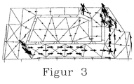
- the current distribution while transmitting in the 900 MHz band is shown in figure 3 and in the 1800 MHz band in figure 4.
- the condenser plate (21) is located on the first side (19) of the circuit board, which is closest to the mobile telephone (1) when this is placed near the adapter antenna (2).
- the condenser plate (21) has two horns (22 and 23) of conductive material, covering the high current density regions close to the feed point (9) and the stub (10) of the PIFA antenna (6). In another embodiment not shown here, separate but electrically connected plates are located over the high current regions.
- the conductor (24) is located above the slot (8) so as not to be noticably influenced by the currents in the antenna (6).
- the ground plane of the adapter antenna is located, comprising a ground plane island (28) and a ground plane loop (29).
- a transfer (25) consisting of a coplanar waveguide (26) comprising a solder island (27) and ground plane islands (30 and 31), as well as a condenser towards ground, comprising a solder island (27) and a ground plane island (28).
- This condenser will compensate the inductance of the conductor (24).
- the transfer (25) provides adapting to a 50 ohm coaxial cable.
- the other end (3) of the coaxial cable may be connected to a second antenna (4) or to an amplifier unit not shown in the figure.
- Currents in the shield (34) of the coaxial cable (33) can be suppressed by means of a quarter wave trap (35). For use with several frequency bands, several wave traps may be supplied. Another possibility is to use a loss means, such as a ferrite ring, to extinguish any wave that could follow the outside of the shield.
- Optimizing the dimensions of the pattern should be made in such a way that not only provides a good transmission from the PIFA antenna (6) to the adapter antenna (2) as well as in the other direction, but also fulfills the demand that the impedance of the PIFA antenna in the feed point (9) should be influenced as little as possible.
Landscapes
- Engineering & Computer Science (AREA)
- Computer Networks & Wireless Communication (AREA)
- Remote Sensing (AREA)
- Signal Processing (AREA)
- Waveguide Aerials (AREA)
- Details Of Aerials (AREA)
- Support Of Aerials (AREA)
Claims (12)
- Antenne à adaptateur (2) pour le transfert sans contact d'ondes électromagnétiques dans n bandes de fréquences, avec n ≥ 1, entre une première antenne (6) de type plane en forme de E, F ou L inversé, montée dans un téléphone mobile (1) au moyen d'une plaque de condensateur (21, 22, 23) montée dans l'antenne à adaptateur (2) et un port (32) de l'antenne à adaptateur (2) où un câble coaxial (3) peut être raccordé pour relier l'antenne à adaptateur (2) à une deuxième antenne externe ou à un amplificateur, caractérisée en ce que la plaque de condensateur (21, 22, 23) est parallèle à une surface conductrice de la première antenne (6) et située à proximité de celle-ci, et en ce que la plaque de condensateur (21, 22, 23) présente une forme telle qu'elle recouvre des surfaces proches d'un point d'alimentation (9) et d'une entaille (10) de la première antenne (6) et les zones de la surface en métal rayonnant de la première antenne (6) où les courants de surface sont relativement élevés dans l'une quelconque des n bandes de fréquences, afin d'utiliser principalement la composante électrique du champ proche de la première antenne pour le transfert sans contact.
- Antenne à adaptateur (2) selon la revendication 1, complétée par un plan de masse comprenant un ilôt (28) et une boucle (29) situés en-dehors de la plaque de condensateur (21, 22, 23).
- Antenne à adaptateur (2) selon la revendication 1 ou 2, caractérisée en ce que l'antenne à adaptateur (2) est équipée d'un conducteur (24) qui est situé en regard d'une fente (8) de la première antenne (6) et est raccordé à la plaque de condensateur (21, 22, 23).
- Antenne à adaptateur (2) selon la revendication 1, dans laquelle l'unité d'adaptation, au niveau du port (32), comprend un guide d'ondes (26) coplanaire et un condensateur en direction de la masse (27, 28).
- Antenne à adaptateur (2) selon la revendication 1 ou 4, dans laquelle le plan de masse (28) est équipé, pour accroítre ses dimensions, par des rubans conducteurs (29) ou fils métalliques, ou par des bandes de matériau conducteur suivant les bords du composant (19) qui porte la plaque de condensateur (21).
- Antenne à adaptateur (2) selon les revendications 1, 4 ou 5, dans laquelle les surfaces conductrices sont situées sur un plaque à circuit imprimé.
- Antenne à adaptateur (2) selon les revendications 1, 4, 5 ou 6, dans laquelle les surfaces conductrices sont constituées en tôle.
- Antenne à adaptateur (2) selon l'une des revendications 1 et 4 à 7, dans laquelle les surfaces conductrices sont constituées par métallisation de plastique.
- Antenne à adaptateur (2) selon l'une des revendications 1 et 4 à 8, dans laquelle les surfaces conductrices sont constituées par de la peinture conductrice.
- Antenne à adaptateur (2) selon l'une des revendications 1 et 4 à 9, dans laquelle les surfaces conductrices sont constituées en feuille de métal.
- Antenne à adaptateur (2) selon l'une des revendications 1 et 4 à 10, dans laquelle le câble coaxial (33) est équipé d'un filtre éliminateur (35) qui supprime les courants dans le blindage (34) du cåble.
- Antenne à adaptateur (2) selon l'une des revendications 1 et 4 à 11, dans laquelle le câble coaxial (33) est équipé d'un composant à pertes internes élevées, qui supprime les courants dans le blindage (34) du câble.
Applications Claiming Priority (2)
| Application Number | Priority Date | Filing Date | Title |
|---|---|---|---|
| SE0002575 | 2000-07-07 | ||
| SE0002575A SE523526C2 (sv) | 2000-07-07 | 2000-07-07 | Adapterantenn avsedd att samverka elektromagnetiskt med en antenn inbyggd i en mobiltelefon |
Publications (2)
| Publication Number | Publication Date |
|---|---|
| EP1170822A1 EP1170822A1 (fr) | 2002-01-09 |
| EP1170822B1 true EP1170822B1 (fr) | 2005-04-13 |
Family
ID=20280416
Family Applications (1)
| Application Number | Title | Priority Date | Filing Date |
|---|---|---|---|
| EP01850119A Expired - Lifetime EP1170822B1 (fr) | 2000-07-07 | 2001-07-05 | Adapteur d'antenne pour un telephone portable |
Country Status (4)
| Country | Link |
|---|---|
| US (1) | US6538607B2 (fr) |
| EP (1) | EP1170822B1 (fr) |
| DE (1) | DE60109995T2 (fr) |
| SE (1) | SE523526C2 (fr) |
Cited By (11)
| Publication number | Priority date | Publication date | Assignee | Title |
|---|---|---|---|---|
| US8466756B2 (en) | 2007-04-19 | 2013-06-18 | Pulse Finland Oy | Methods and apparatus for matching an antenna |
| US8473017B2 (en) | 2005-10-14 | 2013-06-25 | Pulse Finland Oy | Adjustable antenna and methods |
| US8564485B2 (en) | 2005-07-25 | 2013-10-22 | Pulse Finland Oy | Adjustable multiband antenna and methods |
| US8618990B2 (en) | 2011-04-13 | 2013-12-31 | Pulse Finland Oy | Wideband antenna and methods |
| US8629813B2 (en) | 2007-08-30 | 2014-01-14 | Pusle Finland Oy | Adjustable multi-band antenna and methods |
| US8648752B2 (en) | 2011-02-11 | 2014-02-11 | Pulse Finland Oy | Chassis-excited antenna apparatus and methods |
| US8786499B2 (en) | 2005-10-03 | 2014-07-22 | Pulse Finland Oy | Multiband antenna system and methods |
| US8847833B2 (en) | 2009-12-29 | 2014-09-30 | Pulse Finland Oy | Loop resonator apparatus and methods for enhanced field control |
| US9406998B2 (en) | 2010-04-21 | 2016-08-02 | Pulse Finland Oy | Distributed multiband antenna and methods |
| US9450291B2 (en) | 2011-07-25 | 2016-09-20 | Pulse Finland Oy | Multiband slot loop antenna apparatus and methods |
| US9673507B2 (en) | 2011-02-11 | 2017-06-06 | Pulse Finland Oy | Chassis-excited antenna apparatus and methods |
Families Citing this family (39)
| Publication number | Priority date | Publication date | Assignee | Title |
|---|---|---|---|---|
| US20010011224A1 (en) * | 1995-06-07 | 2001-08-02 | Stephen James Brown | Modular microprocessor-based health monitoring system |
| SE524825C2 (sv) * | 2001-03-07 | 2004-10-12 | Smarteq Wireless Ab | Antennkopplingsanordning samverkande med en intern första antenn anordnad i en kommunikationsanordning |
| DE10131335A1 (de) * | 2001-06-28 | 2003-01-09 | Bisplinghoff Gisela | Adapter füt einen Telefonhalter einer Freisprecheinrichtung |
| FI115803B (fi) * | 2002-12-02 | 2005-07-15 | Filtronic Lk Oy | Järjestely lisäantennin kytkemiseksi radiolaitteeseen |
| USD488148S1 (en) | 2002-12-23 | 2004-04-06 | Cingular Wireless, Llc | Auxiliary antenna for a fixed antenna handset |
| USD495686S1 (en) | 2003-04-30 | 2004-09-07 | Cingular Wireless, Llc | Auxiliary antenna for an internal antenna handset |
| FI115172B (fi) * | 2003-07-24 | 2005-03-15 | Filtronic Lk Oy | Antennijärjestely ulkoisen laitteen liittämiseksi radiolaitteeseen |
| SE528327C2 (sv) * | 2005-10-10 | 2006-10-17 | Amc Centurion Ab | Antennanordning |
| USD564520S1 (en) * | 2006-02-06 | 2008-03-18 | Microsoft Corporation | Housing for an electronic device |
| US7930814B2 (en) * | 2006-07-26 | 2011-04-26 | Raytheon Company | Manufacturing method for a septum polarizer |
| EP2095464A4 (fr) * | 2006-11-16 | 2012-10-24 | Galtronics Ltd | Antenne compacte |
| CN101217213B (zh) | 2007-12-26 | 2012-05-23 | 蒋小平 | 汽车顶置天线装置 |
| FI20096134A0 (fi) | 2009-11-03 | 2009-11-03 | Pulse Finland Oy | Säädettävä antenni |
| FI20096251A0 (sv) | 2009-11-27 | 2009-11-27 | Pulse Finland Oy | MIMO-antenn |
| DE102011011053A1 (de) | 2010-02-13 | 2011-08-18 | PEIKER acustic GmbH & Co. KG, 61381 | Anordnung zur Ankopplung eines Mobiltelefons an eine externe Antenne |
| FI20105158A7 (fi) | 2010-02-18 | 2011-08-19 | Pulse Finland Oy | Kuorisäteilijällä varustettu antenni |
| JP4875176B2 (ja) * | 2010-02-19 | 2012-02-15 | 株式会社東芝 | アンテナ及びカプラ |
| US8559869B2 (en) | 2011-09-21 | 2013-10-15 | Daniel R. Ash, JR. | Smart channel selective repeater |
| CN103814476B (zh) | 2011-01-03 | 2016-03-16 | 盖尔创尼克股份有限公司 | 紧凑型宽频带天线 |
| FI20115072A0 (fi) | 2011-01-25 | 2011-01-25 | Pulse Finland Oy | Moniresonanssiantenni, -antennimoduuli ja radiolaite |
| US8866689B2 (en) | 2011-07-07 | 2014-10-21 | Pulse Finland Oy | Multi-band antenna and methods for long term evolution wireless system |
| US9123990B2 (en) | 2011-10-07 | 2015-09-01 | Pulse Finland Oy | Multi-feed antenna apparatus and methods |
| US9531058B2 (en) | 2011-12-20 | 2016-12-27 | Pulse Finland Oy | Loosely-coupled radio antenna apparatus and methods |
| US9484619B2 (en) | 2011-12-21 | 2016-11-01 | Pulse Finland Oy | Switchable diversity antenna apparatus and methods |
| US8988296B2 (en) | 2012-04-04 | 2015-03-24 | Pulse Finland Oy | Compact polarized antenna and methods |
| US9979078B2 (en) | 2012-10-25 | 2018-05-22 | Pulse Finland Oy | Modular cell antenna apparatus and methods |
| US10069209B2 (en) | 2012-11-06 | 2018-09-04 | Pulse Finland Oy | Capacitively coupled antenna apparatus and methods |
| US9647338B2 (en) | 2013-03-11 | 2017-05-09 | Pulse Finland Oy | Coupled antenna structure and methods |
| US10079428B2 (en) | 2013-03-11 | 2018-09-18 | Pulse Finland Oy | Coupled antenna structure and methods |
| US9634383B2 (en) | 2013-06-26 | 2017-04-25 | Pulse Finland Oy | Galvanically separated non-interacting antenna sector apparatus and methods |
| US9680212B2 (en) | 2013-11-20 | 2017-06-13 | Pulse Finland Oy | Capacitive grounding methods and apparatus for mobile devices |
| US9590308B2 (en) | 2013-12-03 | 2017-03-07 | Pulse Electronics, Inc. | Reduced surface area antenna apparatus and mobile communications devices incorporating the same |
| US9350081B2 (en) | 2014-01-14 | 2016-05-24 | Pulse Finland Oy | Switchable multi-radiator high band antenna apparatus |
| US9973228B2 (en) | 2014-08-26 | 2018-05-15 | Pulse Finland Oy | Antenna apparatus with an integrated proximity sensor and methods |
| US9948002B2 (en) | 2014-08-26 | 2018-04-17 | Pulse Finland Oy | Antenna apparatus with an integrated proximity sensor and methods |
| US9722308B2 (en) | 2014-08-28 | 2017-08-01 | Pulse Finland Oy | Low passive intermodulation distributed antenna system for multiple-input multiple-output systems and methods of use |
| US9906260B2 (en) | 2015-07-30 | 2018-02-27 | Pulse Finland Oy | Sensor-based closed loop antenna swapping apparatus and methods |
| WO2018126247A2 (fr) | 2017-01-02 | 2018-07-05 | Mojoose, Inc. | Indicateur automatique d'intensité de signal et commutateur automatique d'antenne |
| TWI889172B (zh) * | 2024-01-26 | 2025-07-01 | 飛捷科技股份有限公司 | 外部天線套件 |
Family Cites Families (13)
| Publication number | Priority date | Publication date | Assignee | Title |
|---|---|---|---|---|
| US4220955A (en) | 1979-05-29 | 1980-09-02 | Rockwell International Corporation | RF coupling device for connecting a hand held radio to an external device without removing the antenna |
| FR2519474B1 (fr) * | 1982-01-05 | 1985-09-20 | Cables De Lyon Geoffroy Delore | Dispositif de protection d'un cable coaxial contre les impulsions parasites de basse frequence et de forte puissance |
| FI84536C (fi) * | 1989-05-22 | 1991-12-10 | Nokia Mobira Oy | Rf-anslutningsdon foer anslutning av en radiotelefon till en yttre antenn. |
| GB2266997A (en) * | 1992-05-07 | 1993-11-17 | Wallen Manufacturing Limited | Radio antenna. |
| SE503930C2 (sv) * | 1994-12-19 | 1996-09-30 | Allgon Ab | Adapter för trådlös telefon |
| US5557287A (en) | 1995-03-06 | 1996-09-17 | Motorola, Inc. | Self-latching antenna field coupler |
| JP3521019B2 (ja) | 1995-04-08 | 2004-04-19 | ソニー株式会社 | アンテナ結合装置 |
| US5668561A (en) * | 1995-11-13 | 1997-09-16 | Motorola, Inc. | Antenna coupler |
| US5852421A (en) | 1996-04-02 | 1998-12-22 | Qualcomm Incorporated | Dual-band antenna coupler for a portable radiotelephone |
| DK176625B1 (da) * | 1996-07-05 | 2008-12-01 | Ipcom Gmbh & Co Kg | Håndbåret apparat med antennemidler til udsendelse af et radiosignal |
| US5918189A (en) * | 1996-09-30 | 1999-06-29 | Nokia Mobile Phones, Ltd. | Exchangeable hardware module for radiotelephone |
| WO1998027610A1 (fr) | 1996-12-18 | 1998-06-25 | Allgon Ab | Connecteur d'antenne |
| FI106077B (fi) * | 1998-11-04 | 2000-11-15 | Nokia Mobile Phones Ltd | Antennikytkentälaite ja -järjestelmä radiotietoliikennelaitteen liittämiseksi ulkoisiin laitteisiin |
-
2000
- 2000-07-07 SE SE0002575A patent/SE523526C2/sv not_active IP Right Cessation
-
2001
- 2001-07-05 EP EP01850119A patent/EP1170822B1/fr not_active Expired - Lifetime
- 2001-07-05 DE DE60109995T patent/DE60109995T2/de not_active Expired - Fee Related
- 2001-07-09 US US09/900,455 patent/US6538607B2/en not_active Expired - Fee Related
Cited By (12)
| Publication number | Priority date | Publication date | Assignee | Title |
|---|---|---|---|---|
| US8564485B2 (en) | 2005-07-25 | 2013-10-22 | Pulse Finland Oy | Adjustable multiband antenna and methods |
| US8786499B2 (en) | 2005-10-03 | 2014-07-22 | Pulse Finland Oy | Multiband antenna system and methods |
| US8473017B2 (en) | 2005-10-14 | 2013-06-25 | Pulse Finland Oy | Adjustable antenna and methods |
| US8466756B2 (en) | 2007-04-19 | 2013-06-18 | Pulse Finland Oy | Methods and apparatus for matching an antenna |
| US8629813B2 (en) | 2007-08-30 | 2014-01-14 | Pusle Finland Oy | Adjustable multi-band antenna and methods |
| US8847833B2 (en) | 2009-12-29 | 2014-09-30 | Pulse Finland Oy | Loop resonator apparatus and methods for enhanced field control |
| US9406998B2 (en) | 2010-04-21 | 2016-08-02 | Pulse Finland Oy | Distributed multiband antenna and methods |
| US8648752B2 (en) | 2011-02-11 | 2014-02-11 | Pulse Finland Oy | Chassis-excited antenna apparatus and methods |
| US9673507B2 (en) | 2011-02-11 | 2017-06-06 | Pulse Finland Oy | Chassis-excited antenna apparatus and methods |
| US9917346B2 (en) | 2011-02-11 | 2018-03-13 | Pulse Finland Oy | Chassis-excited antenna apparatus and methods |
| US8618990B2 (en) | 2011-04-13 | 2013-12-31 | Pulse Finland Oy | Wideband antenna and methods |
| US9450291B2 (en) | 2011-07-25 | 2016-09-20 | Pulse Finland Oy | Multiband slot loop antenna apparatus and methods |
Also Published As
| Publication number | Publication date |
|---|---|
| US6538607B2 (en) | 2003-03-25 |
| SE523526C2 (sv) | 2004-04-27 |
| US20020063659A1 (en) | 2002-05-30 |
| DE60109995T2 (de) | 2006-02-23 |
| SE0002575L (sv) | 2002-01-08 |
| EP1170822A1 (fr) | 2002-01-09 |
| SE0002575D0 (sv) | 2000-07-07 |
| DE60109995D1 (de) | 2005-05-19 |
Similar Documents
| Publication | Publication Date | Title |
|---|---|---|
| US6538607B2 (en) | Adapter antenna | |
| US6603430B1 (en) | Handheld wireless communication devices with antenna having parasitic element | |
| EP0697139B1 (fr) | Appareil emetteur et/ou recepteur portatif | |
| KR100621335B1 (ko) | 폴더타입 통신 핸드셋 장치 내에서의 접지효과 감소 장치 | |
| US5668561A (en) | Antenna coupler | |
| KR100625121B1 (ko) | 통신핸드셋 장치에서의 sar 노출 감소 방법 및 장치 | |
| CA2699166C (fr) | Antenne dipolaire a meandres imprimes symetriques | |
| WO2008033459A2 (fr) | Antenne à encochess de circuit imprimé | |
| CN1291363A (zh) | 具有无源辐射元件的双频带分集天线 | |
| CN112952361B (zh) | 电子设备 | |
| US6762724B2 (en) | Build-in antenna for a mobile communication terminal | |
| EP1310014B1 (fr) | Terminal sans fil | |
| FI118069B (fi) | Maajärjestely langatonta tiedonsiirtoa käyttävää laitetta varten | |
| EP0793293B1 (fr) | Unité d'antenne | |
| US20020123312A1 (en) | Antenna systems including internal planar inverted-F Antenna coupled with external radiating element and wireless communicators incorporating same | |
| KR101321537B1 (ko) | 안테나 및 그 형성방법과, 그를 이용한 이동통신 단말기 | |
| CN1981408B (zh) | 在无线通讯终端中使用的具有独立馈电的鞭状天线的多频带天线 | |
| US6314275B1 (en) | Hand-held transmitting and/or receiving apparatus | |
| EP4475333A1 (fr) | Appareil et procédés pour antennes en l inversé et en f inversé | |
| US7598912B2 (en) | Planar antenna structure | |
| KR100861865B1 (ko) | 무선 단말기 | |
| JP3574420B2 (ja) | 携帯端末機 | |
| US5920293A (en) | Radio frequency (RF) antenna coupler with an electrically extended ground plane | |
| US20060176218A1 (en) | Gain-adjustable antenna | |
| CN119275582B (zh) | 双频天线和通信设备 |
Legal Events
| Date | Code | Title | Description |
|---|---|---|---|
| PUAI | Public reference made under article 153(3) epc to a published international application that has entered the european phase |
Free format text: ORIGINAL CODE: 0009012 |
|
| AK | Designated contracting states |
Kind code of ref document: A1 Designated state(s): DE FR GB Kind code of ref document: A1 Designated state(s): AT BE CH CY DE DK ES FI FR GB GR IE IT LI LU MC NL PT SE TR |
|
| AX | Request for extension of the european patent |
Free format text: AL;LT;LV;MK;RO;SI |
|
| 17P | Request for examination filed |
Effective date: 20020709 |
|
| AKX | Designation fees paid |
Free format text: DE FR GB |
|
| 17Q | First examination report despatched |
Effective date: 20030710 |
|
| GRAP | Despatch of communication of intention to grant a patent |
Free format text: ORIGINAL CODE: EPIDOSNIGR1 |
|
| GRAS | Grant fee paid |
Free format text: ORIGINAL CODE: EPIDOSNIGR3 |
|
| GRAA | (expected) grant |
Free format text: ORIGINAL CODE: 0009210 |
|
| AK | Designated contracting states |
Kind code of ref document: B1 Designated state(s): DE FR GB |
|
| REG | Reference to a national code |
Ref country code: GB Ref legal event code: FG4D |
|
| REG | Reference to a national code |
Ref country code: IE Ref legal event code: FG4D |
|
| REF | Corresponds to: |
Ref document number: 60109995 Country of ref document: DE Date of ref document: 20050519 Kind code of ref document: P |
|
| PGFP | Annual fee paid to national office [announced via postgrant information from national office to epo] |
Ref country code: GB Payment date: 20050615 Year of fee payment: 5 |
|
| PGFP | Annual fee paid to national office [announced via postgrant information from national office to epo] |
Ref country code: DE Payment date: 20050701 Year of fee payment: 5 |
|
| PLBE | No opposition filed within time limit |
Free format text: ORIGINAL CODE: 0009261 |
|
| STAA | Information on the status of an ep patent application or granted ep patent |
Free format text: STATUS: NO OPPOSITION FILED WITHIN TIME LIMIT |
|
| 26N | No opposition filed |
Effective date: 20060116 |
|
| EN | Fr: translation not filed | ||
| PG25 | Lapsed in a contracting state [announced via postgrant information from national office to epo] |
Ref country code: GB Free format text: LAPSE BECAUSE OF NON-PAYMENT OF DUE FEES Effective date: 20060705 |
|
| PG25 | Lapsed in a contracting state [announced via postgrant information from national office to epo] |
Ref country code: DE Free format text: LAPSE BECAUSE OF NON-PAYMENT OF DUE FEES Effective date: 20070201 |
|
| GBPC | Gb: european patent ceased through non-payment of renewal fee |
Effective date: 20060705 |
|
| PG25 | Lapsed in a contracting state [announced via postgrant information from national office to epo] |
Ref country code: FR Free format text: LAPSE BECAUSE OF NON-PAYMENT OF DUE FEES Effective date: 20050731 |
|
| PG25 | Lapsed in a contracting state [announced via postgrant information from national office to epo] |
Ref country code: FR Free format text: LAPSE BECAUSE OF NON-PAYMENT OF DUE FEES Effective date: 20050413 |