EP1171377B2 - Verfahren und system zum herstellen einer kette von taschenfedern - Google Patents
Verfahren und system zum herstellen einer kette von taschenfedern Download PDFInfo
- Publication number
- EP1171377B2 EP1171377B2 EP00911198A EP00911198A EP1171377B2 EP 1171377 B2 EP1171377 B2 EP 1171377B2 EP 00911198 A EP00911198 A EP 00911198A EP 00911198 A EP00911198 A EP 00911198A EP 1171377 B2 EP1171377 B2 EP 1171377B2
- Authority
- EP
- European Patent Office
- Prior art keywords
- springs
- fabric
- forming
- spring
- station
- Prior art date
- Legal status (The legal status is an assumption and is not a legal conclusion. Google has not performed a legal analysis and makes no representation as to the accuracy of the status listed.)
- Expired - Lifetime
Links
- 238000000034 method Methods 0.000 title claims description 40
- 239000004744 fabric Substances 0.000 claims abstract description 124
- 238000003780 insertion Methods 0.000 claims description 17
- 230000037431 insertion Effects 0.000 claims description 17
- 238000005304 joining Methods 0.000 claims description 7
- 230000008569 process Effects 0.000 claims description 7
- 238000003466 welding Methods 0.000 claims description 6
- 238000000926 separation method Methods 0.000 claims description 5
- 230000015572 biosynthetic process Effects 0.000 claims description 3
- 238000004519 manufacturing process Methods 0.000 description 5
- 239000000463 material Substances 0.000 description 5
- 238000011144 upstream manufacturing Methods 0.000 description 2
- 229920000742 Cotton Polymers 0.000 description 1
- 230000000712 assembly Effects 0.000 description 1
- 238000000429 assembly Methods 0.000 description 1
- 238000010009 beating Methods 0.000 description 1
- 238000010276 construction Methods 0.000 description 1
- 238000010924 continuous production Methods 0.000 description 1
- 230000007547 defect Effects 0.000 description 1
- 230000000694 effects Effects 0.000 description 1
- 239000011521 glass Substances 0.000 description 1
- 230000007246 mechanism Effects 0.000 description 1
- 238000012986 modification Methods 0.000 description 1
- 230000004048 modification Effects 0.000 description 1
- 238000004806 packaging method and process Methods 0.000 description 1
- 238000012545 processing Methods 0.000 description 1
- 230000009467 reduction Effects 0.000 description 1
- 230000008439 repair process Effects 0.000 description 1
- 238000007789 sealing Methods 0.000 description 1
- 238000003860 storage Methods 0.000 description 1
- 230000007723 transport mechanism Effects 0.000 description 1
Images


Classifications
-
- B—PERFORMING OPERATIONS; TRANSPORTING
- B68—SADDLERY; UPHOLSTERY
- B68G—METHODS, EQUIPMENT, OR MACHINES FOR USE IN UPHOLSTERING; UPHOLSTERY NOT OTHERWISE PROVIDED FOR
- B68G9/00—Placing upholstery springs in pockets; Fitting springs in upholstery
Definitions
- This invention relates generally to spring assemblies for mattresses, cushions and the like, and, more particularly, to a method and system for making a string of connected individually pocketed coil springs for mattresses, cushions, spring units and the like.
- Pocketed coil springs are often referred to as a Marshall construction in which each coil spring is encased within its own fabric sack or pocket.
- the sack or pocket is typically defined between two plies of a fabric strip connected together at intervals along transverse lines spaced along the strip.
- the two-ply fabric strip is generally formed by folding a strip of double width fabric upon itself along a longitudinal centerline, leaving the overlapped plies along the unjoined opposite edges of the strip to be connected to each other along a longitudinal seam to close the pockets defined between the transverse lines of connection after the springs are inserted between the plies.
- US-A-4,854,023 discloses a method and a system for forming a string of pocketed coil springs, whereby a fabric is guided around a mandrel such that the fabric assumes the shape of the outer surface of the mandrel to form an elongate tube of the fabric.
- a first transverse seam is formed across this tube of fabric, a spring is inserted into the elongate tube and positioned adjacent to the first transverse seam, and a second transverse seam is formed across the tube so that the first and second transverse seams are an opposite sides of the spring, and the spring is enclosed by the fabric.
- a longitudinal seam may be formed to connect the fabric along its overlapping portion prior to forming the transverse seams.
- a method and apparatus for making coil springs enclosed within individual pockets in an elongate fabric strip comprised of two overlying plies capable of being thermally welded together.
- the fabric strip is fed along a guide path during which compressed springs are inserted between the plies with the axes of the springs substantially normal or perpendicular to the planes of the plies.
- the fabric plies are thermally welded together longitudinally and transversely while the spring remains compressed to form a string of pocketed coils.
- the pocketed coils are passed through a turner assembly during which the springs are reoriented typically about 90° within the fabric pockets to positions wherein the axes of the springs are transverse to the fabric strip.
- WO98/11015 discloses a method for forming pocketed springs in which fabric is formed into an envelope and compressed springs inserted into the envelope. The flap is then folded over and attached with a longitudinal seam. Individual pockets are created with transverse seams and the springs rotated within their pockets to make their longitudinal axes parallel to the transverse seams.
- the present invention as defined by claim 1 or claim 13 overcomes the above described and other disadvantages in the prior art by providing an improved method and system for producing strings of pocketed coil springs which are effective in performance, yet cost effective in that it requires a minimum amount of materials and labor.
- the manner in which the springs are inserted into the fabric and the formation of the pocket according to this invention avoids the need for turning or repositioning the springs within the pockets while still providing an efficient and reliable manufacturing system and associated method for reliably producing consistently aligned springs within undamaged fabric pockets.
- An embodiment of the present invention begins with the insertion of a compressed coil spring between upper and lower plies of a folded thermally welded fabric.
- An embodiment of the present invention is a continuous production process such that the fabric is indexed or pulled past a spring insertion station so that the compressed springs are individually inserted between the plies of the folded fabric at spaced intervals as the fabric passes the spring insertion station.
- the springs are maintained in a compressed configuration between the plies of the fabric while a longitudinal seam is formed in the fabric to join the two plies together proximate free edges of the plies opposite from a longitudinal fold line of the fabric. Since the fabric is a thermally weldable material, preferably the longitudinal seam is formed by a cooperating thermal weld head and anvil combination.
- the relaxation and expansion of the springs within the fabric is controlled by a pair of rotating members on opposite sides of the springs according to various alternative embodiments of this invention.
- the rotating members in presently preferred embodiments may be a pair of oppositely rotating wheels with axes of rotation generally parallel to the longitudinal axes of the springs.
- the wheels include a plurality of arcuate-shaped recesses which combine to partially surround each spring during the expansion.
- the rotating members may include a pair of bands each passing over a pair of spaced rollers. The fabric and springs pass between the bands and a separation distance between the bands increases in a downstream direction to thereby control the expansion of the springs between the bands. In either embodiment, the springs are supported during their expansion into an upright position.
- individual pockets are formed preferably by a transverse weld head sealing the fabric between each of the springs generally parallel to the spring axes.
- the transverse seams are formed in the fabric to complete the individual pockets for the individual springs.
- the orientation of the springs remains generally unchanged throughout the pocketing process so that reorientation, turning or the like of the springs within the pockets is avoided.
- the longitudinal seam formed in the fabric is positioned on a side face of the individual spring pockets in the resulting string of pocketed coil springs thereby avoiding the problem known in the art known as "false loft". False loft occurs when the longitudinally extending seams maintain the cover material at a certain distance away from the ends of the springs so that when the mattress is first purchased, this distance is fairly uniform.
- the longitudinally extending seams or other excess fabric in the pocketed coil string may become crushed thus leaving areas or regions of depression.
- the entire support surface of the mattress or cushion will similarly be crushed and will appear substantially flat. A user may not realize the source of this phenomenon and consider it to be a defect in the mattress or cushion.
- the problem of false loft is thereby avoided in the present invention by positioning the longitudinal seam of the string of springs on a side thereof while still avoiding the need to turn or reorient the individual springs within the pockets and the resulting damage to the fabric and other associated problems.
- Another feature of an embodiment of this invention which also aids in the reduction of false loft and related problems is particularly useful for barrel shaped springs or other such springs which have a non-linear profile.
- the transverse seam between adjacent springs in the string is shaped to conform to the profile of the springs and thereby produce a tighter, more conforming fabric pocket around the spring to avoid bunching or excess loose fabric around the spring.
- a first presently preferred embodiment of a system 10 and associated method for forming a string 12 of pocketed coil springs 14 is shown.
- Fabric 16 preferably thermally weldable as is well known in the art, is fed from a supply roll 18 around a roller 20 as shown in Fig. 1 .
- the fabric 16 could be cotton or another suitable material.
- the fabric 16 is folded generally in half longitudinally about a longitudinal fold line 22 which coincides approximately with a longitudinal centerline of the fabric 16.
- the fabric 16 is folded about the longitudinal fold line 22 to produce a first, upper ply 24 and a second, lower ply 26 of fabric 16 each with a free edge 28 spaced from the longitudinal fold line 22.
- the folded fabric 16 passes upper and lower input rollers 30, 32 prior to entering a spring insertion station 34.
- the rollers 20, 30 and/or 32 may be rotationally driven.
- the spring insertion station 34 includes a reciprocating insertion plunger 36 having a cup-shaped spring receiving leading end 38 to receive therein a compressed coil spring 14.
- the plunger 36 extends to insert the compressed spring 14 between the plies 24, 26 and retracts to receive another compressed spring 14 for subsequent insertion.
- the spring 14 is formed and compressed and loaded onto the spring insertion plunger 36 and the fabric 16 is folded according to one of any number of well known systems and methods for doing so.
- the spring insertion station 34 may comprise two U-shaped profiles which keep the spring 14 compressed and lead the springs 14 inside the folded fabric 16. In this method, the spring 14 is held with a horn (not shown) while the profiles return.
- the springs 14 inserted between the plies 24, 26 are maintained in a compressed configuration between upper and lower support plates 40, 42 on the upper and lower faces, respectively, of the fabric 16 as particularly shown in Figs. 1 and 2 .
- the support plates 40, 42 are centered between the free edges 28 and longitudinal fold line 22 of the fabric 1 6 and may include a wider region 44 proximate the spring insertion station 34 which tapers downwardly to a region of smaller separation 46 between the plates 40, 42 as the fabric 16 and springs 14 advance through subsequent portions of the system 10.
- a plurality of spaced alignment wheels 48 which are mounted for rotation proximate the longitudinal fold line 22 and free edges 28 of the fabric 16 control and direct the movement of the fabric 16 through the system 10.
- the alignment wheels preferably include a plurality of projections 50 which engage the fabric 1 6 to maintain the movement of the fabric 16 in an aligned orientation with respect to the various stations and components of the system 10.
- a longitudinal seam forming station 52 is located downstream from the spring insertion station 34 proximate the free edges 28 of the fabric 16, as shown in Figs. 1 and 2 . After the compressed springs 14 are inserted between the plies 24, 26, the longitudinal seam forming station 52 joins the upper and lower plies 24, 26 of the fabric 16 together proximate their respective free edges 28 thereby initially enclosing the springs 14 within the fabric 16.
- a longitudinal seam 54 is formed between a thermal weld head 56 which reciprocates downwardly and upwardly for cooperating welding engagement and disengagement, respectively, relative to an anvil 58 positioned below the lower ply 26.
- the reciprocating weld head 56 and anvil 58 cooperate to form the longitudinal seam 54 in the fabric 16 by welding the respective plies 24, 26 together ultrasonically, thermally, or the like as is well known by those skilled in the art.
- the anvil 58 is moved reciprocally while the thermal weld head 56 remains stationary.
- the springs 14 remain compressed during the formation of the longitudinal seam 54 and weld with their longitudinal axes 60 generally perpendicular to the longitudinal seam 54. It should be appreciated that other means for joining the plies 24, 26 together to form the seams may be used such as stitching, staples.
- a first transport station 62 is located downstream from the longitudinal seam forming station 52 and, in a presently preferred embodiment, includes four transport bands 64. Each band 64 passes over spaced forward and trailing rollers 66, 68, at least one of which is rotationally driven. A first pair of bands 64a at the first transport station 62 contacts the fabric 16 proximate the longitudinal fold line 22 passing therebetween. Another pair 64b of transport bands 64 contacts the fabric 16 proximate the longitudinal seam 54 as shown in Figs. 1 and 2 . As the bands 64 pass around the spaced rollers 66, 68 in contact with the fabric 16, the fabric 16 is pulled from the supply roll 18 through the upstream stations and is advanced toward a downstream spring expansion station 70.
- the compressed springs 14 are permitted to relax and expand within the fabric 16 at the spring expansion station 70.
- the expansion of the springs 14 is controlled by a pair of oppositely rotating rotational members 72 on opposite sides of the springs 14 as shown in Fig. 1 .
- An axis of rotation 74 of each of the rotational members 72 according to the first presently preferred embodiment of Fig. 1 is generally parallel to the longitudinal axes 60 of the springs 14.
- Each rotational member 72 includes a plurality of arcuate-shaped recesses 76, each of which combine, with a similarly configured recess 76 in the corresponding rotation member 72 on the opposite side of the spring 14 to partially surround each spring 14 and thereby control the expansion thereof. Additionally, the rotational members 72 assist in advancing the springs 14 and fabric 16 toward a transverse seam forming station 78 located downstream therefrom.
- the transverse seam forming station 78 forms a transverse seam 80 in the fabric 16 between each of the adjacent springs 14 which have expanded within the fabric 16 from their compressed configuration.
- the transverse seam forming station 78 includes a transverse seam weld head 82 and a cooperating transverse seam anvil 84 located on opposite sides of the forming string 12 of pocketed coil springs 14 from each other, as shown in Fig. 1 .
- the fabric 16 between the springs 14 is joined together thereby completing individual pockets 86 for each of the springs 14 and enclosing the springs 14 within the fabric 16.
- transverse seam 80 such as stitching, staples or the like may be used . While the transverse seam 80 is formed, the fabric 16 is needed or gathered. As such, the string 12 of pocketed coil springs 14 must give in or contract somewhat to accommodate the seam forming process. This can be accomplished with an active mechanism such as a driven transport system or with in a passive manner such as friction between the fabric 16 and the transport rotational members 72.
- the longitudinal axes 60 of the springs 14 remain generally parallel to the transverse seams 80 in the fabric 16. However, due to the expansion of the springs 14, the longitudinal seam 54 formed at the free edges 28 of the fabric 16 is positioned generally on a side face 88 of the string 12 of pocketed coil springs 14 between top and bottom ends 90, 92 of the pocketed coil spring 14 as shown particularly in Figs. 5 and 6 . With the longitudinal axes 60 of the springs 14 generally aligned and parallel with one another within individual fabric pockets 86, the present invention avoids the need for turning the springs 14 within the fabric pockets 86 as is required in many prior art systems.
- the longitudinal seam 54 preferably becomes attached to the pockets 86 when the transverse seam 80 is formed by the transverse seam forming station 78.
- the longitudinal seam 54 in the region of the fabric 16 proximate the transverse seam 80, four layers of fabric 16 are welded together at the transverse seam forming station 78.
- the longitudinal seam 54 could be positioned prior to entering the transverse seam forming station 78 even if it is not welded to the pockets 86 with the transverse seam 80.
- the longitudinal seam 54 may be located anywhere between the top and bottom of the string although it is shown in the drawings as approximately in the middle thereof.
- a downstream or second transport station 94 preferably includes a pair of oppositely rotating transport wheels 96 each with an axis 98 of rotation generally parallel to the longitudinal axes 60 of the springs 14.
- a plurality of arcuate recesses 100 on the periphery of the transport wheels 96 cooperate to at least partially surround the pocketed springs 14 and advance them from the upstream transverse seam forming station 78 for discharge and subsequent packaging, storage or processing into a mattress, cushion or innerspring unit.
- FIG. 3 and 4 An alternative embodiment of this invention is shown in Figs. 3 and 4 and components of the system 10 of Figs. 3 and 4 which are similar to those of the first embodiment shown in Figs. 1 and 2 , are identified by identical reference numerals and the previous detailed description with respect to those items provided hereinabove is likewise applicable to the embodiment of Figs. 3 and 4 .
- the second presently preferred embodiment shown in Figs. 3 and 4 includes divergent transport bands 102 located above and below the fabric 16 and enclosed springs 14 at the spring expansion station 70.
- the transport mechanism could be embodied with wheels as in Figs. 1 and 2 and/or transport bands as in Figs. 3 and 4 which are located on the too and bottom of the string or the lateral side surfaces as desired.
- Each of the transport bands 102 of Figs. 3 and 4 pass over forward and trailing rollers 104, 106, as shown particularly in Fig. 4 . Furthermore, a separation distance between the transport bands 102 increases in a downstream direction thereby permitting the controlled expansion of the springs 14 positioned in the fabric 16 between the transport bands 102.
- the relaxed and expanded springs 14 are then advanced to the downstream transverse seam forming station 78 so that the transverse seam 80 may be positioned between the adjacent springs 14 to complete the individual fabric pockets 86.
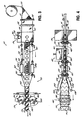
- FIG. 7 and 8 An additional feature of this invention is shown in Figs. 7 and 8 and is particularly adapted for use in constructing strings 12 of pocketed coil springs 14a having a barrel shaped configuration as shown in Fig. 7 .
- Barrel shaped springs 14a are well known in the industry and include a profile 108 in which the middle turns 110 of the spring 14a have a greater diameter than the top turn 112 and bottom turn 114 of the spring 14a.
- the top and bottom turns 112, 114 of the barrel shaped spring 14a may have a diameter of about 1.625 inches (4.1275cm) and the middle turn 110 have a diameter of about 2.5 inches (6.35cm).
- the transverse seam 80a adjacent to the spring 14a conforms to the profile 108 of the spring 1 4a as shown in Fig. 7 .
- the transverse seam 80a conforming to the profile 108 of the spring 14a encased in the pocket a tighter pocket is produced with less loose fabric 16 in the string 12 and a better overall product, especially with springs 14a having a non-linear profile.
- the transverse seam 80a adjacent thereto has a concave shape and because the transverse seam 80a is located between adjacent barrel shaped springs 14a the seam 80a may have a pair of outwardly facing concave shapes forming an X or similar configuration.
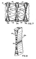
- a weld head 82a suitable for forming the transverse seam 80a is shown in Fig. 8 in which a number of studs 116 are arranged in the pattern shown so that adjacent studs 116 proximate the top and bottom of the weld head 82a are spaced farther apart than those in the middle to conform with the profiles 108 of the adjacent barrel shaped springs 14a.
- the transverse seam 80a of Fig. 7 is symmetric, other configurations are contemplated.
- this feature of the invention is useful not only for barrel shaped springs 14a to form a tighter, more conforming fabric pocket, but also for springs having a non-linear profile in general such as the barrel shaped springs and hour glass shaped springs in which the middle turns have a lesser diameter than the top and bottom turns.
Landscapes
- Engineering & Computer Science (AREA)
- Mechanical Engineering (AREA)
- Springs (AREA)
- Mattresses And Other Support Structures For Chairs And Beds (AREA)
- Wire Processing (AREA)
- Chain Conveyers (AREA)
- Organic Low-Molecular-Weight Compounds And Preparation Thereof (AREA)
- Casting Devices For Molds (AREA)
- Treatment Of Fiber Materials (AREA)
Claims (20)
- Verfahren zum Herstellen einer Folge von Spiralfedern in Taschen, umfassend das Zuführen eines Vorrats von Gewebe (16), Falten des Gewebes entlang einer longitudinalen Faltlinie in erste und zweite allgemein parallele Gewebelagen (24, 26), Einführen einer Reihe von axial komprimierten Federn (14, 14a) zwischen die erste und die zweite Lage (24, 26), Verbinden der ersten und der zweiten Lage miteinander durch Erzeugen einer Längsnaht (54) in der Nähe der freien Ränder (28) der ersten und der zweiten Lage (24, 26), Zulassen, dass die Federn (14, 14a) wenigstens teilweise axial in dem Gewebe in derselben Ausrichtung expandieren, in der sie zwischen die Lagen (24, 26) eingeführt wurden, so dass die Längsachse (60) jeder der Federn allgemein senkrecht zur Längsnaht (54) verläuft, und Erzeugen einer Quernaht (80, 80a) in dem Gewebe zwischen benachbarten Federn (14, 14a), um dadurch jede der Federn in einer Gewebetasche (86) einzuschließen, dadurch gekennzeichnet, dass zugelassen wird, dass die Federn (14, 14a) nach dem Verbinden der ersten und der zweiten Lage (24, 26) durch Erzeugen der Längsnaht (54) und vor dem Erzeugen der Quernähte (80, 80a), welche allgemein parallel zu den Längsachsen (60) der wenigstens teilweise expandierten Federn (14, 14a) erzeugt werden, wenigstens teilweise expandieren.
- Verfahren nach Anspruch 1, wobei die Ausrichtung der Längsachsen (60) der Federn (14, 14a) während des gesamten Prozesses allgemein unverändert bleibt.
- Verfahren nach einem der vorherigen Ansprüche, wobei die Expansion der Federn (14, 14a) durch ein Paar rotierender Elemente (72, 102) auf gegenüberliegenden Seiten der Federn in dem Gewebe gesteuert wird.
- Verfahren nach Anspruch 3, wobei die Rotationsachsen der rotierenden Elemente (72) allgemein parallel zu den Längsachsen (60) der Federn sind und jedes rotierende Element (72) eine Mehrzahl von bogenförmigen Aussparungen (76) umfasst, die in Kombination jede Feder teilweise umgeben.
- Verfahren nach Anspruch 3, wobei die Rotationsachsen der rotierenden Elemente allgemein senkrecht zu den Längsachsen (60) der Federn sind und jedes rotierende Element ein Band (102) umfasst, das über beabstandete Rollen (104, 106) passiert, wobei ein Trennabstand zwischen den Bändern (102) in einer Abwärtsrichtung zunimmt, um dadurch die Expansion der Federn (14, 14a) zwischen den Bändern zu steuern.
- Verfahren nach einem der vorherigen Ansprüche, ferner umfassend das Ziehen des Gewebes zwischen einem Paar rotierender Transportelemente (96), die auf gegenüberliegenden Seiten des Gewebes beabstandet sind und sich unterhalb von einer Position befinden, in der die Quernähte (80, 80a) gebildet sind, wobei die rotierenden Transportelemente (96) eine Mehrzahl von bogenförmigen Aussparungen (100) umfassen, die in Kombination jede Feder teilweise umgeben.
- Verfahren nach Anspruch 6, wobei der Schritt des Ziehens des Gewebes nach dem Erzeugen der Quernähte (80, 80a) durchgeführt wird.
- Verfahren nach einem der vorherigen Ansprüche, wobei das Einführen ferner das Einführen von komprimierten Federn (14a) umfasst, die ein allgemein nichtlinear gestaltetes Profil neben der Quernaht aufweisen, und das Bilden der Quernaht ferner das Bilden der Quernaht (80a) auf eine solche Weise umfasst, dass sie allgemein wenigstens einem Teil des Profils der benachbarten Federn (14a) entspricht.
- Verfahren nach Anspruch 8, wobei die eingeführten Federn (14a) fassförmig sind.
- Verfahren nach einem der Ansprüche 1 bis 7, wobei das Einführen ferner das Einführen von komprimierten fassförmigen Federn (14a) umfasst und das Erzeugen der Quernaht ferner das Erzeugen der Quernaht (80a) auf eine solche Weise umfasst, dass sie eine allgemein konkave Konfiguration neben den fassförmigen Federn (14a) hat.
- Verfahren nach einem der vorherigen Ansprüche, wobei das Gewebe ein thermoschweißbares Gewebe (16) ist und die Verbindungs- und Erzeugungsschritte durch Verschweißen des Gewebes miteinander durchgeführt werden.
- Verfahren nach einem der vorherigen Ansprüche, wobei die Längsnaht (54) allgemein auf der Seite der Federn (14, 14a) neben deren oberem und unterem Ende in der hergestellten Folge (12) von Spiralfedern in Taschen positioniert ist.
- System zum Bilden einer Folge (12) von Spiralfedern in Taschen, wobei jede der Federn (14, 14a) in einer aus Gewebe gebildeten Tasche (86) eingeschlossen ist, wobei das System Folgendes umfasst: eine Gewebezufuhrstation zum Bereitstellen einer ersten und einer zweiten allgemein parallelen Gewebelage (24, 26) als ein entlang einer longitudinalen Faltlinie gefaltetes Gewebe, eine Federeinführstation (34), in der axial komprimierte Federn (14, 14a) individuell zwischen die erste und die zweite Lage (24, 26) eingeführt werden, eine Längsnahterzeugungsstation (52), die sich der Federeinführstation (34) nachgeschaltet befindet, wobei die Längsnahterzeugungsstation (52) die erste und die zweite Lage (24, 26) des Gewebes miteinander durch Bilden einer Längsnaht (52) in der Nähe der freien Ränder (28) der ersten und der zweiten Lage verbindet, eine Federexpansionsstation (70), in der die Federn (14, 14a) wenigstens teilweise zwischen der ersten und der zweiten Lage (24, 26) in derselben Ausrichtung expandieren können, in der sie zwischen die Lagen (24, 26) eingeführt wurden, so dass die Längsachse (60) jeder Feder allgemein senkrecht zur Längsnaht (54) ist, eine Quernahterzeugungsstation (78) welche eine Quernaht (80, 80a) in dem Gewebe bildet, um jedes Paar benachbarter Federn (14, 14a) zu trennen und dadurch jede der Federn nach dem Einführen in einer Gewebetasche (86) einzuschließen, und eine Transportstation (62, 94), die das Gewebe (16) und die darin enthaltenen Federn (14, 14a) durch die jeweiligen Stationen bewegt, dadurch gekennzeichnet, dass sich die Federexpansionsstation der Längsnahterzeugungsstation nachgeschaltet befindet, und dadurch, dass die Quernahterzeugungsstation (78) die Quernähte (80, 80a) allgemein parallel zu den Längsachsen (60) der wenigstens teilweise expandierten Federn bildet, wobei sich die Quernahterzeugungsstation (78) der Federexpansionsstation (70) nachgeschaltet befindet.
- System nach Anspruch 13, wobei die Ausrichtung der Längsachsen (60) der Federn (14, 14a) von der Federeinführstation (34) durch die Herstellung der Folge (12) von Spiralfedern in Taschen allgemein unverändert bleibt.
- System nach einem der Ansprüche 13 oder 14, wobei die Transportstation (62, 94) ferner ein Paar von rotierenden Transportelementen (96) umfasst, die auf gegenüberliegenden Seiten des Gewebes beabstandet sind und sich unterhalb der Federexpansionsstation (70) befinden, wobei die rotierenden Transportelemente (96) eine Mehrzahl von bogenförmigen Aussparungen (100) umfassen, die in Kombination jede Feder (14, 14a) und das umgebende Gewebe teilweise umgeben, um dadurch das Gewebe und die darin enthaltenen Federn durch die jeweiligen Stationen zu ziehen.
- System nach einem der Ansprüche 13 bis 15, wobei die Federexpansionsstation (70) ferner ein Paar rotierender Elemente (72, 102) auf gegenüberliegenden Seiten der Federn (14, 14a) in dem Gewebe umfasst.
- System nach Anspruch 16, wobei die Rotationsachsen der rotierenden Elemente (72) allgemein parallel zu den Längsachsen (60) der Federn liegen und jedes rotierende Element (72) eine Mehrzahl von bogenförmigen Aussparungen (76) umfasst, die in Kombination jede Feder teilweise umgeben.
- System nach Anspruch 17, wobei die Rotationsachsen der rotierenden Elemente (102) allgemein senkrecht zu den Längsachsen (60) der Federn sind und jedes rotierende Element ein Band (102) umfasst, das über beabstandete rotational montierte Rollen (104, 106) passiert, wobei ein Trennabstand zwischen den Bändern (102) in einer Abwärtsrichtung zunimmt, um die Expansion der Federn zwischen den Bändern (102) dadurch zu steuern.
- System nach einem der Ansprüche 13 bis 18, wobei die Quernahterzeugungsstation (78) eine Quernaht (80a) bildet, die einem nichtlinearen Profil der benachbarten Feder (14a) entspricht.
- System nach einem der Ansprüche 13 bis 19, wobei die Längsnahterzeugungsstation (52) und die Quernahterzeugungsstation (78) jeweils einen Thermoschweißkopf und einen Amboss (56, 58, 82, 84) umfassen, die zum Bilden von Thermoschweißnähten in dem Gewebe zusammenwirken.
Priority Applications (1)
| Application Number | Priority Date | Filing Date | Title |
|---|---|---|---|
| DE60015318T DE60015318T3 (de) | 1999-04-16 | 2000-03-31 | Verfahren und system zum herstellen einer kette von taschenfedern |
Applications Claiming Priority (5)
| Application Number | Priority Date | Filing Date | Title |
|---|---|---|---|
| US29322199A | 1999-04-16 | 1999-04-16 | |
| US293221 | 1999-04-16 | ||
| US353483 | 1999-07-13 | ||
| US09/353,483 US6336305B1 (en) | 1999-04-16 | 1999-07-13 | System for forming strings of pocketed coil springs |
| PCT/IB2000/000396 WO2000063113A1 (en) | 1999-04-16 | 2000-03-31 | Method and system for forming strings of pocketed coil springs |
Publications (3)
| Publication Number | Publication Date |
|---|---|
| EP1171377A1 EP1171377A1 (de) | 2002-01-16 |
| EP1171377B1 EP1171377B1 (de) | 2004-10-27 |
| EP1171377B2 true EP1171377B2 (de) | 2012-06-13 |
Family
ID=23128205
Family Applications (1)
| Application Number | Title | Priority Date | Filing Date |
|---|---|---|---|
| EP00911198A Expired - Lifetime EP1171377B2 (de) | 1999-04-16 | 2000-03-31 | Verfahren und system zum herstellen einer kette von taschenfedern |
Country Status (14)
| Country | Link |
|---|---|
| EP (1) | EP1171377B2 (de) |
| JP (1) | JP4377074B2 (de) |
| CN (1) | CN1251959C (de) |
| AT (1) | ATE280735T1 (de) |
| AU (1) | AU3318900A (de) |
| BR (1) | BR0009482A (de) |
| CA (1) | CA2368852C (de) |
| DE (1) | DE60015318T3 (de) |
| ES (1) | ES2232431T5 (de) |
| GB (1) | GB2358796B (de) |
| MX (1) | MXPA01010382A (de) |
| PT (1) | PT1171377E (de) |
| TR (1) | TR200102879T2 (de) |
| WO (1) | WO2000063113A1 (de) |
Families Citing this family (13)
| Publication number | Priority date | Publication date | Assignee | Title |
|---|---|---|---|---|
| US6591436B2 (en) * | 1999-04-16 | 2003-07-15 | Spuhl Ag St. Gallen | Side seam pocketed coil springs |
| US6260331B1 (en) * | 1999-06-17 | 2001-07-17 | Sidhil Technology, Llc | Method and apparatus for the manufacture of pocketed springs |
| GB2358349B (en) * | 2000-10-12 | 2001-12-12 | Spuhl Ag St Gallen | Method and system for forming strings of pocketed coil springs |
| RU2302992C2 (ru) * | 2004-05-26 | 2007-07-20 | Ирина Дмитриевна Егорова | Устройство для изготовления трубчатой оболочки с цепочкой независимо деформирующихся цилиндрических пружин |
| SE530089C2 (sv) * | 2004-10-18 | 2008-02-26 | Stjernfjaedrar Ab | Resårmadrass, såsom pocketmadrass, metod för tillverkning av sådan resårmadrass samt anordning för tillverkning av sådan resårmadrass |
| CN101955150B (zh) * | 2010-07-30 | 2012-11-14 | 严卓晟 | 连续滚动袋装弹簧机 |
| PL2565152T3 (pl) * | 2011-08-30 | 2014-11-28 | Spuehl Ag | Urządzenie do tworzenia rękawa z materiału kieszeni i sposób wytwarzania rzędu sprężyn kieszeniowych |
| US9427090B2 (en) * | 2013-06-19 | 2016-08-30 | L&P Property Management Company | Pocketed spring assembly comprising strings of springs having Y-shaped seams |
| CN106185780A (zh) * | 2016-06-28 | 2016-12-07 | 广州市联柔机械设备有限公司 | 双层布袋弹簧制作装置及方法 |
| ES2978585T3 (es) * | 2019-05-14 | 2024-09-16 | Bekaert Sa Nv | Bobina de resortes ensacados |
| KR102134553B1 (ko) * | 2020-02-13 | 2020-07-16 | 김선용 | 포켓 스프링 자동 정렬 인입장치 |
| CN112596161B (zh) * | 2020-12-21 | 2023-03-24 | 成都市加朗星科技有限公司 | 一种多层结构的模斑转换器及其实现方法 |
| CN113638136B (zh) * | 2021-08-12 | 2025-08-05 | 广州市联柔机械设备有限公司 | 缝线袋装弹簧的制造设备及制造方法 |
Citations (2)
| Publication number | Priority date | Publication date | Assignee | Title |
|---|---|---|---|---|
| US4439977A (en) † | 1977-05-05 | 1984-04-03 | Simmons U.S.A. Corporation | Method and apparatus for making a series of pocketed coil springs |
| US4584023A (en) † | 1984-10-31 | 1986-04-22 | Chevron Research Company | Method for producing industrial asphalts without air-blowing using phytic acid |
Family Cites Families (4)
| Publication number | Priority date | Publication date | Assignee | Title |
|---|---|---|---|---|
| US4234983A (en) | 1978-10-02 | 1980-11-25 | Simmons Company | Thermally welded spring pockets |
| US5613287A (en) | 1995-06-07 | 1997-03-25 | Simmons Company | Method for forming strings of pocketed springs |
| US5749133A (en) * | 1996-09-10 | 1998-05-12 | Simmons Company | Method and apparatus for forming strings of pocketed springs |
| SE9704746L (sv) * | 1997-12-19 | 1998-11-09 | Stjernfjaedrar Ab | Dubbelfjädermadrass samt tillverkningsmetod för en sådan madrass |
-
2000
- 2000-03-31 JP JP2000612214A patent/JP4377074B2/ja not_active Expired - Fee Related
- 2000-03-31 MX MXPA01010382A patent/MXPA01010382A/es active IP Right Grant
- 2000-03-31 GB GB0108713A patent/GB2358796B/en not_active Expired - Fee Related
- 2000-03-31 EP EP00911198A patent/EP1171377B2/de not_active Expired - Lifetime
- 2000-03-31 AT AT00911198T patent/ATE280735T1/de active
- 2000-03-31 DE DE60015318T patent/DE60015318T3/de not_active Expired - Lifetime
- 2000-03-31 ES ES00911198T patent/ES2232431T5/es not_active Expired - Lifetime
- 2000-03-31 PT PT00911198T patent/PT1171377E/pt unknown
- 2000-03-31 BR BR0009482-0A patent/BR0009482A/pt not_active Application Discontinuation
- 2000-03-31 CN CNB008062250A patent/CN1251959C/zh not_active Expired - Fee Related
- 2000-03-31 TR TR2001/02879T patent/TR200102879T2/xx unknown
- 2000-03-31 CA CA002368852A patent/CA2368852C/en not_active Expired - Fee Related
- 2000-03-31 WO PCT/IB2000/000396 patent/WO2000063113A1/en not_active Ceased
- 2000-03-31 AU AU33189/00A patent/AU3318900A/en not_active Abandoned
Patent Citations (2)
| Publication number | Priority date | Publication date | Assignee | Title |
|---|---|---|---|---|
| US4439977A (en) † | 1977-05-05 | 1984-04-03 | Simmons U.S.A. Corporation | Method and apparatus for making a series of pocketed coil springs |
| US4584023A (en) † | 1984-10-31 | 1986-04-22 | Chevron Research Company | Method for producing industrial asphalts without air-blowing using phytic acid |
Also Published As
| Publication number | Publication date |
|---|---|
| DE60015318T2 (de) | 2005-11-24 |
| ATE280735T1 (de) | 2004-11-15 |
| JP4377074B2 (ja) | 2009-12-02 |
| EP1171377A1 (de) | 2002-01-16 |
| CN1251959C (zh) | 2006-04-19 |
| GB2358796B (en) | 2001-12-12 |
| CA2368852C (en) | 2008-12-16 |
| BR0009482A (pt) | 2002-03-26 |
| GB0108713D0 (en) | 2001-05-30 |
| WO2000063113A1 (en) | 2000-10-26 |
| TR200102879T2 (tr) | 2002-04-22 |
| DE60015318D1 (de) | 2004-12-02 |
| GB2358796A (en) | 2001-08-08 |
| PT1171377E (pt) | 2005-04-29 |
| CN1355766A (zh) | 2002-06-26 |
| AU3318900A (en) | 2000-11-02 |
| EP1171377B1 (de) | 2004-10-27 |
| ES2232431T3 (es) | 2005-06-01 |
| ES2232431T5 (es) | 2012-10-22 |
| MXPA01010382A (es) | 2002-03-27 |
| DE60015318T3 (de) | 2012-11-08 |
| CA2368852A1 (en) | 2000-10-26 |
| JP2002541943A (ja) | 2002-12-10 |
Similar Documents
| Publication | Publication Date | Title |
|---|---|---|
| US6591436B2 (en) | Side seam pocketed coil springs | |
| US6834477B2 (en) | Method and system for forming strings of pocketed coil springs with traction mechanism | |
| US6336305B1 (en) | System for forming strings of pocketed coil springs | |
| CA2223799C (en) | Method and apparatus for forming strings of pocketed springs | |
| EP1171377B2 (de) | Verfahren und system zum herstellen einer kette von taschenfedern | |
| EP0928283B1 (de) | Verfahren und vorrichtung zum herstellen von taschenfedern | |
| US6499275B1 (en) | Method and system for forming strings of pocketed coil springs | |
| GB2581582A (en) | Pocketed spring unit and method of manufacture | |
| GB2362096A (en) | Strings of pocketed coil springs | |
| GB2358349A (en) | Method and system for forming strings of pocketed coil springs | |
| HK1019871B (en) | Method and apparatus for forming pocketed springs | |
| HK1010180B (en) | Method for forming strings of pocketed springs | |
| MXPA97009661A (en) | Method and apparatus for forming resort chains embolsa | |
| MXPA99002327A (en) | Method and apparatus for forming pocketed springs |
Legal Events
| Date | Code | Title | Description |
|---|---|---|---|
| PUAI | Public reference made under article 153(3) epc to a published international application that has entered the european phase |
Free format text: ORIGINAL CODE: 0009012 |
|
| 17P | Request for examination filed |
Effective date: 20011002 |
|
| AK | Designated contracting states |
Kind code of ref document: A1 Designated state(s): AT BE CH CY DE DK ES FI FR GB GR IE IT LI LU MC NL PT SE |
|
| 17Q | First examination report despatched |
Effective date: 20030723 |
|
| GRAP | Despatch of communication of intention to grant a patent |
Free format text: ORIGINAL CODE: EPIDOSNIGR1 |
|
| GRAS | Grant fee paid |
Free format text: ORIGINAL CODE: EPIDOSNIGR3 |
|
| GRAA | (expected) grant |
Free format text: ORIGINAL CODE: 0009210 |
|
| AK | Designated contracting states |
Kind code of ref document: B1 Designated state(s): AT BE CH CY DE DK ES FI FR GB GR IE IT LI LU MC NL PT SE |
|
| PG25 | Lapsed in a contracting state [announced via postgrant information from national office to epo] |
Ref country code: BE Free format text: LAPSE BECAUSE OF FAILURE TO SUBMIT A TRANSLATION OF THE DESCRIPTION OR TO PAY THE FEE WITHIN THE PRESCRIBED TIME-LIMIT Effective date: 20041027 Ref country code: FI Free format text: LAPSE BECAUSE OF FAILURE TO SUBMIT A TRANSLATION OF THE DESCRIPTION OR TO PAY THE FEE WITHIN THE PRESCRIBED TIME-LIMIT Effective date: 20041027 Ref country code: NL Free format text: LAPSE BECAUSE OF FAILURE TO SUBMIT A TRANSLATION OF THE DESCRIPTION OR TO PAY THE FEE WITHIN THE PRESCRIBED TIME-LIMIT Effective date: 20041027 |
|
| REG | Reference to a national code |
Ref country code: GB Ref legal event code: FG4D |
|
| REG | Reference to a national code |
Ref country code: CH Ref legal event code: EP |
|
| RBV | Designated contracting states (corrected) |
Designated state(s): AT BE CH CY DE DK ES FI FR GR IE IT LI LU MC NL PT SE |
|
| REG | Reference to a national code |
Ref country code: IE Ref legal event code: FG4D |
|
| REF | Corresponds to: |
Ref document number: 60015318 Country of ref document: DE Date of ref document: 20041202 Kind code of ref document: P |
|
| REG | Reference to a national code |
Ref country code: GB Ref legal event code: ERR Free format text: NOTIFICATION HAS BEEN RECEIVED FROM THE EUROPEAN PATENT OFFICE THAT THIS DESIGNATION HAS BEEN WITHDRAWN. THIS CORRECTION WILL BE PUBLISHED IN EUROPEAN PATENT BULLETIN NO. 04/46 OF 20041110. |
|
| PG25 | Lapsed in a contracting state [announced via postgrant information from national office to epo] |
Ref country code: DK Free format text: LAPSE BECAUSE OF FAILURE TO SUBMIT A TRANSLATION OF THE DESCRIPTION OR TO PAY THE FEE WITHIN THE PRESCRIBED TIME-LIMIT Effective date: 20050127 |
|
| REG | Reference to a national code |
Ref country code: CH Ref legal event code: NV Representative=s name: BRAUNPAT BRAUN EDER AG |
|
| REG | Reference to a national code |
Ref country code: GR Ref legal event code: EP Ref document number: 20050400346 Country of ref document: GR |
|
| PG25 | Lapsed in a contracting state [announced via postgrant information from national office to epo] |
Ref country code: CY Free format text: LAPSE BECAUSE OF FAILURE TO SUBMIT A TRANSLATION OF THE DESCRIPTION OR TO PAY THE FEE WITHIN THE PRESCRIBED TIME-LIMIT Effective date: 20050331 Ref country code: MC Free format text: LAPSE BECAUSE OF NON-PAYMENT OF DUE FEES Effective date: 20050331 Ref country code: LU Free format text: LAPSE BECAUSE OF NON-PAYMENT OF DUE FEES Effective date: 20050331 Ref country code: IE Free format text: LAPSE BECAUSE OF NON-PAYMENT OF DUE FEES Effective date: 20050331 |
|
| REG | Reference to a national code |
Ref country code: PT Ref legal event code: SC4A Free format text: AVAILABILITY OF NATIONAL TRANSLATION Effective date: 20050216 |
|
| NLV1 | Nl: lapsed or annulled due to failure to fulfill the requirements of art. 29p and 29m of the patents act | ||
| REG | Reference to a national code |
Ref country code: ES Ref legal event code: FG2A Ref document number: 2232431 Country of ref document: ES Kind code of ref document: T3 |
|
| PLBI | Opposition filed |
Free format text: ORIGINAL CODE: 0009260 |
|
| PLAX | Notice of opposition and request to file observation + time limit sent |
Free format text: ORIGINAL CODE: EPIDOSNOBS2 |
|
| 26 | Opposition filed |
Opponent name: ET EUROTECH (CYPRUS) LTD. Effective date: 20050707 |
|
| ET | Fr: translation filed | ||
| PLAF | Information modified related to communication of a notice of opposition and request to file observations + time limit |
Free format text: ORIGINAL CODE: EPIDOSCOBS2 |
|
| REG | Reference to a national code |
Ref country code: IE Ref legal event code: MM4A |
|
| PLBB | Reply of patent proprietor to notice(s) of opposition received |
Free format text: ORIGINAL CODE: EPIDOSNOBS3 |
|
| APAH | Appeal reference modified |
Free format text: ORIGINAL CODE: EPIDOSCREFNO |
|
| APBP | Date of receipt of notice of appeal recorded |
Free format text: ORIGINAL CODE: EPIDOSNNOA2O |
|
| APBQ | Date of receipt of statement of grounds of appeal recorded |
Free format text: ORIGINAL CODE: EPIDOSNNOA3O |
|
| APBP | Date of receipt of notice of appeal recorded |
Free format text: ORIGINAL CODE: EPIDOSNNOA2O |
|
| APBQ | Date of receipt of statement of grounds of appeal recorded |
Free format text: ORIGINAL CODE: EPIDOSNNOA3O |
|
| APAH | Appeal reference modified |
Free format text: ORIGINAL CODE: EPIDOSCREFNO |
|
| APBU | Appeal procedure closed |
Free format text: ORIGINAL CODE: EPIDOSNNOA9O |
|
| PUAH | Patent maintained in amended form |
Free format text: ORIGINAL CODE: 0009272 |
|
| STAA | Information on the status of an ep patent application or granted ep patent |
Free format text: STATUS: PATENT MAINTAINED AS AMENDED |
|
| 27A | Patent maintained in amended form |
Effective date: 20120613 |
|
| AK | Designated contracting states |
Kind code of ref document: B2 Designated state(s): AT BE CH CY DE DK ES FI FR GR IE IT LI LU MC NL PT SE |
|
| REG | Reference to a national code |
Ref country code: CH Ref legal event code: AEN Free format text: BREVET MAINTENU DANS UNE FORME MODIFIEE |
|
| REG | Reference to a national code |
Ref country code: DE Ref legal event code: R102 Ref document number: 60015318 Country of ref document: DE Effective date: 20120613 |
|
| REG | Reference to a national code |
Ref country code: SE Ref legal event code: RPEO |
|
| REG | Reference to a national code |
Ref country code: ES Ref legal event code: DC2A Ref document number: 2232431 Country of ref document: ES Kind code of ref document: T5 Effective date: 20121022 |
|
| REG | Reference to a national code |
Ref country code: GR Ref legal event code: EP Ref document number: 20120401833 Country of ref document: GR Effective date: 20120920 |
|
| REG | Reference to a national code |
Ref country code: FR Ref legal event code: PLFP Year of fee payment: 16 |
|
| PGFP | Annual fee paid to national office [announced via postgrant information from national office to epo] |
Ref country code: IT Payment date: 20150225 Year of fee payment: 16 Ref country code: PT Payment date: 20150330 Year of fee payment: 16 Ref country code: ES Payment date: 20150212 Year of fee payment: 16 Ref country code: CH Payment date: 20150313 Year of fee payment: 16 |
|
| PGFP | Annual fee paid to national office [announced via postgrant information from national office to epo] |
Ref country code: FR Payment date: 20150309 Year of fee payment: 16 Ref country code: AT Payment date: 20150225 Year of fee payment: 16 Ref country code: GR Payment date: 20150211 Year of fee payment: 16 |
|
| PGFP | Annual fee paid to national office [announced via postgrant information from national office to epo] |
Ref country code: DE Payment date: 20160322 Year of fee payment: 17 |
|
| PGFP | Annual fee paid to national office [announced via postgrant information from national office to epo] |
Ref country code: SE Payment date: 20160329 Year of fee payment: 17 |
|
| REG | Reference to a national code |
Ref country code: CH Ref legal event code: PL |
|
| REG | Reference to a national code |
Ref country code: AT Ref legal event code: MM01 Ref document number: 280735 Country of ref document: AT Kind code of ref document: T Effective date: 20160331 |
|
| PG25 | Lapsed in a contracting state [announced via postgrant information from national office to epo] |
Ref country code: PT Free format text: LAPSE BECAUSE OF NON-PAYMENT OF DUE FEES Effective date: 20160930 |
|
| REG | Reference to a national code |
Ref country code: FR Ref legal event code: ST Effective date: 20161130 |
|
| PG25 | Lapsed in a contracting state [announced via postgrant information from national office to epo] |
Ref country code: CH Free format text: LAPSE BECAUSE OF NON-PAYMENT OF DUE FEES Effective date: 20160331 Ref country code: LI Free format text: LAPSE BECAUSE OF NON-PAYMENT OF DUE FEES Effective date: 20160331 Ref country code: FR Free format text: LAPSE BECAUSE OF NON-PAYMENT OF DUE FEES Effective date: 20160331 |
|
| REG | Reference to a national code |
Ref country code: GR Ref legal event code: ML Ref document number: 20120401833 Country of ref document: GR Effective date: 20161006 |
|
| PG25 | Lapsed in a contracting state [announced via postgrant information from national office to epo] |
Ref country code: GR Free format text: LAPSE BECAUSE OF NON-PAYMENT OF DUE FEES Effective date: 20161006 Ref country code: IT Free format text: LAPSE BECAUSE OF NON-PAYMENT OF DUE FEES Effective date: 20160331 Ref country code: AT Free format text: LAPSE BECAUSE OF NON-PAYMENT OF DUE FEES Effective date: 20160331 |
|
| REG | Reference to a national code |
Ref country code: ES Ref legal event code: FD2A Effective date: 20170427 |
|
| PG25 | Lapsed in a contracting state [announced via postgrant information from national office to epo] |
Ref country code: ES Free format text: LAPSE BECAUSE OF NON-PAYMENT OF DUE FEES Effective date: 20160401 |
|
| REG | Reference to a national code |
Ref country code: DE Ref legal event code: R119 Ref document number: 60015318 Country of ref document: DE |
|
| PG25 | Lapsed in a contracting state [announced via postgrant information from national office to epo] |
Ref country code: DE Free format text: LAPSE BECAUSE OF NON-PAYMENT OF DUE FEES Effective date: 20171003 |
|
| PG25 | Lapsed in a contracting state [announced via postgrant information from national office to epo] |
Ref country code: SE Free format text: LAPSE BECAUSE OF NON-PAYMENT OF DUE FEES Effective date: 20170401 |