EP1172184A1 - Dispositif de contrôle de la position d'un flasque de robot dans son environnement - Google Patents
Dispositif de contrôle de la position d'un flasque de robot dans son environnement Download PDFInfo
- Publication number
- EP1172184A1 EP1172184A1 EP01401681A EP01401681A EP1172184A1 EP 1172184 A1 EP1172184 A1 EP 1172184A1 EP 01401681 A EP01401681 A EP 01401681A EP 01401681 A EP01401681 A EP 01401681A EP 1172184 A1 EP1172184 A1 EP 1172184A1
- Authority
- EP
- European Patent Office
- Prior art keywords
- sensor
- axis
- cylindrical surface
- probe
- central axis
- Prior art date
- Legal status (The legal status is an assumption and is not a legal conclusion. Google has not performed a legal analysis and makes no representation as to the accuracy of the status listed.)
- Withdrawn
Links
- 239000000523 sample Substances 0.000 claims description 27
- 238000006073 displacement reaction Methods 0.000 claims description 16
- 238000005259 measurement Methods 0.000 claims description 15
- 230000000694 effects Effects 0.000 claims description 3
- 238000001514 detection method Methods 0.000 abstract 1
- 238000000034 method Methods 0.000 description 4
- 230000000295 complement effect Effects 0.000 description 2
- 238000004804 winding Methods 0.000 description 2
- 238000013459 approach Methods 0.000 description 1
- 239000000470 constituent Substances 0.000 description 1
- 230000001939 inductive effect Effects 0.000 description 1
- 238000004519 manufacturing process Methods 0.000 description 1
- 238000012544 monitoring process Methods 0.000 description 1
- 238000013519 translation Methods 0.000 description 1
- 230000000007 visual effect Effects 0.000 description 1
Images


Classifications
-
- B—PERFORMING OPERATIONS; TRANSPORTING
- B25—HAND TOOLS; PORTABLE POWER-DRIVEN TOOLS; MANIPULATORS
- B25J—MANIPULATORS; CHAMBERS PROVIDED WITH MANIPULATION DEVICES
- B25J13/00—Controls for manipulators
- B25J13/08—Controls for manipulators by means of sensing devices, e.g. viewing or touching devices
- B25J13/088—Controls for manipulators by means of sensing devices, e.g. viewing or touching devices with position, velocity or acceleration sensors
- B25J13/089—Determining the position of the robot with reference to its environment
Definitions
- the invention relates to a device for monitoring the flange position tool holder of a robot in its environment.
- this location is done in two stages.
- the first is to position the part on a tool which we know precisely the position relative to a reference frame, which allows to deduce the position and the orientation of the part with respect to this mark of reference.
- the second is to locate the position and the orientation of the robot flange with respect to this reference mark reference, to deduce the position and orientation of the workpiece and the tool mounted on the flange.
- a known method consists in characterize a preferential axis in a reference linked to the flange, and bring this axis into coincidence with an axis of known position and orientation reference relative at the reference mark.
- a device for controlling the position of a robot flange in its environment comprising of a share a socket linked to one of the two elements of the flange or the environment, of known position relative to this element, and on the other hand a sensor linked to the other element and known position relative to this element, arranged to locate the axis of the socket.
- the robot is maneuvered and brought into such a position the sensor identifies the axis of the socket.
- a preferential axis linked to the element which carries the sensor is in coincidence with the axis of the socket carried by the other element. This maneuver can be automated, which makes it fast and repeatable.
- the position of the robot flange is indifferent by rotation around the axis linked to the environment and by displacement along this axis.
- Such a sensor comprising a body with central axis carrying at least four feelers arranged to cooperate with the cylindrical surface inside of the socket, and movable mounted on the body in radial directions contained in two planes of separate measure.
- the four probes are used to obtain information significant from the distance from the inner surface of the socket to the central axis of the body in one direction radial to this central axis. We compare this information to four instructions, and we decide that the sensor is good positioned on the axis of the socket when the four information is equal to the instructions. We show that four such pieces of information are sufficient to determine the inner surface of the socket, so its axis. This procedure is based only on information obtained by contact, which removes any character from subjectivity to the operation.
- the directions mobility probes are contained in pairs in each of the measurement planes.
- these directions are orthogonal to each other in at least one measurement plan.
- the radial directions of mobility of the probes of a measurement plane are opposed to those contained in the other measurement plan.
- At least one probe is subjected to the effect of an elastic return means towards a limit stop for its radial extension.
- This extension is fixed slightly higher than the diameter of the inner cylindrical surface of the socket, to guarantee contact of the probe with the area.
- At least one probe consists of a contact pad with the cylindrical surface projecting from the end of a lever articulated on the body.
- the lever is articulated along an axis substantially perpendicular to the central axis and in the radial direction
- This arrangement makes it possible to simply obtain the radial displacement of the stud under the effect of its contact with the cylindrical surface.
- the probe cooperates with the movable end of a displacement sensor linked to the body delivering electrical information significant of the distance along the radial direction of the cylindrical surface to the central axis.
- This information is compared to guidelines for indicate whether the sensor has recognized the axis of the socket or no.
- the senor is provided with a means for locating an angular position around axis.
- This means makes it possible to determine the direction of two normal axes to that previously identified, to define the orientation of a reference mark.
- the position of the sensor is determined along the axis of the socket.
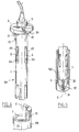
- a sensor 101 comprises a substantially cylindrical body 1 circular with central axis X, comprising at one of its ends a flange 2 and a portion of cylinder 3 for positioning on the flange of a robot whose wants to align the materialized direction defined by the axis central X on a known direction of the environment of the robot.
- This body 1 carries four feelers A, B, C, D.
- the constituent elements of each probe very similar, if not identical, receive index of their reference the lower case letter corresponding to the capital letter referencing the probe.
- These probes A, B, C, D are composed of a lever 4a, 4b, 4c, 4d rotatably mounted on the body along an axis articulation 5a, 5b, 5c, 5d contained in a plane normal to the X axis and perpendicular to it.
- the levers 4a, 4b, 4c, 4d extend from their axes of articulation 5a, 5b, 5c, 5d in a direction substantially parallel to the X axis, all in the same direction.
- the articulation axes 5a, 5b are perpendicular between them, and concurrent.
- the axes of articulation 5c, 5d are perpendicular to each other and concurrent.
- the two planes defined by these two pairs of axes are parallel, and axially offset along the central axis X.
- Axis 5a is parallel to axis 5c, while axis 5b is parallel to axis 5d.
- the four axes 5a, 5b, 5c, 5d are at the same distance from central axis X.
- the levers 4a, 4b, 4c, 4d project externally at their end respectively a contact pad 6a, 6b, 6c, 6d (the plot 6d is not visible), intended for cooperate with a circular cylindrical surface 7 inside of a socket 100, according to a contact zone noticeably punctual.
- these pads 6a, 6b, 6c, 6d affect the shape of a portion of a sphere whose apex comes into contact with the cylindrical surface 7.
- the apexes pads 6a, 6b, 6c, 6d are each located in a plane containing the central axis X.
- the apices of the pads 6a and 6b are located in a measurement plane P1 normal to the central axis X.
- the apices of the pads 6c, 6d are located in a plane P2 normal to the central axis X, and axially offset of the measurement plane P1.
- the diameter of the body 1 will be chosen smaller than that of the cylindrical surface 7, with a margin sufficient compatible with visual introduction by the operator of the sensor 101 in the socket 100 materializing the cylindrical surface 7. For example for a socket 100 30 mm in diameter, we will choose a body 28 mm in diameter.
- levers each carry a return lever square, respectively 8a, 8b, 8c, 8d, (the reference 8b and 8d are not shown), extending towards inside the body 1 and each cooperating with one of the stops 9a, 9b, 9c, 9d (stop 9b is not shown) integral with the body 1, arranged to limit rotation levers 4a, 4b, 4c, 4d, in order to delimit the extension radial of the studs 6a, 6b, 6c, 6d.
- This radial extension will advantageously be chosen slightly larger than the radius of the surface cylindrical 7, to ensure that the contact of the pad 6a, 6b, 6c, 6d with this surface 7 forces the return lever to leave the abutment 9a, 9b, 9c, 9d.
- This body also supports four sensors displacement 10a, 10b, 10c, 10d of slender shape comprising a fixed part 11a, 11b, 11c, 11d secured to the body 1 in which is slidably mounted a completed movable part by a head 12a, 12b, 12c, 12d.
- sensors 10a, 10b, 10c, 10d are arranged substantially along the X axis, so that their heads 12a, 12b, 12c, 12d each cooperate with the return lever 8a, 8b, 8c, 8d, so that the heads 12a, 12b, 12c, 12d approach their fixed parts respective 11a, 11b, 11c, 11d when the corresponding lever 4a, 4b, 4c, 4d moves in the direction of rotation which is not prohibited by stops 9a, 9b, 9c, 9d.
- the contact of the pad 6a, 6b, 6c, 6d on the surface cylindrical 7 induces a rotation of the lever 4a, 4b, 4c, 4d, and so the return lever 8a, 8b, 8c, 8d, which moves the displacement sensor head 12a, 12b, 12c, 12d 10a, 10b, 10c, 10d, which delivers information in response significant of the displacement of the stud.
- This information is compared to values of instructions which indicate whether the distance from the surface cylindrical 7 to the central axis X in the radial direction is less, equal or greater than a distance determined by the set value.
- the displacement sensors 10a, 10b, 10c, 10d are of preference of type LVDT (in English: Linear Variable Differential Transformer), implementing a winding primary carried by the fixed part 11a, 11b, 11c, 11d inducing in two secondary windings of voltages U1 and U2 of which the variation is substantially proportional to the axial displacement of a core linked to the head 12a, 12b, 12c, 12d.
- type LVDT in English: Linear Variable Differential Transformer
- Figure 2 is an enlarged perspective view of a pair of feelers in the relative arrangement they occupy in body 1. We are more particularly interested in probes A and B, but the description would be very similar for probes C and D.
- the measurement planes P1 and P2 are offset axially a sufficient distance to accommodate in the length of the body 1 the levers 4a and 4b, as well as the displacement sensors 10c and 10d.
- reference levers 8a, 8b have been designed to keep the sensor as far away from displacement 10a, 10b of the hinge pin 5a, 5b, this in order to obtain a better resolution of the sensor.
- cross arrangement of said reference levers 8a, 8b are provided with notches parallelepipedic 13a and 13b complementary (similar carpenters' half-cuts) to prevent them from interfere with each other during their angular deflections around their axes of articulation 5a, 5b.
- the sensors 10c and 10d being exactly to the right of the reference levers 8a and 8b, of the passages 14a and 14b are provided in said levers of return to let the electric wires 15c and 15d supplying the displacement sensors 10c and 10d up to the extremity of the body 1.
- These passages have no counterpart on the reference levers 8c and 8d, since no wire should pass through them.
- lever 4b provided with its return lever 8b, the notch 13b complementary to the notch 13a carried by the lever reference 8a, and passage 15b.
- This lever is articulated by axis 5b, and carries a pad 6b.
- the Yb axis of the sensor 10b substantially at the central axis X, as well as the contact zone 16b of the head 12b of the sensor 10b on the return lever 8b.
- This zone 16b is at the end of the return lever 8b opposite to that carrying the axis 5b.
- Figure 4 a sensor 101 putting in works the device described above, additionally comprising a angular sensor 20 and an axial sensor 21. We go below explain how such a sensor can spot the position and orientation of a reference mark in space.
- the angular sensor 20 is an electrical sensor likely to come into contact with a point 24 with the stop 22, along a surface contained in a plane passing through the axis of the cylindrical surface 7.
- the sensor axial 21 is an electrical sensor capable of to come into contact by means of a point 25 with the stop 23, here carried by the end face of the sleeve 100 bearing the cylindrical surface 7.
- FIG. 5 a variant of the sensor 101 is presented.
- the axial sensor 30 is a sensor LVDT type mounted substantially along the central axis X, of which the movable part ends with a head 31 intended for cooperate with the bottom 32 of the socket 100.
- This sensor axial 30 can be mounted in sensor 101 through deflection levers 8c and 8d, by means of openings not represented here practiced in each return lever 8c and 8d at their notches 13c and 13d (not shown, but similar to notches 13a and 13b).
- probes A, B, C, D mounted rotating along a vertical axis, and making them cooperate with displacement sensors mounted axially by means of of an oblique surface integral with the probe.
- the sensor angular 20 and the axial sensor 21 can be placed in an arbitrary position with respect to the sensors A, B, C, D.
- the angular sensor 21 could be a sensor optics capable of identifying a mark made on the face end of the sleeve 100 carrying the surface cylindrical 7.
Landscapes
- Engineering & Computer Science (AREA)
- Human Computer Interaction (AREA)
- Robotics (AREA)
- Mechanical Engineering (AREA)
- Length Measuring Devices With Unspecified Measuring Means (AREA)
Abstract
Description
- la figure 1 est une vue de l'agencement général d'un senseur selon l'invention ;
- la figure 2 est une vue en perspective de l'agencement d'une paire de palpeurs d'un plan de mesure du même senseur ;
- la figure 3 est une vue en perspective d'un levier constitutif d'un des palpeurs équipant le même senseur ;
- la figure 4 est une vue en perspective d'un senseur selon l'invention muni d'un capteur axial et d'un capteur angulaire ;
- la figure 5 est une vue en perspective d'un autre senseur selon l'invention muni d'un capteur axial.
Claims (9)
- Dispositif de contrôle de la position d'un flasque de robot dans son environnement, comprenant d'une part une douille (100) liée à l'un des deux éléments du flasque et de l'environnement et de position connue relativement à cet élément, et d'autre part un senseur (101) lié à l'autre élément et de position connue relativement à cet élément, le senseur (101) comportant un corps (1) à axe central (X) portant au moins quatre palpeurs (A,B,C,D) agencés pour coopérer avec la surface cylindrique (7) intérieure de la douille (100), et montés mobiles sur le corps (1) selon des directions radiales contenues dans deux plans de mesure (P1,P2) distincts, les directions de mobilité des palpeurs (A,B,C,D) étant contenues par paires dans chaque plan de mesure (P1,P2), caractérisé en ce que les directions de mobilité des palpeurs (A,B,C,D) sont orthogonales entre elles dans au moins un plan de mesure (P1,P2).
- Dispositif selon la revendication 1, caractérisé en ce que les directions radiales de mobilité des palpeurs (A,B,C,D) d'un plan de mesure (P1) sont opposées à celles contenues dans l'autre plan de mesure (P2).
- Dispositif selon l'une des revendications précédentes, caractérisé en ce qu'au moins un palpeur (A,B,C,D) est soumis à l'effet d'un moyen élastique de rappel en direction d'une butée (9a,9b,9c,9d) de limitation de son extension radiale.
- Dispositif selon l'une des revendications précédentes, caractérisé en ce qu'au moins un palpeur (A,B,C,D) est constitué d'un plot de contact (6a,6b,6c,6d) avec la surface cylindrique 7 en saillie de l'extrémité d'un levier (4a,4b,4c,4d) articulé sur le corps (1).
- Dispositif selon la revendication 4, caractérisé en ce que le levier (4a,4b,4c,4d) est articulé selon un axe (5a,5b,5c,5d) sensiblement perpendiculaire à l'axe central (X) .
- Dispositif selon l'une des revendications précédentes, caractérisé en ce que le palpeur (A,B,C,D) coopère avec un capteur de déplacement (10a,10b,10c,10d) par une tête (12a,12b,12c,12d) à l'extrémité de sa partie mobile, délivrant une information significative de la distance de la surface cylindrique (7) à l'axe central (X) selon la direction radiale de mobilité du palpeur (A,B,C,D).
- Dispositif selon la revendication 6, caractérisé en ce que le capteur de déplacement (10a,10b,10c,10d) est agencé parallèlement à l'axe central (X), et coopère avec le palpeur (A,B,C,D) au moyen d'un levier de renvoi (8a,8b,8c,8d) solidaire du palpeur (A,B,C,D).
- Dispositif selon l'une des revendications précédentes, caractérisé en ce qu'il est pourvu d'au moins un capteur (20) pour coopérer avec un obstacle angulaire (21) lié à la surface cylindrique (7).
- Dispositif selon l'une des revendications précédentes, caractérisé en ce qu'il est pourvu d'au moins un capteur (22;30) pour coopérer avec un obstacle axial (23;32) lié à la surface cylindrique (7).
Applications Claiming Priority (2)
| Application Number | Priority Date | Filing Date | Title |
|---|---|---|---|
| FR0008721A FR2811253B1 (fr) | 2000-07-05 | 2000-07-05 | Dispositif de controle de la position d'un flasque de robot dans son environnement |
| FR0008721 | 2000-07-05 |
Publications (1)
| Publication Number | Publication Date |
|---|---|
| EP1172184A1 true EP1172184A1 (fr) | 2002-01-16 |
Family
ID=8852116
Family Applications (1)
| Application Number | Title | Priority Date | Filing Date |
|---|---|---|---|
| EP01401681A Withdrawn EP1172184A1 (fr) | 2000-07-05 | 2001-06-26 | Dispositif de contrôle de la position d'un flasque de robot dans son environnement |
Country Status (2)
| Country | Link |
|---|---|
| EP (1) | EP1172184A1 (fr) |
| FR (1) | FR2811253B1 (fr) |
Cited By (1)
| Publication number | Priority date | Publication date | Assignee | Title |
|---|---|---|---|---|
| WO2010037552A1 (fr) * | 2008-10-03 | 2010-04-08 | Abb Ag | Outil d'étalonnage, système et procédé d'étalonnage et d'alignement automatiques d'un dispositif de manipulation |
Citations (4)
| Publication number | Priority date | Publication date | Assignee | Title |
|---|---|---|---|---|
| FR2120954A5 (fr) * | 1970-12-29 | 1972-08-18 | Apparecchi Elett Marposs | |
| JPS59178310A (ja) * | 1983-03-30 | 1984-10-09 | Fujitsu Ltd | 多関節ロボツトの座標系較正用位置合せ装置 |
| RO101992A2 (ro) * | 1988-09-08 | 1991-11-18 | Institutul Politehnic "Traian Vuia", Timisoara, Judetul Timis, Ro | Dispozitiv pentru determinarea preciziei de pozitionare a robotilor de montaj |
| JPH05337856A (ja) * | 1992-06-11 | 1993-12-21 | Fanuc Ltd | 産業用多関節ロボットのマスタリング装置 |
-
2000
- 2000-07-05 FR FR0008721A patent/FR2811253B1/fr not_active Expired - Lifetime
-
2001
- 2001-06-26 EP EP01401681A patent/EP1172184A1/fr not_active Withdrawn
Patent Citations (4)
| Publication number | Priority date | Publication date | Assignee | Title |
|---|---|---|---|---|
| FR2120954A5 (fr) * | 1970-12-29 | 1972-08-18 | Apparecchi Elett Marposs | |
| JPS59178310A (ja) * | 1983-03-30 | 1984-10-09 | Fujitsu Ltd | 多関節ロボツトの座標系較正用位置合せ装置 |
| RO101992A2 (ro) * | 1988-09-08 | 1991-11-18 | Institutul Politehnic "Traian Vuia", Timisoara, Judetul Timis, Ro | Dispozitiv pentru determinarea preciziei de pozitionare a robotilor de montaj |
| JPH05337856A (ja) * | 1992-06-11 | 1993-12-21 | Fanuc Ltd | 産業用多関節ロボットのマスタリング装置 |
Non-Patent Citations (2)
| Title |
|---|
| PATENT ABSTRACTS OF JAPAN vol. 009, no. 037 (P - 335) 16 February 1985 (1985-02-16) * |
| PATENT ABSTRACTS OF JAPAN vol. 018, no. 173 (M - 1581) 24 March 1994 (1994-03-24) * |
Cited By (1)
| Publication number | Priority date | Publication date | Assignee | Title |
|---|---|---|---|---|
| WO2010037552A1 (fr) * | 2008-10-03 | 2010-04-08 | Abb Ag | Outil d'étalonnage, système et procédé d'étalonnage et d'alignement automatiques d'un dispositif de manipulation |
Also Published As
| Publication number | Publication date |
|---|---|
| FR2811253A1 (fr) | 2002-01-11 |
| FR2811253B1 (fr) | 2002-10-11 |
Similar Documents
| Publication | Publication Date | Title |
|---|---|---|
| EP0110903B1 (fr) | Dispositif de manipulation d'une piece cylindrique ou spherique | |
| EP2433085B1 (fr) | Dispositif de mesure tridimensionnelle | |
| EP1777494B1 (fr) | Système de repérage positionnel d'une machine tridimensionnelle de mesure ou d'usinage dans un référentiel fixe | |
| FR2582974A1 (fr) | Dispositif pour effectuer un changement automatique d'outils de mesure dans un robot ou une machine de mesure | |
| EP1713610B1 (fr) | Outil de serrage, en particulier pince a souder, avec un systeme de compensation | |
| FR2985306A1 (fr) | Dispositif de mesure d'un profil interne ou externe d'un composant tubulaire | |
| EP3475768B1 (fr) | Objet portable comprenant une tige de commande rotative dont l'actionnement est détecté au moyen de deux capteurs inductifs | |
| CA2619562A1 (fr) | Dispositif de mesure de la position d'un piston dans un cylindre, ensemble d'un cylindre, d'un piston et d'un tel dispositif et moteur d'aeronef comprenant un tel ensemble | |
| FR2772470A1 (fr) | Capteur de deplacement rotatif equipe de moyens d'assemblage avec un axe d'entrainement concus pour minimiser les effets d'un desalignement de connexion | |
| EP3890922A1 (fr) | Système et procédé de mesure du profil d'une pièce | |
| FR2558097A1 (fr) | Tete de mesure pour rectifieuses | |
| EP0604283A1 (fr) | Dispositif de maintien et de guidage pour collimateur | |
| CA2880239C (fr) | Mesure de caracteristiques dimensionnelles d'une piece de production | |
| FR2811253A1 (fr) | Dispositif de controle de la position d'un flasque de robot dans son environnement | |
| EP0218599A1 (fr) | Procede et dispositif de deplacement du point d'impact d'un faisceau laser sur une piece. | |
| EP0349438B1 (fr) | Procédé et dispositif d'identification d'outil d'écriture | |
| FR2679474A1 (fr) | Appareil pour optimiser la perpendicularite d'un outil par rapport a la surface de la piece, lors d'un percage. | |
| EP0508949A1 (fr) | Procédé de montage d'un moteur frein électrique | |
| FR2947802A1 (fr) | Outil et procede de montage d'un demi-coussinet, ensemble comportant cet outil | |
| EP0307293A1 (fr) | Système d'accouplement de deux corps par exemple un chariot et un poste d'usinage | |
| FR2730005A1 (fr) | Sonde inclinometrique pour la mesure de l'inclinaison d'un puits de forage | |
| WO2022161674A1 (fr) | Systeme de test electrique de plaquette de circuits integres sous champ magnetique | |
| EP0959362A1 (fr) | Dispositif de mesure d'une grandeur physique liée à la rotation d'un organe | |
| EP1197358A1 (fr) | Procédé de fabrication d'un bras pour une suspension multi-bras | |
| FR3124239A1 (fr) | Dispositif d’actionnement électromagnétique et système de transmission équipé de ce dispositif d’actionnement électromagnétique |
Legal Events
| Date | Code | Title | Description |
|---|---|---|---|
| PUAI | Public reference made under article 153(3) epc to a published international application that has entered the european phase |
Free format text: ORIGINAL CODE: 0009012 |
|
| AK | Designated contracting states |
Kind code of ref document: A1 Designated state(s): AT BE DE ES GB IT Kind code of ref document: A1 Designated state(s): AT BE CH CY DE DK ES FI FR GB GR IE IT LI LU MC NL PT SE TR |
|
| AX | Request for extension of the european patent |
Free format text: AL;LT;LV;MK;RO;SI |
|
| 17P | Request for examination filed |
Effective date: 20020531 |
|
| AKX | Designation fees paid |
Free format text: AT BE DE ES GB IT |
|
| RAP1 | Party data changed (applicant data changed or rights of an application transferred) |
Owner name: COMAU SYSTEMES FRANCE S.A. |
|
| 17Q | First examination report despatched |
Effective date: 20050208 |
|
| GRAP | Despatch of communication of intention to grant a patent |
Free format text: ORIGINAL CODE: EPIDOSNIGR1 |
|
| INTG | Intention to grant announced |
Effective date: 20131210 |
|
| STAA | Information on the status of an ep patent application or granted ep patent |
Free format text: STATUS: THE APPLICATION IS DEEMED TO BE WITHDRAWN |
|
| 18D | Application deemed to be withdrawn |
Effective date: 20140423 |