EP1172480B1 - Getrenntes Stopfwerkzeug - Google Patents
Getrenntes Stopfwerkzeug Download PDFInfo
- Publication number
- EP1172480B1 EP1172480B1 EP01115430A EP01115430A EP1172480B1 EP 1172480 B1 EP1172480 B1 EP 1172480B1 EP 01115430 A EP01115430 A EP 01115430A EP 01115430 A EP01115430 A EP 01115430A EP 1172480 B1 EP1172480 B1 EP 1172480B1
- Authority
- EP
- European Patent Office
- Prior art keywords
- tool
- shaft
- motor
- split
- hub
- Prior art date
- Legal status (The legal status is an assumption and is not a legal conclusion. Google has not performed a legal analysis and makes no representation as to the accuracy of the status listed.)
- Expired - Lifetime
Links
- 238000006243 chemical reaction Methods 0.000 claims description 12
- 230000008878 coupling Effects 0.000 description 5
- 238000010168 coupling process Methods 0.000 description 5
- 238000005859 coupling reaction Methods 0.000 description 5
- 230000007423 decrease Effects 0.000 description 1
- 230000001419 dependent effect Effects 0.000 description 1
- 230000000694 effects Effects 0.000 description 1
- 238000009434 installation Methods 0.000 description 1
- 238000012986 modification Methods 0.000 description 1
- 230000004048 modification Effects 0.000 description 1
Images



Classifications
-
- E—FIXED CONSTRUCTIONS
- E01—CONSTRUCTION OF ROADS, RAILWAYS, OR BRIDGES
- E01B—PERMANENT WAY; PERMANENT-WAY TOOLS; MACHINES FOR MAKING RAILWAYS OF ALL KINDS
- E01B27/00—Placing, renewing, working, cleaning, or taking-up the ballast, with or without concurrent work on the track; Devices therefor; Packing sleepers
- E01B27/12—Packing sleepers, with or without concurrent work on the track; Compacting track-carrying ballast
- E01B27/13—Packing sleepers, with or without concurrent work on the track
- E01B27/16—Sleeper-tamping machines
Definitions
- This invention relates to a split tool tamper according to the introductory clause of claim 1 for tamping railroad track ballast.
- the ballast underlying a railroad must be compressed during the installation of new track or repairing old track.
- the typical means for compressing the railroad track ballast is to vibrate and/or tamp the ballast using a tamping machine.
- a tamping machine typically consists of two pairs of tamping tools. At least each pair of these tamping tools to be used on either side of a rail track has a common vibrating device. Examples of such designs can be derived from US-A-3 901 159, EP-A-O 698 687, US-A-3 736 879 or US-A-3 669 025.
- the common vibrating device causes the tamping tools to oscillate rapidly about the axis of an output shaft.
- tamping devices are structured to have a pair of tamping tools which are spaced as to be positioned on either side of the railroad rail, the area between converging and/or diverging rails, such as at a railroad switch or crossing, cannot be accessed by the known parallel tamping tools.
- railroad tamping tool mounted on a single side have been manufactured, see e.g. US-A-5 343 810.
- This tamping device still provides two tamping tools which are operated by a single vibrating device.
- This configuration has similar disadvantages to the prior art in that substantial portions of the ballast adjacent to a switch and/or crossing may remain untamped.
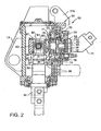
- the split tool tamper 10 of the present invention includes a motor 11, such as a hydraulic motor, a conversion device 50, and a single tool shaft 90.
- the split tool tamper 10 may be pivotally attached to a generally vertical frame 12.
- the frame 12 may be attached to vertical translation means, such as a hydraulic piston 13 (Fig. 4).
- the vertical translation means may be coupled to a railroad car (not shown) or other suitable vehicle which may travel over a railroad ballast bed.
- the conversion device 50 is enclosed with in a housing 20.
- the split tool tamper 10 further includes a tool shaft 90 and a tamping tool 100.
- the tool shaft 90 is enclosed within output shaft housing 91.
- the housing 20 may include a lower mounting protrusion 14 and an upper mounting protrusion 24.
- lower mounting protrusion 14 may be a pair of tabs 14a, 14b (Fig. 3).
- Each tab 14a, 14b includes an opening 15a, 15b therethrough.
- Frame 12 includes a pair of mounting tabs 16a, 16b which are sized and spaced to correspond to housing tabs 14a, 14b.
- Each frame tab includes an opening therethrough.
- a pin 17a, 17b having a threaded end 18a, 18b passes through each frame tab 16a, 16b, and housing tab 14a, 14b.
- a nut 19a, 19b engages threaded ends 18a, 18b thereby pivotally mounting housing 20 to frame 12.
- the housing 20 is further connected to frame 12 at upper mounting protrusion 24.
- Upper mounting protrusion 24 may have tabs 24a, 24b each having an opening 25a, 25b therethrough.
- Frame 12 includes an upper frame tab 26 proximal to the upper mounting protrusion 24.
- the upper frame tab 26 includes an opening therethrough.
- An extension member 30, such as a hydraulic cylinder, extends between frame 12 and upper mounting protrusion 24.
- the extension member 30 includes a first coupling end 31 and second coupling end 32.
- the coupling ends 31, 32 may have an opening for a pin.
- the extension member 30 may be coupled to frame 12 by mounting pins 33, 34. As shown, mounting pin 33 is disposed through the opening in the first coupling end 31 and tab 26.
- the other mounting pin 34 is disposed in the second coupling end 32 and openings 25a, 25b.
- the extension member 30 has a first, closed position and a second, maximum extended position.
- the split tool tamper may be angled 0 to 13 degrees from vertical by extending the extension member 30.
- extension member In the first, closed position, extension member is structured to align tool shaft 90 substantially parallel to frame 12.
- extension member 30 In the second, extended position, extension member 30 causes housing 20 to rotate clockwise, as shown in Fig. 1, about mounting pins 17a, 17b so that tool shaft 90 is angled downwardly and inwardly relative to frame 12.
- the extension member may be coupled to a hydraulic system 38 which can cause extension member 30 to move between the first and the second position approximately every three seconds.
- Motor 11 includes a rotating output shaft 40 having a generally horizontal axis when the extension member 30 is in the first position.
- Rotating output shaft 40 is connected to conversion device 50.
- motor 11 rotates output shaft 40 around the generally horizontal axis.
- the motor 11 will rotate output shaft 40 at about 3000 R.P.M.
- the motor 11 in conjunction with conversion device 50 creates a reciprocating rotational motion in tool shaft 90.
- conversion device 50 which is connected to the rotating output shaft 40, includes an eccentric hub 52 having a generally horizontal axis and an eccentric hub mounting means, such as a first roller bearing 54 and a second roller bearing 55.
- the eccentric hub mounting means extends between housing 20 and outer bearing surface 70 (described below).
- the eccentric hub 52 of the conversion device 50 is generally cup-shaped having a disk 56 with a sidewall 57 extending from the perimeter of the disk 56.
- the sidewall 57 forms a recess 60 having an open face.
- Disk 56 is generally circular and includes a medial opening 62 therethrough so that shaft 40 can pass through it.
- Sidewall 57 includes a thick portion 64 and a thin portion 66.
- Thick portion 64 is located on the opposite side of disk 56 from thin portion 66.
- Sidewall 57 gradually decreases in thickness from thick portion 64 to thin portion 66.
- the sidewall's 57 outer surface is an outer bearing surface 70.
- the sidewall 57 also includes an inner wall which forms an inner bearing surface 71.
- the conversion device 50 further includes a spherical roller bearing 72.
- Spherical roller bearing 72 is a toroid having a medial opening 74 and an outer bearing surface 76. Roller bearing 72 is disposed within the eccentric hub recess 60. Roller bearing outer surface 76 contacts sidewall inner bearing surface 71. Spherical roller bearing 72 also includes an inner bearing surface 78.
- the conversion device 50 further includes a yoke 80 having a shaft 81, a vertical cavity 82 and a horizontal pin opening 83.
- Shaft 81 includes an outer bearing surface 86.
- Shaft 81 is disposed within roller bearing medial hole 74 with bearing surface 86 contacting roller bearing inner bearing surface 78.
- An attachment pin 84 is disposed in horizontal pin opening 83.
- Tool shaft 90 includes an upper end 92 and a lower end 94.
- Upper end 92 forms a mounting bracket 96 having an opening 97 therethrough.
- Tool shaft opening 97 is sized to engage attachment pin 84.
- Shaft lower end 94 includes a tamping tool 100.
- the tamping tool 100 has a lower end 101 that is structured to contact railroad ballast.
- Tool shaft 90 is supported in housing 20 by two spaced bearings 98.
- Tool shaft 90 is supported by bearings 98 so that tool shaft 90 extends generally perpendicular to rotating axle 40.
- the split tool tamper 10 is pivotably mounted on a frame 12 by mounting pins 17a and 17b.
- the frame 12 is coupled by a hydraulic piston to railroad vehicle (not shown) so that the axis of mounting pins 17a and 17b extend generally in a direction perpendicular to the direction of the railroad rail.
- extension member 30 When extension member 30 is in the closed position, the axis of rotating axle 40 extends in a direction generally normal to the axis of mounting pins 17a and 17b .
- the axis of eccentric hub 52 which is attached to rotating axle 40, and roller bearing 72, which is disposed inside eccentric hub 52, also extend in a direction generally normal to the axis of mounting pins 17a and 17b.
- the shaft 81 is disposed within roller bearing 72, extending in a direction generally normal to the axis of mounting pins 17a and 17b.
- the yoke 80 may be positioned so that the axis of attachment pin 84 extends in a direction generally parallel to the axis of mounting pins 17a and 17b.
- Mounting bracket 96 is coupled to the conversion device 50 by passing attachment pin 84 through horizontal pin opening 83.
- motor 11 provides a rotational force to rotating axle 40.
- Rotating axle 40 rotates eccentric hub 52.
- the axis of eccentric hub 52 is reciprocated horizontally and vertically as axle 40 is rotated.
- Roller bearing 72 which is disposed within eccentric hub 52, is thereby reciprocated horizontally and vertically.
- the reciprocal motion of eccentric hub 52 is transferred from the roller bearing 72 to the shaft 81, yoke 80 and attachment pin 84, into tool shaft 90.
- the vertical position of tool shaft 90 is maintained by bearings 98.
- yoke 80 will pivot reciprocate in a vertical direction about pin 84.
- the horizontal reciprocation is transferred to tool shaft 90 as described below.
- the location of the eccentric hub sidewall thick portion 64 will correlate to a clock's hour hand.
- sidewall thick portion 64 is in the upper most position.
- the eccentric hub 52 is in the twelve o'clock position.
- the axis of shaft 81 and the axis of axle 40, when seen from above are aligned.
- the axis of shaft 81 when seen from above, is offset approximately 2.5 degrees in a counter-clockwise direction from the axis of axle 40, as measured from the axis of shaft 90.
- the motor may be a hydraulic, pneumatic or other type of motor. Accordingly, the particular arrangements disclosed are meant to be illustrative only and not limiting as to the scope of invention which is to be given the full breadth of the claims appended.
- “coupled,” means a linkage, direct or indirect, so long as a linkage occurs.
Landscapes
- Engineering & Computer Science (AREA)
- Architecture (AREA)
- Civil Engineering (AREA)
- Structural Engineering (AREA)
- Transmission Devices (AREA)
- Road Paving Machines (AREA)
- Machines For Laying And Maintaining Railways (AREA)
- Conveying And Assembling Of Building Elements In Situ (AREA)
- Investigation Of Foundation Soil And Reinforcement Of Foundation Soil By Compacting Or Drainage (AREA)
- Manufacture Of Motors, Generators (AREA)
Claims (6)
- Getrenntes Stopfwerkzeug (10), welches folgendes aufweist:(a) einen Rahmen (12);(b) einen Motor (11) an dem Rahmen (12), um eine im wesentlichen hin- und hergehende Drehbewegung zu erzeugen;(c) Mittel einer Werkzeugwelle (90), die an dem Rahmen (12) gelagert sind, wobei die Mittel einer Werkzeugwelle (90) vom Motor (11) angetrieben werden, um die hin- und hergehende Drehbewegung auszuführen, und wobei die Mittel einer Werkzeugwelle (90) ein erstes und ein zweites Ende aufweisen, von denen das erste Ende an den Motor (11) über eine Umformeinrichtung (50) angekuppelt ist, um die Drehbewegung des Motors in eine oszillierende Drehbewegung umzuformen;(d) eine Stopfwerkzeugeinrichtung (100) am zweiten Ende der Mittel einer Werkzeugwelle (90);
dadurch gekennzeichnet, dass(e) das Mittel einer Werkzeugwelle (90) als einzige Werkzeugwelle vorgesehen ist und die Stopfwerkzeugeinrichtung (100) ein einziges Stopfwerkzeug aufweist, wobei die einzige Werkzeugwelle dazu ausgebildet ist, ein einziges Stopfwerkzeug (100) an ihrem zweiten Ende anzutreiben; wogegen(f) der Motor (11) einerseits durch ein im wesentlichen horizontales Drehgelenk (17a, 17b) schwenkbar und anderseits durch ein am Motor (11) in einer Entfernung vom Drehgelenk (17a, 17b) angebrachtes Streckorgan (30) mit dem Rahmen (12) gekuppelt ist, so dass das Streckorgan (30) dazu im Stande ist, den das einzige Werkzeug antreibenden Motor (11), die einzige Werkzeugwelle (90) und das einzige Stopfwerkzeug (100) um dieses Drehgelenk (17a, 17b) zu verschwenken. - Getrenntes Stopfwerkzeug nach Anspruch 1, dadurch gekennzeichnet, dass der Motor (11) ein Gehäuse (91) und eine Drehwelle (40) aufweist, und dass die Umformeinrichtung (50) folgendes aufweist:- eine exzentrische Nabe (52) mit mittiger Öffnung (62) und kreisförmiger Seitenwand (57);- welche exzentrische Seitenwand (57) eine exzentrische Ausnehmung (60) besitzt;- und die Motorwelle (40) durch die mittige Öffnung (62) hindurch verläuft und mit der Nabe (62) gekuppelt ist;- ein Joch (80) mit einer Welle (81) und einem Schwenkbolzen (84);- wovon die Welle (81) des Joches in der exzentrischen Ausnehmung (60) der Nabe angeordnet ist;- ein Bügel (96), der am ersten Ende der Werkzeugwelle (81) angeordnet ist;- welcher Bügel (96) mit dem Schwenkbolzen (84) des Joches gekuppelt ist; und- wobei die einzige Werkzeugwelle (90) durch mindestens zwei Lager (98) in dem Gehäuse (91) gelagert ist.
- Getrenntes Stopfwerkzeug nach Anspruch 2, dadurch gekennzeichnet, dass die Umformeinrichtung (50) auch folgendes aufweist:- ein Kugellager /72) mit einer Lagerfläche (76) und einer mittigen Öffnung (74);- welches Kugellager (72) in der exzentrischen Ausnehmung (60) der Nabe angeordnet ist; und- wobei die Welle (81) des Joches in der mittigen Öffnung (74) des Kugellagers angeordnet ist.
- Getrenntes Stopfwerkzeug nach einem der vorhergehenden Ansprüche, dadurch gekennzeichnet, dass sich die einzige Werkzeugwelle (90) im wesentlichen senkrecht zur Drehwelle (40) des Motors (11) erstreckt.
- Getrenntes Stopfwerkzeug nach einem der Ansprüche 2 bis 4, dadurch gekennzeichnet, dass es ferner ein erstes, zwischen dem Gehäuse (20) und einer Lagerfläche (70) der exzentrischen Nabe (52) angeordnetes Rollenlager (54) und/oder ein Kugellager (72) und/oder ein zwischen einer äußeren Lagerfläche (86) der Welle (81) des Joches und einer inneren Lagerfläche (79) der Seitenwand (57) gelegenes Kugellager (72) aufweist.
- Getrenntes Stopfwerkzeug nach einem der Ansprüche 2 bis 5, dadurch gekennzeichnet, dass die Achse des Schwenkbolzens (84) sich im wesentlichen senkrecht zur Achse der Welle (81) des Joches, und vorzugsweise im wesentlichen senkrecht zur Achse des Mittels einer Werkzeugwelle (90), erstreckt.
Priority Applications (1)
| Application Number | Priority Date | Filing Date | Title |
|---|---|---|---|
| EP06003299A EP1676958B1 (de) | 2000-07-12 | 2001-06-27 | Getriebe zum umwandeln von Dreh- in Schwingende Bewegung |
Applications Claiming Priority (2)
| Application Number | Priority Date | Filing Date | Title |
|---|---|---|---|
| US09/614,999 US6386114B1 (en) | 2000-07-12 | 2000-07-12 | Single shaft tamper with reciprocating rotational output |
| US614999 | 2000-07-12 |
Related Child Applications (1)
| Application Number | Title | Priority Date | Filing Date |
|---|---|---|---|
| EP06003299A Division EP1676958B1 (de) | 2000-07-12 | 2001-06-27 | Getriebe zum umwandeln von Dreh- in Schwingende Bewegung |
Publications (3)
| Publication Number | Publication Date |
|---|---|
| EP1172480A2 EP1172480A2 (de) | 2002-01-16 |
| EP1172480A3 EP1172480A3 (de) | 2003-07-16 |
| EP1172480B1 true EP1172480B1 (de) | 2007-01-10 |
Family
ID=24463575
Family Applications (2)
| Application Number | Title | Priority Date | Filing Date |
|---|---|---|---|
| EP01115430A Expired - Lifetime EP1172480B1 (de) | 2000-07-12 | 2001-06-27 | Getrenntes Stopfwerkzeug |
| EP06003299A Expired - Lifetime EP1676958B1 (de) | 2000-07-12 | 2001-06-27 | Getriebe zum umwandeln von Dreh- in Schwingende Bewegung |
Family Applications After (1)
| Application Number | Title | Priority Date | Filing Date |
|---|---|---|---|
| EP06003299A Expired - Lifetime EP1676958B1 (de) | 2000-07-12 | 2001-06-27 | Getriebe zum umwandeln von Dreh- in Schwingende Bewegung |
Country Status (5)
| Country | Link |
|---|---|
| US (1) | US6386114B1 (de) |
| EP (2) | EP1172480B1 (de) |
| DE (2) | DE60125871T2 (de) |
| ES (1) | ES2307243T3 (de) |
| PT (1) | PT1676958E (de) |
Cited By (1)
| Publication number | Priority date | Publication date | Assignee | Title |
|---|---|---|---|---|
| AU2003203686B2 (en) * | 2002-04-12 | 2009-09-17 | Harsco Technologies Corporation | Conversion device for converting a rotational motion into a reciprocal motion |
Families Citing this family (12)
| Publication number | Priority date | Publication date | Assignee | Title |
|---|---|---|---|---|
| US6978718B2 (en) * | 2004-03-04 | 2005-12-27 | Seyrlehner Georg J | Tamping device and method of tamping a railroad track's ballast |
| RU2337201C1 (ru) * | 2007-07-10 | 2008-10-27 | Государственное образовательное учреждение высшего профессионального образования "Петербургский государственный университет путей сообщения" | Электрошпалоподбойка |
| CN103015275B (zh) * | 2011-09-28 | 2016-01-20 | 安阳振动器有限责任公司 | 便携式捣固镐 |
| US9731324B2 (en) * | 2013-09-25 | 2017-08-15 | Nordco Inc. | Drive for railroad ballast tamper apparatus |
| CN104846705A (zh) * | 2015-04-29 | 2015-08-19 | 柳州三农科技有限公司 | 一种电动软轴捣固机的使用方法 |
| USD789994S1 (en) | 2015-08-05 | 2017-06-20 | Nordco Inc. | Tamper tool |
| AU2016204901A1 (en) * | 2015-08-10 | 2017-03-02 | Nordco Inc. | Tamper Tool and Associated Holder |
| AU2016332560B2 (en) * | 2015-10-01 | 2021-07-29 | Harsco Technologies LLC | Hybrid continuous indexing tamper vehicle |
| AT517999B1 (de) | 2015-11-20 | 2018-05-15 | Plasser & Theurer Export Von Bahnbaumaschinen Gmbh | Stopfaggregat und Verfahren zum Stopfen eines Gleises |
| AT520267B1 (de) * | 2017-08-08 | 2020-02-15 | Plasser & Theurer Export Von Bahnbaumaschinen Gmbh | Stopfaggregat zum Unterstopfen von Schwellen eines Gleises |
| AT523825B1 (de) * | 2020-07-03 | 2021-12-15 | Plasser & Theurer Export Von Bahnbaumaschinen Gmbh | Maschine und Verfahren mit einem Stopfaggregat |
| CN116791895B (zh) * | 2022-04-29 | 2025-08-19 | 中国电建集团华东勘测设计研究院有限公司 | 一种地下室承台混凝土分层浇筑振捣装置及其使用方法 |
Family Cites Families (19)
| Publication number | Priority date | Publication date | Assignee | Title |
|---|---|---|---|---|
| US2201023A (en) * | 1940-05-14 | Railroad tie tamping machine | ||
| US798416A (en) * | 1904-02-15 | 1905-08-29 | Jackson Electric Drill And Supply Company | Rock-drill. |
| US1464570A (en) * | 1920-05-17 | 1923-08-14 | Hage Rudolf Alexander | Riveting, chiseling, and rock-drilling hammer |
| US1399387A (en) * | 1921-04-11 | 1921-12-06 | Jackson Corwill | Tamper and like impact-tool |
| US1621103A (en) * | 1926-01-20 | 1927-03-15 | Ajax Electric Hammer Corp | Power-driven hammer or riveter |
| US1932723A (en) * | 1928-09-04 | 1933-10-31 | Hugh S Brown | Vibratory tool |
| US2079909A (en) * | 1934-09-26 | 1937-05-11 | Jackson Corwill | Vibrating motor |
| AT236434B (de) * | 1961-08-16 | 1964-10-26 | Plasser Bahnbaumasch Franz | Gleisstopfmaschine |
| AT315227B (de) * | 1969-08-08 | 1974-05-10 | Plasser Bahnbaumasch Franz | Stopfwerkzeug für Gleisstopfmaschinen |
| US3736879A (en) * | 1971-05-13 | 1973-06-05 | Jackson Vibrators | Ballast tamper blade |
| DE2236371C2 (de) * | 1972-07-25 | 1977-02-24 | Losenhansen Maschinenbau Ag | Handgeführtes stampfgerät |
| US3901159A (en) * | 1974-03-21 | 1975-08-26 | Canron Inc | Tamping tool head |
| DE2441180C3 (de) * | 1974-08-28 | 1981-06-11 | Koehring Gmbh - Bomag Division, 5407 Boppard | Von Hand geführter Vibrationsstampfer |
| AT343168B (de) | 1976-02-20 | 1978-05-10 | Plasser Bahnbaumasch Franz | Gleisstopfmaschine mit wenigstens einem hohenverstellbaren stopfaggregat |
| AT350097B (de) * | 1977-02-04 | 1979-05-10 | Plasser Bahnbaumasch Franz | Maschine zum unterstopfen der querschwellen eines gleises |
| PL163768B1 (pl) | 1989-04-18 | 1994-05-31 | Plasser Bahnbaumasch Franz | Maszyna jezdna do podbijania toru PL |
| US5363711A (en) * | 1991-04-22 | 1994-11-15 | Osada Research Institute, Ltd. | Power transmission device |
| ATE139282T1 (de) | 1992-08-12 | 1996-06-15 | Plasser Bahnbaumasch Franz | Gleisstopfmaschine zum unterstopfen von weichen und kreuzungen eines gleises |
| ES2101605T3 (es) * | 1994-08-09 | 1997-07-01 | Plasser Bahnbaumasch Franz | Grupo de bateado para maquinas bateadoras de vias ferreas, para el entrebateado de dos traviesas inmediatamente contiguas. |
-
2000
- 2000-07-12 US US09/614,999 patent/US6386114B1/en not_active Expired - Lifetime
-
2001
- 2001-06-27 DE DE60125871T patent/DE60125871T2/de not_active Expired - Lifetime
- 2001-06-27 EP EP01115430A patent/EP1172480B1/de not_active Expired - Lifetime
- 2001-06-27 PT PT06003299T patent/PT1676958E/pt unknown
- 2001-06-27 ES ES06003299T patent/ES2307243T3/es not_active Expired - Lifetime
- 2001-06-27 EP EP06003299A patent/EP1676958B1/de not_active Expired - Lifetime
- 2001-06-27 DE DE60135040T patent/DE60135040D1/de not_active Expired - Lifetime
Cited By (1)
| Publication number | Priority date | Publication date | Assignee | Title |
|---|---|---|---|---|
| AU2003203686B2 (en) * | 2002-04-12 | 2009-09-17 | Harsco Technologies Corporation | Conversion device for converting a rotational motion into a reciprocal motion |
Also Published As
| Publication number | Publication date |
|---|---|
| EP1676958B1 (de) | 2008-07-23 |
| DE60125871T2 (de) | 2007-04-19 |
| EP1172480A2 (de) | 2002-01-16 |
| EP1172480A3 (de) | 2003-07-16 |
| EP1676958A1 (de) | 2006-07-05 |
| ES2307243T3 (es) | 2008-11-16 |
| DE60125871D1 (de) | 2007-02-22 |
| PT1676958E (pt) | 2008-08-06 |
| DE60135040D1 (de) | 2008-09-04 |
| US6386114B1 (en) | 2002-05-14 |
Similar Documents
| Publication | Publication Date | Title |
|---|---|---|
| EP1172480B1 (de) | Getrenntes Stopfwerkzeug | |
| WO1999005363A1 (en) | Vibratory pavement breaker | |
| US6581524B1 (en) | Conversion device for converting a rotational motion into a reciprocal motion | |
| ID19837A (id) | Penggiling tumbukan | |
| CN208530583U (zh) | 电钩推送装置及具有其的连接车钩、轨道车辆 | |
| US4218978A (en) | Apparatus for tamping or packing the bed of railway tracks | |
| CA2237012A1 (en) | Independent brake handle assembly | |
| CN1214391A (zh) | 捣固机组 | |
| CN1091223C (zh) | 密闭旋转式压缩机上的滑动排出阀 | |
| CN112112008B (zh) | 含可移动支点横移机构的养护工作装置框架及作业方法 | |
| JPH11313503A (ja) | 整畦機 | |
| EP1134883A3 (de) | Vibrationsmotoren | |
| CN214116242U (zh) | 一种公路桥梁碎路机 | |
| JP3895701B2 (ja) | 鉄道分岐器用エスケープクランク | |
| CN210657823U (zh) | 一种含偏心夹持机构的捣固装置 | |
| CN100376380C (zh) | 机械锻压机 | |
| CN113562015A (zh) | 一种扫石器 | |
| CN220013482U (zh) | 一种转闸机芯 | |
| KR200169886Y1 (ko) | 컴프레서용 구동장치 | |
| JPH0322294Y2 (de) | ||
| CN208127052U (zh) | 一种防爆开关隔离推进装置 | |
| CN202705870U (zh) | 熨平板压实梁、熨平板和摊铺机 | |
| CN2033015U (zh) | 四连杆铰接式振动夯 | |
| CN2164596Y (zh) | 低压转换开关操作机构 | |
| SU1523620A1 (ru) | Скалыватель уплотненного снега и льда с дорожных покрытий |
Legal Events
| Date | Code | Title | Description |
|---|---|---|---|
| PUAI | Public reference made under article 153(3) epc to a published international application that has entered the european phase |
Free format text: ORIGINAL CODE: 0009012 |
|
| AK | Designated contracting states |
Kind code of ref document: A2 Designated state(s): AT BE CH CY DE DK ES FI FR GB GR IE IT LI LU MC NL PT SE TR |
|
| AX | Request for extension of the european patent |
Free format text: AL;LT;LV;MK;RO;SI |
|
| PUAL | Search report despatched |
Free format text: ORIGINAL CODE: 0009013 |
|
| AK | Designated contracting states |
Designated state(s): AT BE CH CY DE DK ES FI FR GB GR IE IT LI LU MC NL PT SE TR |
|
| AX | Request for extension of the european patent |
Extension state: AL LT LV MK RO SI |
|
| 17P | Request for examination filed |
Effective date: 20031016 |
|
| 17Q | First examination report despatched |
Effective date: 20031117 |
|
| AKX | Designation fees paid |
Designated state(s): DE ES GB IT PT |
|
| GRAP | Despatch of communication of intention to grant a patent |
Free format text: ORIGINAL CODE: EPIDOSNIGR1 |
|
| GRAS | Grant fee paid |
Free format text: ORIGINAL CODE: EPIDOSNIGR3 |
|
| RAP1 | Party data changed (applicant data changed or rights of an application transferred) |
Owner name: HARSCO CORPORATION |
|
| GRAA | (expected) grant |
Free format text: ORIGINAL CODE: 0009210 |
|
| AK | Designated contracting states |
Kind code of ref document: B1 Designated state(s): DE ES GB IT PT |
|
| REG | Reference to a national code |
Ref country code: GB Ref legal event code: FG4D |
|
| REF | Corresponds to: |
Ref document number: 60125871 Country of ref document: DE Date of ref document: 20070222 Kind code of ref document: P |
|
| PG25 | Lapsed in a contracting state [announced via postgrant information from national office to epo] |
Ref country code: ES Free format text: LAPSE BECAUSE OF FAILURE TO SUBMIT A TRANSLATION OF THE DESCRIPTION OR TO PAY THE FEE WITHIN THE PRESCRIBED TIME-LIMIT Effective date: 20070421 |
|
| PG25 | Lapsed in a contracting state [announced via postgrant information from national office to epo] |
Ref country code: PT Free format text: LAPSE BECAUSE OF FAILURE TO SUBMIT A TRANSLATION OF THE DESCRIPTION OR TO PAY THE FEE WITHIN THE PRESCRIBED TIME-LIMIT Effective date: 20070611 |
|
| PLBE | No opposition filed within time limit |
Free format text: ORIGINAL CODE: 0009261 |
|
| STAA | Information on the status of an ep patent application or granted ep patent |
Free format text: STATUS: NO OPPOSITION FILED WITHIN TIME LIMIT |
|
| 26N | No opposition filed |
Effective date: 20071011 |
|
| PG25 | Lapsed in a contracting state [announced via postgrant information from national office to epo] |
Ref country code: IT Free format text: LAPSE BECAUSE OF NON-PAYMENT OF DUE FEES Effective date: 20090627 |
|
| PGRI | Patent reinstated in contracting state [announced from national office to epo] |
Ref country code: IT Effective date: 20110616 |
|
| REG | Reference to a national code |
Ref country code: DE Ref legal event code: R082 Ref document number: 60125871 Country of ref document: DE Representative=s name: MURGITROYD & COMPANY, DE |
|
| PGFP | Annual fee paid to national office [announced via postgrant information from national office to epo] |
Ref country code: DE Payment date: 20200629 Year of fee payment: 20 |
|
| PGFP | Annual fee paid to national office [announced via postgrant information from national office to epo] |
Ref country code: IT Payment date: 20200619 Year of fee payment: 20 Ref country code: GB Payment date: 20200629 Year of fee payment: 20 |
|
| REG | Reference to a national code |
Ref country code: DE Ref legal event code: R071 Ref document number: 60125871 Country of ref document: DE |
|
| REG | Reference to a national code |
Ref country code: GB Ref legal event code: PE20 Expiry date: 20210626 |
|
| PG25 | Lapsed in a contracting state [announced via postgrant information from national office to epo] |
Ref country code: GB Free format text: LAPSE BECAUSE OF EXPIRATION OF PROTECTION Effective date: 20210626 |