EP1172547A2 - Système d'admission pour un véhicule - Google Patents
Système d'admission pour un véhicule Download PDFInfo
- Publication number
- EP1172547A2 EP1172547A2 EP01115421A EP01115421A EP1172547A2 EP 1172547 A2 EP1172547 A2 EP 1172547A2 EP 01115421 A EP01115421 A EP 01115421A EP 01115421 A EP01115421 A EP 01115421A EP 1172547 A2 EP1172547 A2 EP 1172547A2
- Authority
- EP
- European Patent Office
- Prior art keywords
- motor vehicle
- intake system
- additional opening
- intake
- passenger compartment
- Prior art date
- Legal status (The legal status is an assumption and is not a legal conclusion. Google has not performed a legal analysis and makes no representation as to the accuracy of the status listed.)
- Granted
Links
Images

Classifications
-
- F—MECHANICAL ENGINEERING; LIGHTING; HEATING; WEAPONS; BLASTING
- F02—COMBUSTION ENGINES; HOT-GAS OR COMBUSTION-PRODUCT ENGINE PLANTS
- F02M—SUPPLYING COMBUSTION ENGINES IN GENERAL WITH COMBUSTIBLE MIXTURES OR CONSTITUENTS THEREOF
- F02M35/00—Combustion-air cleaners, air intakes, intake silencers, or induction systems specially adapted for, or arranged on, internal-combustion engines
- F02M35/16—Combustion-air cleaners, air intakes, intake silencers, or induction systems specially adapted for, or arranged on, internal-combustion engines characterised by use in vehicles
- F02M35/161—Arrangement of the air intake system in the engine compartment, e.g. with respect to the bonnet or the vehicle front face
-
- F—MECHANICAL ENGINEERING; LIGHTING; HEATING; WEAPONS; BLASTING
- F02—COMBUSTION ENGINES; HOT-GAS OR COMBUSTION-PRODUCT ENGINE PLANTS
- F02M—SUPPLYING COMBUSTION ENGINES IN GENERAL WITH COMBUSTIBLE MIXTURES OR CONSTITUENTS THEREOF
- F02M35/00—Combustion-air cleaners, air intakes, intake silencers, or induction systems specially adapted for, or arranged on, internal-combustion engines
- F02M35/10—Air intakes; Induction systems
- F02M35/10006—Air intakes; Induction systems characterised by the position of elements of the air intake system in direction of the air intake flow, i.e. between ambient air inlet and supply to the combustion chamber
- F02M35/10013—Means upstream of the air filter; Connection to the ambient air
-
- F—MECHANICAL ENGINEERING; LIGHTING; HEATING; WEAPONS; BLASTING
- F02—COMBUSTION ENGINES; HOT-GAS OR COMBUSTION-PRODUCT ENGINE PLANTS
- F02M—SUPPLYING COMBUSTION ENGINES IN GENERAL WITH COMBUSTIBLE MIXTURES OR CONSTITUENTS THEREOF
- F02M35/00—Combustion-air cleaners, air intakes, intake silencers, or induction systems specially adapted for, or arranged on, internal-combustion engines
- F02M35/12—Intake silencers ; Sound modulation, transmission or amplification
- F02M35/1205—Flow throttling or guiding
- F02M35/1227—Flow throttling or guiding by using multiple air intake flow paths, e.g. bypass, honeycomb or pipes opening into an expansion chamber
-
- F—MECHANICAL ENGINEERING; LIGHTING; HEATING; WEAPONS; BLASTING
- F02—COMBUSTION ENGINES; HOT-GAS OR COMBUSTION-PRODUCT ENGINE PLANTS
- F02M—SUPPLYING COMBUSTION ENGINES IN GENERAL WITH COMBUSTIBLE MIXTURES OR CONSTITUENTS THEREOF
- F02M35/00—Combustion-air cleaners, air intakes, intake silencers, or induction systems specially adapted for, or arranged on, internal-combustion engines
- F02M35/12—Intake silencers ; Sound modulation, transmission or amplification
- F02M35/1255—Intake silencers ; Sound modulation, transmission or amplification using resonance
- F02M35/1266—Intake silencers ; Sound modulation, transmission or amplification using resonance comprising multiple chambers or compartments
-
- F—MECHANICAL ENGINEERING; LIGHTING; HEATING; WEAPONS; BLASTING
- F02—COMBUSTION ENGINES; HOT-GAS OR COMBUSTION-PRODUCT ENGINE PLANTS
- F02M—SUPPLYING COMBUSTION ENGINES IN GENERAL WITH COMBUSTIBLE MIXTURES OR CONSTITUENTS THEREOF
- F02M35/00—Combustion-air cleaners, air intakes, intake silencers, or induction systems specially adapted for, or arranged on, internal-combustion engines
- F02M35/12—Intake silencers ; Sound modulation, transmission or amplification
- F02M35/1294—Amplifying, modulating, tuning or transmitting sound, e.g. directing sound to the passenger cabin; Sound modulation
Definitions
- the invention relates to an intake system for a motor vehicle, which in addition to Intake opening for the combustion air has an additional opening, which over a branch communicates with the intake system, according to the preamble of the claim 1.
- the invention also relates to a motor vehicle in which this Intake system is used according to the type of patent claim 4.
- the acoustic measure described is universal for damping noise emissions to be used in the intake or exhaust system.
- the requirements to effectively influence the noise emissions of motor vehicles however, often more targeted measures than using broadband Damping effects.
- the object of the invention is therefore an intake system for an internal combustion engine to create, with the help of which optimally influences the intake noise can be. This object is achieved by the features of claim 1 and of claim 4 solved.
- the intake system according to the invention is characterized in that the additional opening, which is attached to the junction, is aligned such that at installation of the intake system in the engine compartment of the internal combustion engine, the muzzle sound, which starts from the additional opening, primarily to stimulate the Passenger cell leads.
- priority is meant that the arrangement of the additional opening is aimed at an acoustic effect that can be achieved in the passenger compartment.
- the intake noise can be independent are influenced by the driving noise of the vehicle emitted into the environment.
- acoustic effects can be achieved, which dampen the intake noise in the passenger compartment, e.g. B. lead by phase-shifted excitation can.
- the muzzle sound of the additional opening can also be used to to influence the characteristics of the interior noise.
- Combustion air can enter through the additional opening as through the intake opening Suction system.
- An introduction in front of the air filter is therefore a good idea the combustion air sucked in through the additional opening is also filtered becomes.
- the branch is also arranged in the clean air area of the intake system possible if the air sucked in through the additional opening is separate is cleaned.
- the intake system can contain other components, their use in the intake tract the internal combustion engine is common.
- a suction pipe and one Actuator e.g. B. to call a throttle valve.
- the junction can also consist of several branches and also have several additional openings. These have different acoustic effects, which taken together lead to the desired sound pattern of the intake noise.
- the acoustic devices can have no significant effect on the Suction behavior of the internal combustion engine can be arranged.
- the suction characteristic is primarily determined by the intake system with the intake opening. Only a secondary air flow is transported through the branch, so that a change in the geometry to adapt the intake noise to the desired characteristic does not significantly affect. In particular, larger ones Avoid performance losses in the intake tract due to acoustic measures.
- the branch can be made with the aid of a plug connection be attached to the intake system.
- This enables better customization the intake system z. B. to different types of internal combustion engines.
- the suction characteristic can be changed by changing the attached branch adapt to the individual case. Also customer requests, e.g. B. for a sportier Sound of the internal combustion engine can be made using different branches be taken into account.
- Another variant of the invention proposes to construct the branch modularly.
- the various modules have connection points, so that the Junction can be assembled. With a small number of identical parts can be created in this way a modular system, which in individual cases an optimal adaptation of the branch to the acoustic framework allows. If several additional openings are used, must these are not all geared towards giving priority to the passenger compartment become. Rather, acoustic effects can also be used if these differ Have alignments.
- the branch can be opened be installed in different ways in the engine compartment of the motor vehicle.
- a The first possibility is to align the additional opening to a part of the Body, which enables good sound conduction to the passenger compartment.
- the wheel arch of the front wheel, which is nearby should be mentioned of the intake system. Due to the sound conduction, this is in the passenger compartment located volumes excited to vibrations, which with a suitable design the branch to the desired acoustic effects that result from the vehicle occupants are noticed.
- Another option is to open the additional opening directly onto the partition between the passenger compartment and the engine compartment.
- the muzzle sound of the additional opening then acts directly on this partition of the engine compartment, causing this is excited to vibrate, which is in the interior of the passenger compartment procreate.
- the additional opening is also possible for the additional opening to align with a reflective surface. This is part of the engine compartment to understand and leads to a deflection of the muzzle sound in the direction the passenger compartment, whereby the acoustic effects mentioned are achieved.
- the additional opening communicates directly or indirectly with the volume of the passenger compartment. It is advantageous here Connect the additional opening to the fresh air supply for the passenger compartment. This can e.g. B. via the duct system of ventilation or air conditioning. By the channel system becomes the muzzle sound emanating from the additional opening passed into the passenger compartment, which has the acoustic effects already described brings itself.
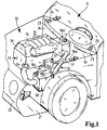
- a motor vehicle with an engine compartment 10 and a passenger compartment 11 has an intake system 12, which supplies an internal combustion engine 13 with intake air.
- the Intake system leads from an intake opening 14 for combustion air to the cylinder side Exits 15 attached to a cylinder head 16 of the engine 13 are.
- Various branches 17 branch off from the intake system 12, which have additional openings 18a to d are provided, so that combustion air through these additional openings can be sucked in.
- the additional opening 18a is directed directly at a partition 19, which is the passenger compartment 11 separates from the engine compartment 10.
- the one starting from the additional opening 18a Muzzle sound is symbolically represented by an arrow. This affects directly the partition, creating a sound transmission between the engine compartment and passenger compartment he follows. In this respect, the additional opening 18a directly influences that in the passenger compartment perceivable noise of the internal combustion engine.
- the additional opening 18b is directed to a wheel arch 20.
- the muzzle sound also indicated by an arrow, leads to a vibration excitation of the Wheel arch, which thus transmits the muzzle sound to the passenger compartment.
- Another possibility is the alignment of the additional opening on a reflection surface 21. This is in the embodiment by an underbody paneling formed on a front apron 22 of the motor vehicle. Through the reflective surface the sound is reflected in the direction of the passenger compartment 11 (indicated by a corresponding arrow). This also reduces the noise in the passenger compartment influence.
- a last possibility is to connect the additional opening 18d to one Fresh air supply 23 of the motor vehicle. Through ventilation slots 24 in the passenger compartment, but also by vibrating the duct system Fresh air supply 23, the mouth noise of the additional opening 18d in the Passenger cell transported.
- the different orientations can be used to influence the intake noise the additional opening 18a to d provided individually, in groups or together become.
- the overall effect on the intake noise prevailing in the passenger compartment must be determined experimentally.
- certain frequency ranges are canceled or their vibration characteristics are influenced in this way that they are less in the subjective perception of vehicle occupants attract attention.
- a kit for a branch 17 which consists of modules is composed.
- the modules have connection points 25, via which they communicate with each other.
- the connection points are shown schematically.
- the modules can be freely connected to one another combine. Possible configurations of the modules are covers 30 for side openings 31, which, for. B. can be used to connect Lambda Virtel tubes, Resonance rooms 33 and line sections 34, which with additional openings 18a, b can be provided.
Landscapes
- Engineering & Computer Science (AREA)
- Chemical & Material Sciences (AREA)
- Combustion & Propulsion (AREA)
- Mechanical Engineering (AREA)
- General Engineering & Computer Science (AREA)
- Cooling, Air Intake And Gas Exhaust, And Fuel Tank Arrangements In Propulsion Units (AREA)
- Control Of Throttle Valves Provided In The Intake System Or In The Exhaust System (AREA)
- Motor Or Generator Cooling System (AREA)
- Automatic Cycles, And Cycles In General (AREA)
Applications Claiming Priority (2)
| Application Number | Priority Date | Filing Date | Title |
|---|---|---|---|
| DE10034479 | 2000-07-15 | ||
| DE10034479A DE10034479A1 (de) | 2000-07-15 | 2000-07-15 | Ansaugsystem für ein Kraftfahrzeug |
Publications (3)
| Publication Number | Publication Date |
|---|---|
| EP1172547A2 true EP1172547A2 (fr) | 2002-01-16 |
| EP1172547A3 EP1172547A3 (fr) | 2002-10-02 |
| EP1172547B1 EP1172547B1 (fr) | 2003-11-19 |
Family
ID=7649059
Family Applications (1)
| Application Number | Title | Priority Date | Filing Date |
|---|---|---|---|
| EP01115421A Expired - Lifetime EP1172547B1 (fr) | 2000-07-15 | 2001-06-27 | Système d'admission pour un véhicule |
Country Status (4)
| Country | Link |
|---|---|
| EP (1) | EP1172547B1 (fr) |
| AT (1) | ATE254719T1 (fr) |
| DE (2) | DE10034479A1 (fr) |
| ES (1) | ES2211700T3 (fr) |
Cited By (3)
| Publication number | Priority date | Publication date | Assignee | Title |
|---|---|---|---|---|
| EP1369576A3 (fr) * | 2002-06-03 | 2006-06-28 | Siemens VDO Automotive Inc. | Composant intégré d'un compartiment moteur et système d'admission d'air |
| EP1813801A1 (fr) * | 2006-01-31 | 2007-08-01 | Nissan Motor Co., Ltd. | Appareil et procédé de contrôle d'entrée du son |
| EP1936605A3 (fr) * | 2006-12-20 | 2014-01-15 | Dr. Ing. h.c. F. Porsche AG | Dispositif de transmission sonique |
Families Citing this family (2)
| Publication number | Priority date | Publication date | Assignee | Title |
|---|---|---|---|---|
| DE10221448B4 (de) * | 2002-05-15 | 2014-02-13 | Mahle Filtersysteme Gmbh | Frischluftanlage für ein Kraftfahrzeug |
| DE10357017A1 (de) * | 2003-12-05 | 2005-06-30 | Daimlerchrysler Ag | Vorrichtung zur Geräuschgestaltung bei einem Kraftfahrzeug |
Family Cites Families (9)
| Publication number | Priority date | Publication date | Assignee | Title |
|---|---|---|---|---|
| US3396812A (en) * | 1967-07-05 | 1968-08-13 | Arvin Ind Inc | Acoustic quarter wave tube |
| JPS61190159A (ja) * | 1985-02-18 | 1986-08-23 | Honda Motor Co Ltd | 内燃機関用吸気系消音装置 |
| JPH0214912A (ja) * | 1988-07-04 | 1990-01-18 | Nissan Motor Co Ltd | 車両用レゾネータの取付方法 |
| DE4233252C1 (de) * | 1992-10-02 | 1993-12-16 | Bayerische Motoren Werke Ag | Kraftfahrzeug, insbesondere PKW |
| DE4419219A1 (de) * | 1994-06-01 | 1996-03-07 | Mann & Hummel Filter | Schalldämpfungseinrichtung für luftführende Kanäle |
| DE4435296C2 (de) * | 1994-10-01 | 2002-04-25 | Bayerische Motoren Werke Ag | Kraftfahrzeug mit einer Brennkraftmaschine |
| DE19704376A1 (de) * | 1997-02-06 | 1998-08-13 | Knecht Filterwerke Gmbh | Luftfilteranordnung |
| DE19747271A1 (de) * | 1997-10-25 | 1999-04-29 | Bayerische Motoren Werke Ag | Kraftfahrzeug mit einer Brennkraftmaschine |
| DE19915592A1 (de) * | 1999-04-07 | 2000-10-19 | Porsche Ag | Einlaßorgan für eine Brennkraftmaschine |
-
2000
- 2000-07-15 DE DE10034479A patent/DE10034479A1/de not_active Withdrawn
-
2001
- 2001-06-27 EP EP01115421A patent/EP1172547B1/fr not_active Expired - Lifetime
- 2001-06-27 AT AT01115421T patent/ATE254719T1/de not_active IP Right Cessation
- 2001-06-27 DE DE50100987T patent/DE50100987D1/de not_active Expired - Lifetime
- 2001-06-27 ES ES01115421T patent/ES2211700T3/es not_active Expired - Lifetime
Cited By (3)
| Publication number | Priority date | Publication date | Assignee | Title |
|---|---|---|---|---|
| EP1369576A3 (fr) * | 2002-06-03 | 2006-06-28 | Siemens VDO Automotive Inc. | Composant intégré d'un compartiment moteur et système d'admission d'air |
| EP1813801A1 (fr) * | 2006-01-31 | 2007-08-01 | Nissan Motor Co., Ltd. | Appareil et procédé de contrôle d'entrée du son |
| EP1936605A3 (fr) * | 2006-12-20 | 2014-01-15 | Dr. Ing. h.c. F. Porsche AG | Dispositif de transmission sonique |
Also Published As
| Publication number | Publication date |
|---|---|
| EP1172547A3 (fr) | 2002-10-02 |
| ATE254719T1 (de) | 2003-12-15 |
| ES2211700T3 (es) | 2004-07-16 |
| DE10034479A1 (de) | 2002-01-24 |
| EP1172547B1 (fr) | 2003-11-19 |
| DE50100987D1 (de) | 2003-12-24 |
Similar Documents
| Publication | Publication Date | Title |
|---|---|---|
| DE10212257B4 (de) | Vorrichtung zur Geräuschgestaltung bei einem Kraftfahrzeug | |
| DE10217760B4 (de) | Frischgasversorgungsanlage für eine Brennkraftmaschine | |
| EP1350945A2 (fr) | Filtre à air pour un moteur à combustion interne | |
| DE102017210921A1 (de) | Fahrzeugluftkanal zum Reduzieren von Einlassgeräuschen | |
| DE10042012A1 (de) | Vorrichtung zur Geräuschgestaltung bei einem Kraftfahrzeug | |
| DE10310487A1 (de) | Vorrichtung zur Geräuschübertragung | |
| EP1759112A1 (fr) | Filtre aspirateur pour moteur a combustion interne de vehicule | |
| DE102010017918A1 (de) | Vorrichtung und Verfahren zum Integrieren eines Luftreinigers in eine Kühlerlüfterhaube | |
| EP1172547B1 (fr) | Système d'admission pour un véhicule | |
| EP0856102B1 (fr) | Tubulure d'admission | |
| DE19650806A1 (de) | Luftführungsanlage | |
| DE202014009602U1 (de) | Schalldämpfer für eine Brennkraftmaschine eines Kraftfahrzeugs | |
| DE102010015541A1 (de) | Luftreiniger mit in den Luftauslass eingebautem Resonator | |
| EP0569714A1 (fr) | Dispositif d'admission d'air pour un moteur à combustion interne | |
| DE10107909C5 (de) | Modulsystem für ein Heizgerät | |
| EP1520977B1 (fr) | Dispositif d'admission pour un dispositif de prépurification en connection avec une enveloppe de ventilateur | |
| DE60123350T2 (de) | Zylinderkopfdeckel für eine Brennmaschine | |
| EP0832352B1 (fr) | Module de tuyau | |
| DE10254631B4 (de) | Schalldämpfer für eine Abgasanlage einer Brennkraftmaschine | |
| DE10222507A1 (de) | Vorrichtung zur Geräuschgestaltung bei einem Kraftfahrzeug | |
| DE10304028A1 (de) | Luftfilter für eine Brennkraftmaschine | |
| EP0753657A1 (fr) | Collecteur d'admission d'air pour un moteur à combustion interne | |
| EP1049866B1 (fr) | Filtre a air dote d'un organe amortisseur et destine a des moteurs a combustion interne | |
| EP0881377B1 (fr) | Dispositif de montage pour des éléments supplémentaires des moteurs à combustrion interne | |
| EP0280121A2 (fr) | Boîtier répartiteur d'air |
Legal Events
| Date | Code | Title | Description |
|---|---|---|---|
| PUAI | Public reference made under article 153(3) epc to a published international application that has entered the european phase |
Free format text: ORIGINAL CODE: 0009012 |
|
| AK | Designated contracting states |
Kind code of ref document: A2 Designated state(s): AT BE CH CY DE DK ES FI FR GB GR IE IT LI LU MC NL PT SE TR |
|
| AX | Request for extension of the european patent |
Free format text: AL;LT;LV;MK;RO;SI |
|
| PUAL | Search report despatched |
Free format text: ORIGINAL CODE: 0009013 |
|
| AK | Designated contracting states |
Kind code of ref document: A3 Designated state(s): AT BE CH CY DE DK ES FI FR GB GR IE IT LI LU MC NL PT SE TR |
|
| AX | Request for extension of the european patent |
Free format text: AL;LT;LV;MK;RO;SI |
|
| RIC1 | Information provided on ipc code assigned before grant |
Free format text: 7F 02M 35/10 A, 7F 02M 35/12 B, 7F 02M 35/16 B, 7B 60K 13/02 B |
|
| 17P | Request for examination filed |
Effective date: 20021016 |
|
| GRAH | Despatch of communication of intention to grant a patent |
Free format text: ORIGINAL CODE: EPIDOS IGRA |
|
| AKX | Designation fees paid |
Designated state(s): AT BE CH CY DE DK ES FI FR GB GR IE IT LI LU MC NL PT SE TR |
|
| GRAS | Grant fee paid |
Free format text: ORIGINAL CODE: EPIDOSNIGR3 |
|
| GRAA | (expected) grant |
Free format text: ORIGINAL CODE: 0009210 |
|
| AK | Designated contracting states |
Kind code of ref document: B1 Designated state(s): AT BE CH CY DE DK ES FI FR GB GR IE IT LI LU MC NL PT SE TR |
|
| PG25 | Lapsed in a contracting state [announced via postgrant information from national office to epo] |
Ref country code: IT Free format text: LAPSE BECAUSE OF FAILURE TO SUBMIT A TRANSLATION OF THE DESCRIPTION OR TO PAY THE FEE WITHIN THE PRESCRIBED TIME-LIMIT;WARNING: LAPSES OF ITALIAN PATENTS WITH EFFECTIVE DATE BEFORE 2007 MAY HAVE OCCURRED AT ANY TIME BEFORE 2007. THE CORRECT EFFECTIVE DATE MAY BE DIFFERENT FROM THE ONE RECORDED. Effective date: 20031119 Ref country code: CY Free format text: LAPSE BECAUSE OF FAILURE TO SUBMIT A TRANSLATION OF THE DESCRIPTION OR TO PAY THE FEE WITHIN THE PRESCRIBED TIME-LIMIT Effective date: 20031119 Ref country code: NL Free format text: LAPSE BECAUSE OF FAILURE TO SUBMIT A TRANSLATION OF THE DESCRIPTION OR TO PAY THE FEE WITHIN THE PRESCRIBED TIME-LIMIT Effective date: 20031119 Ref country code: TR Free format text: LAPSE BECAUSE OF FAILURE TO SUBMIT A TRANSLATION OF THE DESCRIPTION OR TO PAY THE FEE WITHIN THE PRESCRIBED TIME-LIMIT Effective date: 20031119 Ref country code: IE Free format text: LAPSE BECAUSE OF FAILURE TO SUBMIT A TRANSLATION OF THE DESCRIPTION OR TO PAY THE FEE WITHIN THE PRESCRIBED TIME-LIMIT Effective date: 20031119 Ref country code: FI Free format text: LAPSE BECAUSE OF FAILURE TO SUBMIT A TRANSLATION OF THE DESCRIPTION OR TO PAY THE FEE WITHIN THE PRESCRIBED TIME-LIMIT Effective date: 20031119 |
|
| REG | Reference to a national code |
Ref country code: GB Ref legal event code: FG4D Free format text: NOT ENGLISH |
|
| REG | Reference to a national code |
Ref country code: CH Ref legal event code: EP |
|
| RAP2 | Party data changed (patent owner data changed or rights of a patent transferred) |
Owner name: MANN + HUMMEL GMBH |
|
| REF | Corresponds to: |
Ref document number: 50100987 Country of ref document: DE Date of ref document: 20031224 Kind code of ref document: P |
|
| REG | Reference to a national code |
Ref country code: IE Ref legal event code: FG4D Free format text: GERMAN |
|
| NLT2 | Nl: modifications (of names), taken from the european patent patent bulletin |
Owner name: MANN + HUMMEL GMBH |
|
| PG25 | Lapsed in a contracting state [announced via postgrant information from national office to epo] |
Ref country code: GR Free format text: LAPSE BECAUSE OF FAILURE TO SUBMIT A TRANSLATION OF THE DESCRIPTION OR TO PAY THE FEE WITHIN THE PRESCRIBED TIME-LIMIT Effective date: 20040219 Ref country code: SE Free format text: LAPSE BECAUSE OF FAILURE TO SUBMIT A TRANSLATION OF THE DESCRIPTION OR TO PAY THE FEE WITHIN THE PRESCRIBED TIME-LIMIT Effective date: 20040219 Ref country code: DK Free format text: LAPSE BECAUSE OF FAILURE TO SUBMIT A TRANSLATION OF THE DESCRIPTION OR TO PAY THE FEE WITHIN THE PRESCRIBED TIME-LIMIT Effective date: 20040219 |
|
| GBT | Gb: translation of ep patent filed (gb section 77(6)(a)/1977) |
Effective date: 20040224 |
|
| NLV1 | Nl: lapsed or annulled due to failure to fulfill the requirements of art. 29p and 29m of the patents act | ||
| PG25 | Lapsed in a contracting state [announced via postgrant information from national office to epo] |
Ref country code: AT Free format text: LAPSE BECAUSE OF NON-PAYMENT OF DUE FEES Effective date: 20040627 Ref country code: LU Free format text: LAPSE BECAUSE OF NON-PAYMENT OF DUE FEES Effective date: 20040627 |
|
| PG25 | Lapsed in a contracting state [announced via postgrant information from national office to epo] |
Ref country code: MC Free format text: LAPSE BECAUSE OF NON-PAYMENT OF DUE FEES Effective date: 20040630 Ref country code: BE Free format text: LAPSE BECAUSE OF NON-PAYMENT OF DUE FEES Effective date: 20040630 |
|
| REG | Reference to a national code |
Ref country code: IE Ref legal event code: FD4D |
|
| REG | Reference to a national code |
Ref country code: ES Ref legal event code: FG2A Ref document number: 2211700 Country of ref document: ES Kind code of ref document: T3 |
|
| ET | Fr: translation filed | ||
| PLBE | No opposition filed within time limit |
Free format text: ORIGINAL CODE: 0009261 |
|
| STAA | Information on the status of an ep patent application or granted ep patent |
Free format text: STATUS: NO OPPOSITION FILED WITHIN TIME LIMIT |
|
| 26N | No opposition filed |
Effective date: 20040820 |
|
| BERE | Be: lapsed |
Owner name: FILTERWERK *MANN + HUMMEL G.M.B.H. Effective date: 20040630 |
|
| PG25 | Lapsed in a contracting state [announced via postgrant information from national office to epo] |
Ref country code: CH Free format text: LAPSE BECAUSE OF NON-PAYMENT OF DUE FEES Effective date: 20050630 Ref country code: LI Free format text: LAPSE BECAUSE OF NON-PAYMENT OF DUE FEES Effective date: 20050630 |
|
| REG | Reference to a national code |
Ref country code: CH Ref legal event code: PL |
|
| PG25 | Lapsed in a contracting state [announced via postgrant information from national office to epo] |
Ref country code: PT Free format text: LAPSE BECAUSE OF NON-PAYMENT OF DUE FEES Effective date: 20040419 |
|
| PGFP | Annual fee paid to national office [announced via postgrant information from national office to epo] |
Ref country code: ES Payment date: 20120627 Year of fee payment: 12 |
|
| PGFP | Annual fee paid to national office [announced via postgrant information from national office to epo] |
Ref country code: GB Payment date: 20130619 Year of fee payment: 13 |
|
| PGFP | Annual fee paid to national office [announced via postgrant information from national office to epo] |
Ref country code: FR Payment date: 20130703 Year of fee payment: 13 |
|
| GBPC | Gb: european patent ceased through non-payment of renewal fee |
Effective date: 20140627 |
|
| REG | Reference to a national code |
Ref country code: FR Ref legal event code: ST Effective date: 20150227 |
|
| PG25 | Lapsed in a contracting state [announced via postgrant information from national office to epo] |
Ref country code: GB Free format text: LAPSE BECAUSE OF NON-PAYMENT OF DUE FEES Effective date: 20140627 Ref country code: FR Free format text: LAPSE BECAUSE OF NON-PAYMENT OF DUE FEES Effective date: 20140630 |
|
| REG | Reference to a national code |
Ref country code: ES Ref legal event code: FD2A Effective date: 20150730 |
|
| PGFP | Annual fee paid to national office [announced via postgrant information from national office to epo] |
Ref country code: DE Payment date: 20150619 Year of fee payment: 15 |
|
| PG25 | Lapsed in a contracting state [announced via postgrant information from national office to epo] |
Ref country code: ES Free format text: LAPSE BECAUSE OF NON-PAYMENT OF DUE FEES Effective date: 20140628 |
|
| REG | Reference to a national code |
Ref country code: DE Ref legal event code: R119 Ref document number: 50100987 Country of ref document: DE |
|
| PG25 | Lapsed in a contracting state [announced via postgrant information from national office to epo] |
Ref country code: DE Free format text: LAPSE BECAUSE OF NON-PAYMENT OF DUE FEES Effective date: 20170103 |