EP1172626A2 - Verwendung eines Wärmetauschers - Google Patents
Verwendung eines Wärmetauschers Download PDFInfo
- Publication number
- EP1172626A2 EP1172626A2 EP01113370A EP01113370A EP1172626A2 EP 1172626 A2 EP1172626 A2 EP 1172626A2 EP 01113370 A EP01113370 A EP 01113370A EP 01113370 A EP01113370 A EP 01113370A EP 1172626 A2 EP1172626 A2 EP 1172626A2
- Authority
- EP
- European Patent Office
- Prior art keywords
- channels
- heat exchanger
- group
- webs
- tubular
- Prior art date
- Legal status (The legal status is an assumption and is not a legal conclusion. Google has not performed a legal analysis and makes no representation as to the accuracy of the status listed.)
- Ceased
Links
- 238000001816 cooling Methods 0.000 claims description 9
- 238000010438 heat treatment Methods 0.000 claims description 9
- 239000007788 liquid Substances 0.000 claims description 5
- 229910052751 metal Inorganic materials 0.000 claims description 5
- 239000002184 metal Substances 0.000 claims description 5
- 229920001169 thermoplastic Polymers 0.000 claims 1
- 239000004416 thermosoftening plastic Substances 0.000 claims 1
- 239000002985 plastic film Substances 0.000 description 18
- 229920006255 plastic film Polymers 0.000 description 18
- XLYOFNOQVPJJNP-UHFFFAOYSA-N water Substances O XLYOFNOQVPJJNP-UHFFFAOYSA-N 0.000 description 14
- 230000015572 biosynthetic process Effects 0.000 description 5
- 238000002485 combustion reaction Methods 0.000 description 5
- 239000011888 foil Substances 0.000 description 5
- 239000000498 cooling water Substances 0.000 description 4
- 239000000835 fiber Substances 0.000 description 4
- -1 PA 6.6 Polymers 0.000 description 3
- 229910052782 aluminium Inorganic materials 0.000 description 3
- XAGFODPZIPBFFR-UHFFFAOYSA-N aluminium Chemical compound [Al] XAGFODPZIPBFFR-UHFFFAOYSA-N 0.000 description 3
- 238000004519 manufacturing process Methods 0.000 description 3
- 238000000034 method Methods 0.000 description 3
- 239000004743 Polypropylene Substances 0.000 description 2
- 238000004026 adhesive bonding Methods 0.000 description 2
- 238000004378 air conditioning Methods 0.000 description 2
- 238000010276 construction Methods 0.000 description 2
- 239000004033 plastic Substances 0.000 description 2
- 229920001155 polypropylene Polymers 0.000 description 2
- 239000011347 resin Substances 0.000 description 2
- 229920005989 resin Polymers 0.000 description 2
- 238000003856 thermoforming Methods 0.000 description 2
- 238000003466 welding Methods 0.000 description 2
- 229920000049 Carbon (fiber) Polymers 0.000 description 1
- 239000004696 Poly ether ether ketone Substances 0.000 description 1
- 239000000853 adhesive Substances 0.000 description 1
- 230000001070 adhesive effect Effects 0.000 description 1
- 239000004760 aramid Substances 0.000 description 1
- 229920003235 aromatic polyamide Polymers 0.000 description 1
- JUPQTSLXMOCDHR-UHFFFAOYSA-N benzene-1,4-diol;bis(4-fluorophenyl)methanone Chemical compound OC1=CC=C(O)C=C1.C1=CC(F)=CC=C1C(=O)C1=CC=C(F)C=C1 JUPQTSLXMOCDHR-UHFFFAOYSA-N 0.000 description 1
- 239000004917 carbon fiber Substances 0.000 description 1
- 238000009833 condensation Methods 0.000 description 1
- 230000005494 condensation Effects 0.000 description 1
- 238000007791 dehumidification Methods 0.000 description 1
- 229910003460 diamond Inorganic materials 0.000 description 1
- 239000010432 diamond Substances 0.000 description 1
- 238000004049 embossing Methods 0.000 description 1
- 230000002349 favourable effect Effects 0.000 description 1
- 239000003365 glass fiber Substances 0.000 description 1
- 230000007062 hydrolysis Effects 0.000 description 1
- 238000006460 hydrolysis reaction Methods 0.000 description 1
- 238000005304 joining Methods 0.000 description 1
- 239000010687 lubricating oil Substances 0.000 description 1
- 239000000463 material Substances 0.000 description 1
- 238000000465 moulding Methods 0.000 description 1
- 229920002530 polyetherether ketone Polymers 0.000 description 1
- 239000003507 refrigerant Substances 0.000 description 1
- 230000001105 regulatory effect Effects 0.000 description 1
- 230000002787 reinforcement Effects 0.000 description 1
- 238000007669 thermal treatment Methods 0.000 description 1
- 239000012815 thermoplastic material Substances 0.000 description 1
- 230000009466 transformation Effects 0.000 description 1
Images



Classifications
-
- F—MECHANICAL ENGINEERING; LIGHTING; HEATING; WEAPONS; BLASTING
- F28—HEAT EXCHANGE IN GENERAL
- F28D—HEAT-EXCHANGE APPARATUS, NOT PROVIDED FOR IN ANOTHER SUBCLASS, IN WHICH THE HEAT-EXCHANGE MEDIA DO NOT COME INTO DIRECT CONTACT
- F28D7/00—Heat-exchange apparatus having stationary tubular conduit assemblies for both heat-exchange media, the media being in contact with different sides of a conduit wall
- F28D7/0041—Heat-exchange apparatus having stationary tubular conduit assemblies for both heat-exchange media, the media being in contact with different sides of a conduit wall the conduits for only one medium being tubes having parts touching each other or tubes assembled in panel form
-
- F—MECHANICAL ENGINEERING; LIGHTING; HEATING; WEAPONS; BLASTING
- F28—HEAT EXCHANGE IN GENERAL
- F28D—HEAT-EXCHANGE APPARATUS, NOT PROVIDED FOR IN ANOTHER SUBCLASS, IN WHICH THE HEAT-EXCHANGE MEDIA DO NOT COME INTO DIRECT CONTACT
- F28D1/00—Heat-exchange apparatus having stationary conduit assemblies for one heat-exchange medium only, the media being in contact with different sides of the conduit wall, in which the other heat-exchange medium is a large body of fluid, e.g. domestic or motor car radiators
- F28D1/02—Heat-exchange apparatus having stationary conduit assemblies for one heat-exchange medium only, the media being in contact with different sides of the conduit wall, in which the other heat-exchange medium is a large body of fluid, e.g. domestic or motor car radiators with heat-exchange conduits immersed in the body of fluid
- F28D1/03—Heat-exchange apparatus having stationary conduit assemblies for one heat-exchange medium only, the media being in contact with different sides of the conduit wall, in which the other heat-exchange medium is a large body of fluid, e.g. domestic or motor car radiators with heat-exchange conduits immersed in the body of fluid with plate-like or laminated conduits
- F28D1/0391—Heat-exchange apparatus having stationary conduit assemblies for one heat-exchange medium only, the media being in contact with different sides of the conduit wall, in which the other heat-exchange medium is a large body of fluid, e.g. domestic or motor car radiators with heat-exchange conduits immersed in the body of fluid with plate-like or laminated conduits a single plate being bent to form one or more conduits
-
- F—MECHANICAL ENGINEERING; LIGHTING; HEATING; WEAPONS; BLASTING
- F28—HEAT EXCHANGE IN GENERAL
- F28D—HEAT-EXCHANGE APPARATUS, NOT PROVIDED FOR IN ANOTHER SUBCLASS, IN WHICH THE HEAT-EXCHANGE MEDIA DO NOT COME INTO DIRECT CONTACT
- F28D9/00—Heat-exchange apparatus having stationary plate-like or laminated conduit assemblies for both heat-exchange media, the media being in contact with different sides of a conduit wall
- F28D9/0025—Heat-exchange apparatus having stationary plate-like or laminated conduit assemblies for both heat-exchange media, the media being in contact with different sides of a conduit wall the conduits being formed by zig-zag bend plates
-
- F—MECHANICAL ENGINEERING; LIGHTING; HEATING; WEAPONS; BLASTING
- F28—HEAT EXCHANGE IN GENERAL
- F28F—DETAILS OF HEAT-EXCHANGE AND HEAT-TRANSFER APPARATUS, OF GENERAL APPLICATION
- F28F21/00—Constructions of heat-exchange apparatus characterised by the selection of particular materials
- F28F21/06—Constructions of heat-exchange apparatus characterised by the selection of particular materials of plastics material
- F28F21/065—Constructions of heat-exchange apparatus characterised by the selection of particular materials of plastics material the heat-exchange apparatus employing plate-like or laminated conduits
-
- F—MECHANICAL ENGINEERING; LIGHTING; HEATING; WEAPONS; BLASTING
- F28—HEAT EXCHANGE IN GENERAL
- F28F—DETAILS OF HEAT-EXCHANGE AND HEAT-TRANSFER APPARATUS, OF GENERAL APPLICATION
- F28F2225/00—Reinforcing means
- F28F2225/04—Reinforcing means for conduits
Definitions
- the invention relates to the use of a Heat exchanger with the features explained in claim 1.
- Known heat exchangers of this type are used as coolers for the Cooling water or the lubricating oil of internal combustion engines (cf. DE 199 39 531 C1) and as an aggregate for Condensation dryer (see DE 198 38 525 A1) designed and characterized by a low weight as well through a simple and inexpensive to build Construction.
- the object of the present invention is heat exchangers of this kind to lead to a new area of application according to the invention in the use of the heat exchanger Temperature control or climate control in rooms exists.
- the use of the heat exchanger thus offers, for example, the Possibility of the passenger compartment of vehicles or Building rooms both to cool and to warm, depending after what combination of appropriate media according to claims 2 or 3 through the channels of the a formed plastic film Media guide body are passed through.
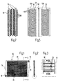
- the heat exchanger shown in FIG. 1 forms one example Heating register for heating a passenger compartment one by one Internal combustion engine driven vehicle. He points in known manner on a frame 10, the side Frame legs 12 and 14 are box-shaped.
- the Frame leg 12 contains one via an inlet connection 16 connectable with the cooling water return flow of the internal combustion engine Water inlet chamber, while the frame leg 14 a Contains water drainage chamber that has an outlet nozzle 18 connectable to a water pump of the internal combustion engine is.
- Both frame legs 12, 14 have an upper and one lower, preferably U-shaped frame legs in cross section 20 and 22 connected to each other in a corner stiff manner.
- a heating network is provided within the frame 10, which consists of a variety of individual, for example horizontal extending and superimposed liquid or Water pipes 24 is formed. These are at the end, as in known with the two chambers of the frame legs 12, 14th in connection, the sealed arrangement of Water pipes 24 of the heating network on the frame legs 12, 14 using cast resin or other suitable means can be accomplished.
- the frame legs 12, 14 and the in the frame 10 integrated liquid or water pipes 24 form a media guide body.
- the water pipes 24 preferably have the according to FIGS. 6a and 6b Cross section of a flat tube and are in the frame 10, in a common level, one above the other, provided that their flat tube wall parts 26 and 28 lie one above the other.
- both pipe wall parts 26 and 28 are in on the outside Pipe longitudinal direction at a distance from each other transversely to Pipe-axis-extending, shaft-like channels, lamellar webs 30 are provided so that the Media flowing through the heat exchanger are crossed.
- the water pipes 24 consist of pressure and hydrolysis-resistant, temperature-compatible, high-strength Plastic, such as PA 6.6, PEI, PEEK, PAI or PPS, these in two steps from a plastic film 32 by preferably 0.30 mm.
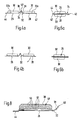
- This plastic film 32 is, for example, in one Thermoforming tool using a vacuum reshaped and into the shape shown in FIGS. 4a and 4b brought.
- the plastic film 32 thereby has two film halves 32a and 32b, which extend in the longitudinal direction of the film extending, inverted groove-like depression 34 with each other are flexibly connected.
- the side walls 36, 38 of this recess 34 expand it continuously to the outside and point to this in cross section Pitch circle shape.
- the bottom 40 of this recess 34 has Cross-section preferably in the form of a semicircle.
- the cross-sectional shape of the groove-like recess 34 provides sure that the plastic film 32 will fold in a way leaves that both film halves 32a and 32b congruent come to lie on top of each other (see FIGS. 6a and 6b) and themselves then the tube wall parts 26, 28 to the longitudinal side, through the Channel bottom 40 formed connecting edge extend parallel and thus the pipe cross-section over the entire pipe width is equal to.
- Both film halves 32a and 32b each have an outer Longitudinal edge piece 42 or 44, which to the adjoining Pipe wall part 26 or 28 are stepped in such a way that with the congruent assignment of both film halves 32a and 32b the tube wall parts run parallel to one another.
- the plastic film 32 has its longitudinal edge pieces 42 and 44 just tightly connect what for example by gluing or folding, but preferably by welding.
- the lamellar webs 30 have due to the deep-drawing or possibly a U-shaped embossing process Cross section with two web wall parts. These are after the Thermal treatment of the plastic film 32 connected together and thereby so stiffened that one in the water pipes 24 possibly high operating pressure of the heat exchanger it is ensured that the webs 30 expand Side and thus a reduction in the cross section of the shaft-like air channels 46 defined by the webs 30 and a consequent reduction in the hot air throughput cannot result.
- the lamellar webs 30 can be perpendicular to Extend pipe longitudinal axis. However, the in 5 shown slightly curved web formation, whereby in the folded state of the plastic film 32 the Ridges 30 support each other, as shown in FIG. 7 is indicated.
- the height of the webs 30 can thereby be smaller by half be selected as if they were linear and are supported directly on the adjacent water pipe 24 would. In the latter case, the webs 30 would have to both Film halves 32a and 32b also offset from one another to a gap are formed, the engagement of the webs 30 of the one film half between those of the other Half of the film again a reduction in the cross section of the Warm air ducts would result.
- the plastic film 32 has another reinforcement insert that increases their strength Form of a grid 48, which is made of glass or carbon fibers with a length of preferably 30 mm.
- fibers made of highly tear-resistant material are like aramid.
- the grid 48 is in this case in the plastic film 32 oriented that to form the webs 30, the network breakthroughs 50 Take a diamond shape in the vertical direction of the bridge. The oblique course the mesh threads 52 at an angle of 45 ° the grid 48 during the thermal transformation of the Plastic film 32 great elasticity or stretch.
- the plastic film can be short or long fibers are reinforced, advantageously short fibers with a relatively large web height and long fibers, for example can be used with a relatively short web height.
- the frame legs 20, 22 come in the explained In this respect, the formation of the water pipes 24 according to the invention essential importance than by this at accordingly operating pressures occurring, inflation of the water pipes 24 is prevented in the vertical direction of their webs 30.
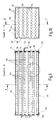
- the heat exchanger shown in FIGS. 9-15 has for example five horizontal levels of indoor air flowed through, preferably approximately in cross section cylindrical room air channels 110, which are at a radial distance run parallel to each other and from level to level are preferably offset.
- Cross to the Room air channels 110 and extend parallel to their levels are rectangular in cross-section in a total of six levels or shaft-like cooling air channels 112.
- Both types of channels 110 and 112 are one above the other stacked, preferably rectangular plates 114 one a plate pack forming a media guide body, which in turn each consist of two identical shapes and plate parts 16 and 18 symmetrically assigned to one another are made (see Figs. 11 and 12).
- these plate parts 116, 118 in one piece from a film of thermoplastic material, preferably polypropylene. You may as well in one piece from a foil made of heat-conducting metal, preferably aluminum.
- Each plate member 118 is along its two opposite longitudinal edge pieces 120 and 122 with such 120 'and 122' designated the one symmetrically assigned to them Plate part 116 preferably by gluing, welding, Pressure joining or folding tightly connected.
- Each plate part 116 or 118 is also provided with cooling room air molded, parallel, channel-like, in Cross-section semi-circular recesses 124 equipped. These can become cylindrical tubes or flat tubes complete, although in the latter case it is favorable, the two flat tube wall parts corrugated in cross section train.
- To form the cooling air channels 112 are to the Plate parts 116, 118 extend transversely to their depressions 124 and the airtight longitudinal edge parts 120, 122 extending, vertically protruding and parallel to each other Molded webs 126.
- the heat exchanger is used to control the temperature of the room air the web wall parts of the double-walled webs 126 preferably connect each other tightly to ensure that these do not become Can inflate side.
- Each plate 114 is thus characterized by upper and lower, in webs 126 lying in a common vertical plane. Recesses 124 and webs 126 give the thin Plastic films of preferably only 0.20 mm to 0.40 mm Thick existing plate parts 116, 118 a stiffness that ensures that in the mutual, firm bond of stacked plates 114 according to FIG stiffened media guide body is achieved.
- the webs 126 of a plate 114 for forming the cooling air channels 112 engage between these webs 126 of a plate 114 located below or above them, preferably in such a way that adjacent webs 126 touch one another (1st variant ) .
- the webs 126 of two plates 114 as indicated by dash-dotted lines, to engage in the middle between those of the other plate 116, as a result of which the number of cooling air ducts 112 can be doubled and the efficiency of the heat exchanger increases (second variant) .
- the plates 114 of the plate package or media guide body are together in one at their ends preferably made of plastic holding frame 128 or 130 kept sealed, which by means of an adhesive 132, preferably made of cast resin.
- the webs 126 of the upper and lower plates 114 are for Formation of the outside of the heat exchanger Cooling air channels 112 each through a board 132 or 134 covered, which is also on the end in the holding frame 128, 130 are set.
- the heat exchanger thus formed does not itself have any Formation of the channels 110 necessary for the condensate drain Housing on. It is a structural unit in a housing opening of an air conditioning unit can be inserted, to which Handling a handle 138 on its front face is provided. It can just as well be stuck in such a device be installed.
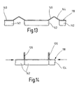
- FIGS. 13 and 14 An inventive method for manufacturing the plate parts 18 made of metal foil is shown in FIGS. 13 and 14 illustrated.
- vacuum thermoforming can be used become.
- the foil is preheated and in a tool, preferably in a single stroke, in the desired shape drawn. The aforementioned process step of Pushing them together is then not necessary.
- Tools are fins or sword-like metal strips used, the webs 126 shown in the figures molding.
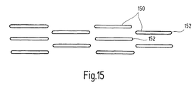
- the fin or sword-like metal strips do not cut through the plastic film, it will quasi deep-drawn. In this way, one in Circumferential direction closed circumferential contour of the web sections 150 and a rounded leading edge 152 is reached.
Landscapes
- Engineering & Computer Science (AREA)
- Physics & Mathematics (AREA)
- Thermal Sciences (AREA)
- Mechanical Engineering (AREA)
- General Engineering & Computer Science (AREA)
- Heat-Exchange Devices With Radiators And Conduit Assemblies (AREA)
Abstract
Description
- Figur 1
- eine Vorderansicht eines ursprünglich einen Kühler für das Kühlwasser einer Verbrennungskraftmaschine bildenden, erfindungsgemäß als Heizregister zur Erwärmung einer Fahrgastzelle verwendbaren Wärmetauschers;
- Figur 2
- einen Querschnitt des Wärmetauschers, entlang der Linie II-II der Fig. 1 gesehen.
- Figur 3
- einen in Fig. 2 durch einen strichpunktierten Kreis angedeuteten Ausschnitt, in vergrößertem Maßstab;
- Figuren 4a und 4b
- jeweils einen Querschnitt durch eine Kunststofffolie zur Bildung eines mit lamellenartigen Stegen bestückten Flüssigkeitsrohres;
- Figur 5
- eine Draufsicht auf die Kunststofffolie, in verkürzter Darstellung;
- Figuren 6a und 6b
- jeweils einen Querschnitt durch ein aus einer Folie gemäß Fig. 4a bzw. 4b gebildetes Flüssigkeitsrohr;
- Figur 7
- einen Schnitt entlang der Linie VII-VII der Fig. 3; und
- Figur 8
- die linke Hälfte der Fig. 4a in stark vergrößerter und teilweise aufgebrochen gezeigter Darstellung.
- Figur 9
- einen Längsschnitt eines zur Klimatisierung eines Raumes durch Regelung der Raumluftfeuchtigkeit vorgesehenen Wärmetauschers entlang der Linie B-B der Figur 10;
- Figur 10
- einen Querschnitt des Wärmetauschers entlang der Linie A-A der Figur 9;
- Figur 11
- einen durch einen strichpunktierten Kreis angedeuteten Ausschnitt der Darstellung gemäß Figur 9, in stark vergrößertem und verkürztem Maßstab;
- Figur 12
- eine schaubildliche Darstellung eines einen Medienführungskörper bildenden Plattenpakets des Wärmetauschers gemäß Figur 9 und 10;
- Figur 13
- einen Teillängsschnitt durch ein als Zuschnitt vorgeformtes Plattenteil aus Aluminiumfolie;
- Figur 14
- eine Darstellung des Plattenteils gemäß Figur 13, in zusammengeschobenem Zustand;
- Figur 15
- eine schematische Schnittansicht der zueinander versetzten Anordnung von Stegteilstücken.
Claims (3)
- Verwendung eines Wärmetauschers mit einem Medienführungskörper, der zwei Gruppen von sich kreuzenden Kanälen (24, 46) bzw. (110, 112) für getrennt zu führende Medien aufweist, von denen die eine Kanalgruppe (24; 110) rohrartig und die andere Kanalgruppe (46; 112) schachtartig ausgebildet ist und die letztere Kanalgruppe (46; 112) durch an die rohrartigen Kanäle (24; 110) außenseitig im Abstand voneinander vorgesehene und quer zur Rohrachse gerichtete Stege (30; 126) gebildet sind, wobei die rohrartigen Kanäle (24; 110) und die Stege (30; 126) aus wenigstens einer umgeformten, aus thermoplastischem Kunststoff (32) oder aus einem wärmeleitenden Metall bestehenden Folie (140) gemeinsam hergestellt sind, zur Temperaturregelung bzw. Klimaführung in Räumen.
- Verwendung eines Wärmetauscher nach Anspruch 1, dadurch gekennzeichnet, dass in der einen Gruppe von Kanälen (24, 46) Raumluft und in der anderen Gruppe von Kanälen (110, 112) Kühlluft geführt wird.
- Verwendung eines Wärmetauschers nach Anspruch 1, dadurch gekennzeichnet, dass in der einen Gruppe von Kanälen (46; 112) des Medienführungskörpers ein gasförmiges und in der anderen Gruppe von Kanälen (24; 110) ein flüssiges Medium zur Kühlung oder Erwärmung von Räumen geführt wird.
Applications Claiming Priority (4)
| Application Number | Priority Date | Filing Date | Title |
|---|---|---|---|
| DE10034568 | 2000-07-14 | ||
| DE2000134568 DE10034568A1 (de) | 2000-07-14 | 2000-07-14 | Kreuzstrom-Wärmetauscher |
| DE10057240A DE10057240C1 (de) | 1999-08-20 | 2000-11-18 | Verwendung eines Flüssigkeitskühlers für Verbrennungsmotoren |
| DE10057240 | 2000-11-18 |
Publications (2)
| Publication Number | Publication Date |
|---|---|
| EP1172626A2 true EP1172626A2 (de) | 2002-01-16 |
| EP1172626A3 EP1172626A3 (de) | 2003-11-26 |
Family
ID=26006400
Family Applications (1)
| Application Number | Title | Priority Date | Filing Date |
|---|---|---|---|
| EP01113370A Ceased EP1172626A3 (de) | 2000-07-14 | 2001-06-01 | Verwendung eines Wärmetauschers |
Country Status (2)
| Country | Link |
|---|---|
| US (1) | US20020005279A1 (de) |
| EP (1) | EP1172626A3 (de) |
Cited By (2)
| Publication number | Priority date | Publication date | Assignee | Title |
|---|---|---|---|---|
| DE202004007070U1 (de) * | 2004-05-03 | 2005-09-15 | Akg Thermotechnik Gmbh & Co Kg | Wärmeaustauscher, insbesondere für Kondensations-Wäschetrockner |
| EP2423633A4 (de) * | 2009-04-20 | 2014-04-30 | Kyungdong Navien Co Ltd | Wärmetauscher |
Families Citing this family (9)
| Publication number | Priority date | Publication date | Assignee | Title |
|---|---|---|---|---|
| NL1020483C1 (nl) * | 2002-04-26 | 2003-10-28 | Oxycell Holding Bv | Warmtewisselaar en werkwijze voor het vervaardigen daarvan. |
| JP2004092942A (ja) * | 2002-08-29 | 2004-03-25 | Denso Corp | 熱交換器 |
| JP2004125270A (ja) * | 2002-10-02 | 2004-04-22 | Denso Corp | 熱交換器およびその製造方法 |
| US20060000590A1 (en) * | 2004-06-09 | 2006-01-05 | Integral Technologies, Inc. | Low cost vehicle heat exchange devices manufactured from conductive loaded resin-based materials |
| US20050274013A1 (en) * | 2004-06-09 | 2005-12-15 | Integral Technologies, Inc. | Low cost vehicle heat exchange devices manufactured from conductive loaded resin-based materials |
| US20060021745A1 (en) * | 2004-07-28 | 2006-02-02 | Karl Fritze | Heat exchanger and fluid reservoir |
| DE102009013943A1 (de) * | 2009-03-19 | 2010-09-23 | Frank Will | Ölschmiersystem |
| JP5727327B2 (ja) * | 2011-08-08 | 2015-06-03 | 株式会社神戸製鋼所 | 熱交換器 |
| FR3050519B1 (fr) * | 2016-04-25 | 2019-09-06 | Novares France | Echangeur thermique en matiere plastique et vehicule comprenant cet echangeur thermique |
Citations (2)
| Publication number | Priority date | Publication date | Assignee | Title |
|---|---|---|---|---|
| DE19838525A1 (de) | 1997-09-03 | 1999-03-04 | Joma Polytec Kunststofftechnik | Kreuzstrom-Wärmetauscher für Kondensationswäschetrockner |
| DE19939531C1 (de) | 1999-08-20 | 2001-02-01 | Joma Polytec Kunststofftechnik | Flüssigkeitskühler für Verbrennungsmotoren sowie Verfahren zur Herstellung von Rohren für solche Flüssigkeitskühler |
Family Cites Families (3)
| Publication number | Priority date | Publication date | Assignee | Title |
|---|---|---|---|---|
| GB8824052D0 (en) * | 1988-10-13 | 1988-11-23 | Advanced Design & Mfg Ltd | Improvements in & relating to heat exchangers |
| US5335414A (en) * | 1993-03-29 | 1994-08-09 | Exaire Co. | Heat transfer cell and manufacturing apparatus |
| US5582241A (en) * | 1994-02-14 | 1996-12-10 | Yoho; Robert W. | Heat exchanging fins with fluid circulation lines therewithin |
-
2001
- 2001-06-01 EP EP01113370A patent/EP1172626A3/de not_active Ceased
- 2001-07-05 US US09/897,939 patent/US20020005279A1/en not_active Abandoned
Patent Citations (2)
| Publication number | Priority date | Publication date | Assignee | Title |
|---|---|---|---|---|
| DE19838525A1 (de) | 1997-09-03 | 1999-03-04 | Joma Polytec Kunststofftechnik | Kreuzstrom-Wärmetauscher für Kondensationswäschetrockner |
| DE19939531C1 (de) | 1999-08-20 | 2001-02-01 | Joma Polytec Kunststofftechnik | Flüssigkeitskühler für Verbrennungsmotoren sowie Verfahren zur Herstellung von Rohren für solche Flüssigkeitskühler |
Cited By (3)
| Publication number | Priority date | Publication date | Assignee | Title |
|---|---|---|---|---|
| DE202004007070U1 (de) * | 2004-05-03 | 2005-09-15 | Akg Thermotechnik Gmbh & Co Kg | Wärmeaustauscher, insbesondere für Kondensations-Wäschetrockner |
| EP2423633A4 (de) * | 2009-04-20 | 2014-04-30 | Kyungdong Navien Co Ltd | Wärmetauscher |
| US9250021B2 (en) | 2009-04-20 | 2016-02-02 | Kyungdong Navien Co., Ltd. | Heat exchanger |
Also Published As
| Publication number | Publication date |
|---|---|
| US20020005279A1 (en) | 2002-01-17 |
| EP1172626A3 (de) | 2003-11-26 |
Similar Documents
| Publication | Publication Date | Title |
|---|---|---|
| EP1992898B1 (de) | Wärmetauscher für gasförmige Medien | |
| DE2801076C3 (de) | Wärmeaustauscher bestehend aus Schichten von paarweise einander zugeordneten Wänden | |
| DE69911131T2 (de) | Wärmetauscher | |
| DE102004003790A1 (de) | Wärmetauscher, insbesondere Öl-/Kühlmittel-Kühler | |
| DE19815584A1 (de) | Zusammengesetzter Tankkörper eines Aufnahmetanks | |
| DE102009015849A1 (de) | Wärmetauscher | |
| DE10220532A1 (de) | Wärmetauscher | |
| EP1172626A2 (de) | Verwendung eines Wärmetauschers | |
| EP0982427B1 (de) | Kreuzstrom-Wärmetauscher für Kondensationswäschetrockner | |
| DE102012110003A1 (de) | Rohrwärmetauscher nach dem Gegenstromprinzip mit parallelen Strömungskanälen mit vergrösserter wärmeübertragender Oberfläche | |
| DE10345695A1 (de) | Wärmeaustauscher aus (Kunst)harz und Verfahren zu seiner Herstellung | |
| DE19963795A1 (de) | Heiz-, Belüftungs- und/oder Klimaanlage, umfassend einen mit einem Verdampfer ausgestatteten thermischen Kreis | |
| DE102009034303A1 (de) | Wärmeübertrager | |
| EP2310756B1 (de) | Einbauelement zum einbau in einer vorrichtung zur befeuchtung, reinigung und/oder kuehlung eines fluids, insbesondere gases wie z.b. luft, und verfahren zur herstellung eines einbaukörpers mit einem solchen einbauelement | |
| EP1203923B1 (de) | Wärmeaustauscher, insbesondere für Kondensations-Wäschetrockner | |
| EP0907061B1 (de) | Wärmeübertrager für eine Heiz- oder Klimaanlage eines Kraftfahrzeuges | |
| DE19838525C2 (de) | Kreuzstrom-Wärmetauscher für Kondensationswäschetrockner und Herstellungsverfahren | |
| DE10057240C1 (de) | Verwendung eines Flüssigkeitskühlers für Verbrennungsmotoren | |
| DE10112697A1 (de) | Wärmeübertrager, insbesondere für Kraftfahrzeuge | |
| EP1662223B1 (de) | Wärmeübertrager und Herstellungsverfahren | |
| DE10241635A1 (de) | Flachrohr-Wärmeübertrager sowie Herstellungsverfahren hierfür | |
| DE102008020230A1 (de) | Wärmetauscher sowie Wärmetauscherrohr | |
| EP1106729B1 (de) | Kreuzstrom-Wärmetauscher für Kondensationswäschetrockner | |
| DE19505641A1 (de) | Wärmetauscher | |
| DE102023123709B4 (de) | Thermomanagement Modul |
Legal Events
| Date | Code | Title | Description |
|---|---|---|---|
| PUAI | Public reference made under article 153(3) epc to a published international application that has entered the european phase |
Free format text: ORIGINAL CODE: 0009012 |
|
| AK | Designated contracting states |
Kind code of ref document: A2 Designated state(s): AT BE CH CY DE DK ES FI FR GB GR IE IT LI LU MC NL PT SE TR |
|
| AX | Request for extension of the european patent |
Free format text: AL;LT;LV;MK;RO;SI |
|
| PUAL | Search report despatched |
Free format text: ORIGINAL CODE: 0009013 |
|
| AK | Designated contracting states |
Kind code of ref document: A3 Designated state(s): AT BE CH CY DE DK ES FI FR GB GR IE IT LI LU MC NL PT SE TR |
|
| AX | Request for extension of the european patent |
Extension state: AL LT LV MK RO SI |
|
| 17P | Request for examination filed |
Effective date: 20040525 |
|
| AKX | Designation fees paid |
Designated state(s): DE IT |
|
| 17Q | First examination report despatched |
Effective date: 20040723 |
|
| STAA | Information on the status of an ep patent application or granted ep patent |
Free format text: STATUS: THE APPLICATION HAS BEEN REFUSED |
|
| 18R | Application refused |
Effective date: 20050523 |