EP1173040A2 - Lautsprecher und vorgespannte Gehäuse - Google Patents
Lautsprecher und vorgespannte Gehäuse Download PDFInfo
- Publication number
- EP1173040A2 EP1173040A2 EP01111253A EP01111253A EP1173040A2 EP 1173040 A2 EP1173040 A2 EP 1173040A2 EP 01111253 A EP01111253 A EP 01111253A EP 01111253 A EP01111253 A EP 01111253A EP 1173040 A2 EP1173040 A2 EP 1173040A2
- Authority
- EP
- European Patent Office
- Prior art keywords
- loudspeaker
- cabinet
- hollow conical
- rear plates
- fitted
- Prior art date
- Legal status (The legal status is an assumption and is not a legal conclusion. Google has not performed a legal analysis and makes no representation as to the accuracy of the status listed.)
- Withdrawn
Links
Images
Classifications
-
- H—ELECTRICITY
- H04—ELECTRIC COMMUNICATION TECHNIQUE
- H04R—LOUDSPEAKERS, MICROPHONES, GRAMOPHONE PICK-UPS OR LIKE ACOUSTIC ELECTROMECHANICAL TRANSDUCERS; ELECTRIC HEARING AIDS; PUBLIC ADDRESS SYSTEMS
- H04R1/00—Details of transducers, loudspeakers or microphones
- H04R1/20—Arrangements for obtaining desired frequency or directional characteristics
- H04R1/22—Arrangements for obtaining desired frequency or directional characteristics for obtaining desired frequency characteristic only
- H04R1/28—Transducer mountings or enclosures modified by provision of mechanical or acoustic impedances, e.g. resonator, damping means
- H04R1/2869—Reduction of undesired resonances, i.e. standing waves within enclosure, or of undesired vibrations, i.e. of the enclosure itself
- H04R1/2884—Reduction of undesired resonances, i.e. standing waves within enclosure, or of undesired vibrations, i.e. of the enclosure itself by means of the enclosure structure, i.e. strengthening or shape of the enclosure
- H04R1/2888—Reduction of undesired resonances, i.e. standing waves within enclosure, or of undesired vibrations, i.e. of the enclosure itself by means of the enclosure structure, i.e. strengthening or shape of the enclosure for loudspeaker transducers
Definitions
- the present invention relates to a loudspeaker, and more particularly a loudspeaker cabinet.
- the loudspeaker cabinet is made of thick plates in the hope of suppressing undesired resonance in its closed space, but such loudspeaker cabinet is not satisfactory.
- the loudspeaker cabinet of ceramic is found satisfactory to some extent, but the shaping of the cabinet is difficult because of its hardness, and its heaviness is a problem, also. Still disadvantageously, it produces accompanying sound inherent to the material.
- the inventor realized that undesired vibration is caused by deformation or distortion in the cabinet and that the cabinet if pre-deformed or pre-stressed is capable of preventing appearance of significant resonance in its closed space.
- the inventor has proposed that a speaker cabinet of duralumin is pre-stressed by using screw rods (see Japanese Patent 2000-224682(A)).
- the metal cannot be welded, and lacks ductility to be easily broken by bending. Such difficulty in workability makes it difficult to provide a cabinet structure that can be pre-stressed still more.
- One object of the present invention is to provide a loudspeaker cabinet structure which can be so pre-stressed as to suppress undesired resonance effectively.
- a loudspeaker comprising a cabinet and a loudspeaker unit fixed to the inside of said cabinet
- said cabinet comprises a hollow conical assembly comprising two conical bodies of high-rigidity metal, one press-fitted into the other; said hollow conical assembly having front and rear plates closing its front and rear openings.
- the press-fitting of one into the other conical body of high-rigidity by applying an increased pressure causes an extraordinary stress to appear in the hollow conical assembly far beyond the stress caused by pulling force.
- the conical body needs to be made of a sheet of metal of high-rigidity such as steel or duralumin of sufficient thickness.
- the front and rear plates may be press-fitted in the front and rear openings of the hollow conical assembly, and these plates are circular disks whose circumferences converge inward, the larger diameters of the circular disks being somewhat larger than the diameters of the front and rear openings of the hollow conical assembly.
- the loudspeaker unit may be fixed to the front plate by tightening screw rods, thereby applying an increased compression stress to the loudspeaker unit.
- the front and rear plates may be pulled toward each other by tightening screw rods, thereby fixing the front and rear plates to the hollow conical assembly.
- the front and rear plates may be annular plates each having an inward converging aperture made at its center, and a disk fitted in the inward converging aperture; and the disks fitted in the front and rear plates may be pulled toward each other by tightening screw rods, thereby fixing the front and rear plates to the hollow conical assembly.
- This arrangement will allow application of increased compression stress to the front and rear plates.
- a press machine In assembling a press machine is used in applying an extraordinary pressing force to one conical body to push it into the other conical body, thus providing a hollow conical assembly; and the front plate having the loudspeaker unit fixed thereto is press-fitted into the front opening of the hollow conical assembly with the aid of the press machine; and then the rear plate is press-fitted into the rear opening of the hollow conical assembly with the aid of the press machine, also.
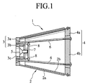
- a loudspeaker 1 according to the first embodiment comprises a cabinet 2 and a loudspeaker unit 5 fixed to the inside of the cabinet 2.
- the cabinet 2 comprises a hollow conical assembly comprising two conical bodies 2a and 2b of high-rigidity metal telescoped with front and rear plates 3 and 4 closing its front and rear openings.
- each conical body 2a and 2b are of almost same shape and size, one press-fitted into the other.
- Each conical body is made of a sheet of metal of high-rigidity, and the sheet of metal is thick enough to provide good resistance to an increased strength of compression and effective suppression of undesired vibration.
- the tapering angle is so selected that an increased compression stress may appear.
- such hollow conical assembly is made of three-millimeter thick sheet of metal of high-rigidity , and it has a tapering angle of approximately two degrees.
- a circular front plate 3 is welded to the front side of the hollow conical assembly 2 to close the front opening whereas a circular rear plate 4 is fixed to the rear side with screws to close the rear opening.
- Each plate is twenty millimeters thick.
- the front plate 3 comprises an outer annular plate 3a and an inner annular plate 3b, which is press-fitted in the outer annular plate 3a.
- the rear plate 4 comprises an annular plate 4a and a circular disk 4b, which is press-fitted in the annular plate 4a.
- Each annular plate 3a or 4a has an inward converging surface formed on its inner circular circumference
- each of the disk 3b and the inner annular plate 4b has an inward converging surface formed on its outer circumference.
- each screw rod is threadedly engaged in the tapped hole made in the inner annular plate 3b of the front plate 3 whereas the other threaded end appears outward on the circular disk 4b of the rear plate 4 to be threadedly engaged with a nut.
- a circular opening 3c is formed at the center of the inner annular plate 3b of the front plate 3 and the speaker unit 5 is fixed to the inner annular plate 3b at the periphery with screws.
- a backup plate 7 is applied to the rear side of the speaker unit 5 to push it to the front plate 3 by tightening four screws 8, which pass through the four corners of the backup plate 7 to be threadedly engaged with the tapped holes made in the inner annular plate 3b.
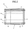
- a loudspeaker cabinet 10 using front and rear plates 11 and 12, each being a whole piece having no separate part.
- the front plate 11 is twenty millimeters thick, closing the front opening of the composite hollow conical body 2. It has two circular holes 11a and 11b made therein, and two loudspeaker units (not shown) are fixed to the circumferences of the circular holes 11 a and 11b with screws.
- the rear plate 12 is a twenty-millimeter thick circular plate closing the rear opening of the composite hollow conical body 2.
- the circumference of the real plate 12 converges inward at the same angle as the conical body 2b, and the larger diameter of the real plate 12 is somewhat larger than the diameter of the conical body 2b.
- the front opening end of the conical body 2a is chamfered on its inner circumference to diverge somewhat outward.
- the larger diameter of the front plate 11 is larger than the diameter of the front opening of the conical body 2a.
- Each plate 11 or 12 is press-fitted in the front or rear opening of the hollow conical assembly 2, and is fixed thereto with screws, thereby assuring that the hollow conical assembly 2 remain pre-stressed as it is.
- the front and rear plates 11 and 12 are pulled toward each other by tightening two screw rods 13 so that the hollow conical assembly may be subjected to an increased compression stress.
- One end of each screw rod 13 is threadedly engaged with the tapped hole made in the front plate, and the other end of the screw rod 13 appearing on the rear plate 12 is engaged with the nut.
- the loudspeaker cabinet is put in compressive-stressed condition, thus allowing the sound to travel at an increased speed in the cabinet and to rise quickly at the beginning of sound reproduction.
- Such a loudspeaker cabinet of excellent performance can be produced with ease and at low cost.
Landscapes
- Health & Medical Sciences (AREA)
- Otolaryngology (AREA)
- Physics & Mathematics (AREA)
- Engineering & Computer Science (AREA)
- Acoustics & Sound (AREA)
- Signal Processing (AREA)
- Details Of Audible-Bandwidth Transducers (AREA)
Applications Claiming Priority (2)
| Application Number | Priority Date | Filing Date | Title |
|---|---|---|---|
| JP2000212863A JP2002027581A (ja) | 2000-07-13 | 2000-07-13 | スピーカ |
| JP2000212863 | 2000-07-13 |
Publications (2)
| Publication Number | Publication Date |
|---|---|
| EP1173040A2 true EP1173040A2 (de) | 2002-01-16 |
| EP1173040A3 EP1173040A3 (de) | 2006-10-18 |
Family
ID=18708711
Family Applications (1)
| Application Number | Title | Priority Date | Filing Date |
|---|---|---|---|
| EP01111253A Withdrawn EP1173040A3 (de) | 2000-07-13 | 2001-05-15 | Lautsprecher und vorgespannte Gehäuse |
Country Status (3)
| Country | Link |
|---|---|
| US (1) | US6628797B2 (de) |
| EP (1) | EP1173040A3 (de) |
| JP (1) | JP2002027581A (de) |
Cited By (2)
| Publication number | Priority date | Publication date | Assignee | Title |
|---|---|---|---|---|
| WO2017201845A1 (zh) * | 2016-05-24 | 2017-11-30 | 大连理工大学 | 一种新型超薄声波阻抗变换器 |
| US10645484B2 (en) | 2016-12-23 | 2020-05-05 | Tadeusz Kwolek | Loudspeaker cabinets, systems, and methods of construction |
Families Citing this family (6)
| Publication number | Priority date | Publication date | Assignee | Title |
|---|---|---|---|---|
| US7006648B2 (en) * | 2003-10-22 | 2006-02-28 | Chao-Lang Wang | Speaker cabinet with increased air circulation efficiency |
| US7270215B2 (en) * | 2005-04-15 | 2007-09-18 | Step Technologies Inc. | Loudspeaker enclosure with damping material laminated within internal shearing brace |
| TW201134233A (en) * | 2010-03-25 | 2011-10-01 | Zhao-Lang Wang | Audio radiation type reflective sound box structure |
| US8757317B1 (en) * | 2013-05-03 | 2014-06-24 | Longinesteno Technology Complex Corporation | Barrel-shaped multidirectional loudspeaker enclosure structure |
| JP6949037B2 (ja) * | 2016-02-08 | 2021-10-13 | ウエスト ファーマスーティカル サービシーズ インコーポレイテッド | 針シールドプラー |
| KR20190124270A (ko) | 2017-03-10 | 2019-11-04 | 에프. 호프만-라 로슈 아게 | 다중특이적 항체의 생산 방법 |
Family Cites Families (10)
| Publication number | Priority date | Publication date | Assignee | Title |
|---|---|---|---|---|
| US3104730A (en) * | 1963-09-24 | Speaker enclosure | ||
| US3945461A (en) * | 1974-10-16 | 1976-03-23 | Robinson Ralph J | Sound speaker system |
| DE2738295C2 (de) * | 1977-08-25 | 1980-08-07 | Braun Ag, 6000 Frankfurt | Lautsprechergehäuse |
| US4850452A (en) * | 1985-03-08 | 1989-07-25 | Wolcott Henry O | Loudspeaker structure |
| US5082084A (en) * | 1990-07-23 | 1992-01-21 | Ye Ming Tsao | Extensible sound case |
| US5525767A (en) * | 1994-04-22 | 1996-06-11 | Fields; Walter | High-performance sound imaging system |
| US5644109A (en) * | 1995-05-30 | 1997-07-01 | Newman; Ottis G. | Speaker enclosure |
| GB2324928B (en) * | 1997-05-02 | 2001-09-12 | B & W Loudspeakers | Loudspeaker systems |
| US6055320A (en) * | 1998-02-26 | 2000-04-25 | Soundtube Entertainment | Directional horn speaker system |
| JP4132349B2 (ja) | 1999-02-02 | 2008-08-13 | 有限会社ゾルゾ | スピーカ |
-
2000
- 2000-07-13 JP JP2000212863A patent/JP2002027581A/ja active Pending
-
2001
- 2001-04-17 US US09/835,488 patent/US6628797B2/en not_active Expired - Fee Related
- 2001-05-15 EP EP01111253A patent/EP1173040A3/de not_active Withdrawn
Cited By (3)
| Publication number | Priority date | Publication date | Assignee | Title |
|---|---|---|---|---|
| WO2017201845A1 (zh) * | 2016-05-24 | 2017-11-30 | 大连理工大学 | 一种新型超薄声波阻抗变换器 |
| US10356511B2 (en) | 2016-05-24 | 2019-07-16 | Dalian University Of Technology | Ultrathin acoustic impedance converter |
| US10645484B2 (en) | 2016-12-23 | 2020-05-05 | Tadeusz Kwolek | Loudspeaker cabinets, systems, and methods of construction |
Also Published As
| Publication number | Publication date |
|---|---|
| US20020006210A1 (en) | 2002-01-17 |
| JP2002027581A (ja) | 2002-01-25 |
| US6628797B2 (en) | 2003-09-30 |
| EP1173040A3 (de) | 2006-10-18 |
Similar Documents
| Publication | Publication Date | Title |
|---|---|---|
| DE102014115443B4 (de) | Niederquerschnitt-Lautsprecher-Wandler | |
| JP7216179B2 (ja) | クリップに基づく、取り付け面に対するスピーカーの保持 | |
| US20080118098A1 (en) | Ultra low frequency transducer and loud speaker comprising same | |
| US6628797B2 (en) | Loudspeaker-and-pre-stressed cabinet | |
| CN109788406A (zh) | 磁路系统和发声装置 | |
| US10659857B1 (en) | Rapidly mountable ceiling loudspeaker device | |
| EP3614698B1 (de) | Dämpfungseinrichtung für einen hörer eines hörinstruments sowie hörinstrument mit einer solchen dämpfungseinrichtung | |
| JP2015109534A (ja) | スピーカーグリルの射出成形体とその成形方法 | |
| EP2280556B1 (de) | Lautsprecherbox | |
| US20060120552A1 (en) | Loudspeaker | |
| JP3891354B2 (ja) | 音響放射装置用電磁変換装置及び音響放射装置 | |
| JP6586977B2 (ja) | 隔離された共鳴を提供するドラムラグホルダ及びドラム | |
| US20240007794A1 (en) | Distributed mode loudspeaker with free motion heat sink | |
| CN221151564U (zh) | 一种扬声器模组 | |
| JP3743842B2 (ja) | スピーカ | |
| JPH0634397U (ja) | スピーカ | |
| JP4132349B2 (ja) | スピーカ | |
| KR102205433B1 (ko) | 압전 소자를 구비한 스피커 | |
| KR0139866Y1 (ko) | 자동차용 스피커의 주스피커와 보조스피커 고정장치 | |
| CN209105439U (zh) | 一种新型扬声器双层弹波组件 | |
| JP3043698U (ja) | 一体複合成型のマイクロホン | |
| JPS6132880B2 (de) | ||
| JP5985006B1 (ja) | スピーカ | |
| JP4264027B2 (ja) | スピーカ | |
| DE10140386B4 (de) | Lautsprecher |
Legal Events
| Date | Code | Title | Description |
|---|---|---|---|
| PUAI | Public reference made under article 153(3) epc to a published international application that has entered the european phase |
Free format text: ORIGINAL CODE: 0009012 |
|
| AK | Designated contracting states |
Kind code of ref document: A2 Designated state(s): AT BE CH CY DE DK ES FI FR GB GR IE IT LI LU MC NL PT SE TR |
|
| AX | Request for extension of the european patent |
Free format text: AL;LT;LV;MK;RO;SI |
|
| PUAL | Search report despatched |
Free format text: ORIGINAL CODE: 0009013 |
|
| AK | Designated contracting states |
Kind code of ref document: A3 Designated state(s): AT BE CH CY DE DK ES FI FR GB GR IE IT LI LU MC NL PT SE TR |
|
| AX | Request for extension of the european patent |
Extension state: AL LT LV MK RO SI |
|
| AKX | Designation fees paid |
Designated state(s): DE DK FR GB IT NL |
|
| STAA | Information on the status of an ep patent application or granted ep patent |
Free format text: STATUS: THE APPLICATION IS DEEMED TO BE WITHDRAWN |
|
| 18D | Application deemed to be withdrawn |
Effective date: 20070419 |