EP1173249B1 - Interventionsvorrichtung - Google Patents
Interventionsvorrichtung Download PDFInfo
- Publication number
- EP1173249B1 EP1173249B1 EP00926957A EP00926957A EP1173249B1 EP 1173249 B1 EP1173249 B1 EP 1173249B1 EP 00926957 A EP00926957 A EP 00926957A EP 00926957 A EP00926957 A EP 00926957A EP 1173249 B1 EP1173249 B1 EP 1173249B1
- Authority
- EP
- European Patent Office
- Prior art keywords
- needle
- handle
- intervention device
- tissue
- intervention
- Prior art date
- Legal status (The legal status is an assumption and is not a legal conclusion. Google has not performed a legal analysis and makes no representation as to the accuracy of the status listed.)
- Expired - Lifetime
Links
Images

Classifications
-
- A—HUMAN NECESSITIES
- A61—MEDICAL OR VETERINARY SCIENCE; HYGIENE
- A61B—DIAGNOSIS; SURGERY; IDENTIFICATION
- A61B17/00—Surgical instruments, devices or methods
- A61B17/34—Trocars; Puncturing needles
- A61B17/3403—Needle locating or guiding means
-
- A—HUMAN NECESSITIES
- A61—MEDICAL OR VETERINARY SCIENCE; HYGIENE
- A61B—DIAGNOSIS; SURGERY; IDENTIFICATION
- A61B10/00—Instruments for taking body samples for diagnostic purposes; Other methods or instruments for diagnosis, e.g. for vaccination diagnosis, sex determination or ovulation-period determination; Throat striking implements
- A61B10/02—Instruments for taking cell samples or for biopsy
- A61B10/0233—Pointed or sharp biopsy instruments
-
- A—HUMAN NECESSITIES
- A61—MEDICAL OR VETERINARY SCIENCE; HYGIENE
- A61B—DIAGNOSIS; SURGERY; IDENTIFICATION
- A61B17/00—Surgical instruments, devices or methods
- A61B2017/0046—Surgical instruments, devices or methods with a releasable handle; with handle and operating part separable
-
- A—HUMAN NECESSITIES
- A61—MEDICAL OR VETERINARY SCIENCE; HYGIENE
- A61B—DIAGNOSIS; SURGERY; IDENTIFICATION
- A61B17/00—Surgical instruments, devices or methods
- A61B2017/0046—Surgical instruments, devices or methods with a releasable handle; with handle and operating part separable
- A61B2017/00469—Surgical instruments, devices or methods with a releasable handle; with handle and operating part separable for insertion of instruments, e.g. guide wire, optical fibre
-
- A—HUMAN NECESSITIES
- A61—MEDICAL OR VETERINARY SCIENCE; HYGIENE
- A61B—DIAGNOSIS; SURGERY; IDENTIFICATION
- A61B17/00—Surgical instruments, devices or methods
- A61B2017/00831—Material properties
- A61B2017/00902—Material properties transparent or translucent
- A61B2017/00911—Material properties transparent or translucent for fields applied by a magnetic resonance imaging system
-
- A—HUMAN NECESSITIES
- A61—MEDICAL OR VETERINARY SCIENCE; HYGIENE
- A61B—DIAGNOSIS; SURGERY; IDENTIFICATION
- A61B17/00—Surgical instruments, devices or methods
- A61B2017/00831—Material properties
- A61B2017/00902—Material properties transparent or translucent
- A61B2017/00924—Material properties transparent or translucent for ultrasonic waves
-
- A—HUMAN NECESSITIES
- A61—MEDICAL OR VETERINARY SCIENCE; HYGIENE
- A61B—DIAGNOSIS; SURGERY; IDENTIFICATION
- A61B17/00—Surgical instruments, devices or methods
- A61B17/34—Trocars; Puncturing needles
- A61B17/3403—Needle locating or guiding means
- A61B2017/3405—Needle locating or guiding means using mechanical guide means
Definitions
- the invention relates to an intervention device a needle and a first handle, the first Handle is firmly connected to the needle, as well as with a second handle.
- Intervention devices for human use or animal body known in different Type and used for different purposes.
- These intervention devices have one thing in common Needle for intervention in the particular human body is introduced.
- the intervention device has this needle first handle with which the person treating the Inserting the needle into the tissue controls. This is the first handle with the needle firmly in the sense connected that the connection between the needle and the Handle is sufficiently firm to achieve the desired one Control of the needle when entering the tissue enable. You can do this with the needle either permanently, i.e. not detachable, firmly connected but can also be frictional, for example to be releasably connected to the insertion.
- the known intervention devices will be like already mentioned, used for various purposes.
- these intervention devices in the As part of a pain and tumor therapy Infusion needles are used, initially up to therapeutic area are advanced, whereupon then a medically effective one Substance is injected.
- the well-known Intervention devices in certain configurations for obtaining tissue samples from human or animal body used for so-called biopsy.
- the needle is in turn as precisely as possible the tissue to be examined or treated inserted, whereupon a mechanism in the needle is triggered, the one from the surrounding tissue Tissue core takes.
- the present invention has for its object a To provide intervention device that optimal controllability when penetrating the tissue and at the same time optimal septic conditions guaranteed.
- the second handle when Insertion in the tissue in the longitudinal direction on the Needle is arranged.
- the Needle is passed through this second handle and because of the significantly enlarged Surface of the leading hand on the second handle and thus a much improved one on the needle Control the penetration of the needle into the tissue guaranteed and at the same time, since no direct contact between the gripping hand and the needle arises, optimal aseptic conditions are present.
- Intervention device designs exist in that these are often combined with a imaging diagnostics are used in Maps the penetration of the needle into the tissue in real time that precise control of the advancement of the needle to the diseased tissue is possible.
- a procedure for imaging diagnostics is regularly used here Computed tomography, which real-time images over the Vording the needle into the tissue supplies, inserted.
- the problem here is that the electromagnetic X-rays used in computed tomography Image acquisition is used, although on a tight limited area is focusable, this area itself due to the principle, however, at least partially with the The needle penetration point overlaps the tissue.
- the needle in the Proximity of the puncture point via two fingers of one hand treating person is at least the Fingertips of the treating person of an elevated Radiation exposure through electromagnetic Exposed to x-rays.
- the intensity is this x-ray radiation in computer tomography relatively low, however, results from the Frequency of those controlled by computer tomography Interventions in the long run an unjustifiable Radiation exposure of the fingers of the treating person.
- Intervention device according to a first particular advantageous embodiment further developed in that the first and / or second handle radially to the axis of the Have an extension.
- Intervention device within the framework of a imaging-controlled intervention is it further advantageous that the material of the first and / or second handle transparent for electromagnetic Radiation is so that it is guaranteed that the handle is invisible in the picture when controlling the intrusion, i.e. the view does not disturb.
- the second handle which can be moved on the needle, is in superfluous at the moment when the Intervention device in the desired tissue area was introduced and should not be moved any further.
- the puncture site may be due to its weight and weight uncomfortable for the patient for this very reason.
- the second handle of the Intervention device according to the invention preferably a Longitudinal slot for inserting the needle into the axial Guiding the second handle radially from one direction to the axis of the needle. This ensures that the second handle, for example, after Advance of the intervention device to the desired location is removable. This also has the Advantage that the second handle reused several times can be.
- tumor therapy is the Invention in the needle a removable inner cannula arranged when the needle penetrates the tissue prevents tissue fluid and - material penetrates.
- the third handle with the first Handle is detachably connected.
- the embodiment shown in Fig. 1 Intervention device has a Needle 1 and a first handle 2, the first Handle 2 with the needle 1 at least as firmly connected is that the transfer of one for incorporation into the Tissue necessary force from the first handle 2 the needle 1 is guaranteed.
- the invention 1 also shows an embodiment second handle 3, which handle 3 on the Needle 1 can be moved in the longitudinal direction of needle 1 is arranged or the needle 1 by the second handle 3 can be pushed through.
- the concrete Application is the second handle 3 in one Position in which she regularly ends with her the needle 1 facing end at least near the Tissue surface of the patient to be treated.
- the needle 1 is the first Handle 2 by the one attacking the needle 1 Control of the penetration of the needle 1 enable Handle 3 pushed into the tissue.
- both the first handle 2 and the second handle 3 Extensions 4, 5 that are attached to an attack on the Handle 2, 3 outside the radiation range of one imaging diagnostics.
- Extensions 4, 5 that are attached to an attack on the Handle 2, 3 outside the radiation range of one imaging diagnostics.
- extensions 4, 5 of handles 2, 3 ensure are in the illustrated Embodiment in the extensions 4, 5 openings 6 provided.
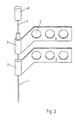
- Fig. 2 that is shown in Fig. 1 Embodiment in a perspective view the needle 1, the first handle 2, the second handle 3 and the two extensions 4, 5 shown.
- Fig. 2 is further shown that in the needle 1 a extractable inner cannula 7 for closing the needle 1 is provided when inserted into the tissue.
- the Inner cannula 7 is at its upper end with a third Handle 8 provided that easy pulling out of Inner cannula 7 guaranteed from the needle 1.
Landscapes
- Health & Medical Sciences (AREA)
- Surgery (AREA)
- Life Sciences & Earth Sciences (AREA)
- Animal Behavior & Ethology (AREA)
- Public Health (AREA)
- Engineering & Computer Science (AREA)
- Biomedical Technology (AREA)
- Heart & Thoracic Surgery (AREA)
- Medical Informatics (AREA)
- Molecular Biology (AREA)
- Pathology (AREA)
- General Health & Medical Sciences (AREA)
- Nuclear Medicine, Radiotherapy & Molecular Imaging (AREA)
- Veterinary Medicine (AREA)
- Surgical Instruments (AREA)
- Infusion, Injection, And Reservoir Apparatuses (AREA)
- Optical Communication System (AREA)
- Separation By Low-Temperature Treatments (AREA)
- Massaging Devices (AREA)
- Finger-Pressure Massage (AREA)
- Apparatus For Radiation Diagnosis (AREA)
Description
- Fig. 1
- ein Ausführungsbeispiel einer erfindungsgemäßen Interventionsvorrichtung in einer Seitenansicht und
- Fig. 2
- das Ausführungsbeispiel einer erfindungsgemäßen Interventionsvorrichtung in einer perspektivischen Ansicht.
Claims (6)
- Interventionsvorrichtung mit einer Nadel (1) und einer ersten Handhabe (2), wobei die erste Handhabe (2) mit der Nadel (1) fest verbunden ist, sowie mit einer zweiten Handhabe (3),
darduch gekennzeichnet, daß die zweite Handhabe (3) beim Einführen in das Gewebe in Längsrichtung verschiebbar auf der Nadel (1) angeordnet ist. - Interventionsvorrichtung nach Anspruch 1,
dadurch gekennzeichnet, daß die erste und/oder zweite Handhabe (2, 3) radial zur Achse der Nadel (1) eine Verlängerung (4, 5) aufweisen. - Interventionsvorrichtung nach Anspruch 1 oder 2,
dadurch gekennzeichnet, daß das Material der ersten und/oder zweiten Handhabe (2, 3) transparent für elektromagnetische Strahlung ist. - Interventionsvorrichtung nach einem der Ansprüche 1 bis 3,
dadurch gekennzeichnet, daß die zweite Handhabe (3) einen Längsschlitz zum Einbringen der Nadel (1) in die axiale Führung der zweiten Handhabe (3) aus einer Richtung radial zur Achse der Nadel (1) aufweist. - Interventionsvorrichtung nach einem der Ansprüche 1 bis 4,
dadurch gekennzeichnet, daß in der Nadel eine entfernbare Innenkanüle (7) angeordnet ist. - Interventionsvorrichtung nach Anspruch 5,
dadurch gekennzeichnet, daß die Innenkanüle (7) an einer dritten Handhabe (8) befestigt ist und die dritte Handhabe (8) mit der ersten Handhabe (2) lösbar verbindbar ist.
Applications Claiming Priority (3)
| Application Number | Priority Date | Filing Date | Title |
|---|---|---|---|
| DE19918483 | 1999-04-23 | ||
| DE19918483A DE19918483C1 (de) | 1999-04-23 | 1999-04-23 | Interventionsvorrichtung mit Handhabe für medizinische Zwecke |
| PCT/EP2000/003436 WO2000064526A1 (de) | 1999-04-23 | 2000-04-15 | Interventionsvorrichtung |
Publications (2)
| Publication Number | Publication Date |
|---|---|
| EP1173249A1 EP1173249A1 (de) | 2002-01-23 |
| EP1173249B1 true EP1173249B1 (de) | 2003-08-20 |
Family
ID=7905630
Family Applications (1)
| Application Number | Title | Priority Date | Filing Date |
|---|---|---|---|
| EP00926957A Expired - Lifetime EP1173249B1 (de) | 1999-04-23 | 2000-04-15 | Interventionsvorrichtung |
Country Status (7)
| Country | Link |
|---|---|
| EP (1) | EP1173249B1 (de) |
| JP (1) | JP2002541992A (de) |
| AT (1) | ATE247500T1 (de) |
| AU (1) | AU4550600A (de) |
| DE (2) | DE19918483C1 (de) |
| ES (1) | ES2207507T3 (de) |
| WO (1) | WO2000064526A1 (de) |
Families Citing this family (4)
| Publication number | Priority date | Publication date | Assignee | Title |
|---|---|---|---|---|
| DE10224336B4 (de) | 2002-06-01 | 2004-04-08 | University Of Dundee, Dundee | Medizinisches Instrument |
| WO2017037720A1 (en) * | 2015-09-06 | 2017-03-09 | Fna Technologies Ltd. | Needle—handling device |
| US11253236B2 (en) | 2019-10-21 | 2022-02-22 | Onepass Medical Ltd. | Needle-handling device |
| JP2023106785A (ja) * | 2022-01-21 | 2023-08-02 | 東日本電信電話株式会社 | 注射針 |
Family Cites Families (9)
| Publication number | Priority date | Publication date | Assignee | Title |
|---|---|---|---|---|
| US4013080A (en) * | 1974-10-03 | 1977-03-22 | Froning Edward C | Cannula connector and direction indicator means for injection system |
| DE8614252U1 (de) * | 1986-05-26 | 1987-09-24 | Saueressig, Ulrich, Dr.med., 5600 Wuppertal | Kanülenaufbau für Dialysen |
| DE3701585A1 (de) * | 1986-05-26 | 1987-12-03 | Saueressig Ulrich | Kanuele |
| DE8914941U1 (de) * | 1989-12-19 | 1990-09-27 | B. Braun Melsungen Ag, 34212 Melsungen | Punktionsbesteck |
| US5112312A (en) * | 1991-03-14 | 1992-05-12 | Luther Medical Products, Inc. | Vascular/venous access device and method of utilizing and forming the same |
| US5304144A (en) * | 1993-03-17 | 1994-04-19 | Becton, Dickinson And Company | Catheter introducer with enhanced needle gripping |
| US5429598A (en) * | 1994-04-19 | 1995-07-04 | Applied Medical Resources Corporation | Surgical access device and procedure |
| US5498241A (en) * | 1994-12-08 | 1996-03-12 | Abbott Laboratories | Winged needle assembly with protective member |
| US5944695A (en) * | 1997-09-30 | 1999-08-31 | Becton, Dickinson And Company | Multiple sheath catheter using multiple stages and method of use |
-
1999
- 1999-04-23 DE DE19918483A patent/DE19918483C1/de not_active Expired - Fee Related
-
2000
- 2000-04-15 JP JP2000613514A patent/JP2002541992A/ja active Pending
- 2000-04-15 AT AT00926957T patent/ATE247500T1/de not_active IP Right Cessation
- 2000-04-15 WO PCT/EP2000/003436 patent/WO2000064526A1/de not_active Ceased
- 2000-04-15 ES ES00926957T patent/ES2207507T3/es not_active Expired - Lifetime
- 2000-04-15 AU AU45506/00A patent/AU4550600A/en not_active Abandoned
- 2000-04-15 EP EP00926957A patent/EP1173249B1/de not_active Expired - Lifetime
- 2000-04-15 DE DE50003367T patent/DE50003367D1/de not_active Expired - Fee Related
Also Published As
| Publication number | Publication date |
|---|---|
| ATE247500T1 (de) | 2003-09-15 |
| DE50003367D1 (de) | 2003-09-25 |
| JP2002541992A (ja) | 2002-12-10 |
| WO2000064526A1 (de) | 2000-11-02 |
| AU4550600A (en) | 2000-11-10 |
| DE19918483C1 (de) | 2001-01-18 |
| ES2207507T3 (es) | 2004-06-01 |
| EP1173249A1 (de) | 2002-01-23 |
Similar Documents
| Publication | Publication Date | Title |
|---|---|---|
| DE60032052T2 (de) | Vorrichtung zum perkutanen Implantieren eines paddelartigen Leiters | |
| EP2589348B1 (de) | Vorrichtung zur Explantation von Elektrodenleitungen | |
| DE10042606A1 (de) | Medizinisches Gerät | |
| DE4419894A1 (de) | Endoskopische Punktionsnadelvorrichtung | |
| DE19510455A1 (de) | Chirurgisches Instrument zum stoßartigen Einführen einer intraossären Trokarnadel | |
| EP2827924A1 (de) | Sicherheitsnadelvorrichtung, insbesondere zur punktion von in einem menschlichen oder tierischen körper subkutan implantierten port | |
| DE69100973T2 (de) | Wegwerf-einmalverwendbare Infusionsvorrichtung mit Kappe für die Nadel nach Verwendung. | |
| DE3403962A1 (de) | Stichkanalvorbereitungsgeraet fuer die perkutane nephroskopie | |
| DE102013001105A1 (de) | Gefäßzugangsvorrichtung zur reproduzierbaren Einführung einer Kanule in eine Punktionsstelle | |
| DE102019129556A1 (de) | Lichtapplikator | |
| WO2007031264A1 (de) | Medizinisches instrument | |
| DE202013012340U1 (de) | Werkzeuge zur transkutanen Implantation und Systeme | |
| EP1077651B1 (de) | Punktionsvorrichtung für schichtaufnahmeverfahren | |
| DE4416656C2 (de) | Vorrichtung zur Schaffung eines Venenzuganges | |
| EP1924313B8 (de) | Medizinisches instrument | |
| DE19918483C1 (de) | Interventionsvorrichtung mit Handhabe für medizinische Zwecke | |
| DE60119528T2 (de) | Anordnung und Verfahren für das Zusammenwirken mit einem internen Körperorgan | |
| DE10297813B4 (de) | Vorrichtung, die den Schmerz des Einstichs einer Spritze in eine tolerierbare Sinnesempfindung umwandelt | |
| DE102008019304A1 (de) | Kathetereinrichtung für perkutane Eingriffe | |
| DE10100756A1 (de) | Vorrichtung zur Durchführung einer perkutanen Intervention in den Bereich einer menschlichen oder tierischen Lunge | |
| DE19707851C2 (de) | Nadelinstrument | |
| DE102022121987B3 (de) | Medizinisches Instrument | |
| DE19959975A1 (de) | Kanüle und Instrumentenset | |
| EP0343520A2 (de) | Ureter-Katheter-set | |
| DE10064458C1 (de) | Nadelhalter |
Legal Events
| Date | Code | Title | Description |
|---|---|---|---|
| PUAI | Public reference made under article 153(3) epc to a published international application that has entered the european phase |
Free format text: ORIGINAL CODE: 0009012 |
|
| 17P | Request for examination filed |
Effective date: 20011019 |
|
| AK | Designated contracting states |
Kind code of ref document: A1 Designated state(s): AT BE CH CY DE DK ES FI FR GB GR IE IT LI LU MC NL PT SE |
|
| AX | Request for extension of the european patent |
Free format text: AL;LT;LV;MK;RO;SI |
|
| 17Q | First examination report despatched |
Effective date: 20020719 |
|
| GRAH | Despatch of communication of intention to grant a patent |
Free format text: ORIGINAL CODE: EPIDOS IGRA |
|
| GRAH | Despatch of communication of intention to grant a patent |
Free format text: ORIGINAL CODE: EPIDOS IGRA |
|
| GRAA | (expected) grant |
Free format text: ORIGINAL CODE: 0009210 |
|
| AK | Designated contracting states |
Designated state(s): AT BE CH CY DE DK ES FI FR GB GR IE IT LI LU MC NL PT SE |
|
| PG25 | Lapsed in a contracting state [announced via postgrant information from national office to epo] |
Ref country code: IE Free format text: LAPSE BECAUSE OF FAILURE TO SUBMIT A TRANSLATION OF THE DESCRIPTION OR TO PAY THE FEE WITHIN THE PRESCRIBED TIME-LIMIT Effective date: 20030820 Ref country code: FI Free format text: LAPSE BECAUSE OF FAILURE TO SUBMIT A TRANSLATION OF THE DESCRIPTION OR TO PAY THE FEE WITHIN THE PRESCRIBED TIME-LIMIT Effective date: 20030820 Ref country code: CY Free format text: LAPSE BECAUSE OF FAILURE TO SUBMIT A TRANSLATION OF THE DESCRIPTION OR TO PAY THE FEE WITHIN THE PRESCRIBED TIME-LIMIT Effective date: 20030820 |
|
| REG | Reference to a national code |
Ref country code: GB Ref legal event code: FG4D Free format text: NOT ENGLISH |
|
| REG | Reference to a national code |
Ref country code: CH Ref legal event code: EP |
|
| REG | Reference to a national code |
Ref country code: IE Ref legal event code: FG4D Free format text: GERMAN |
|
| REF | Corresponds to: |
Ref document number: 50003367 Country of ref document: DE Date of ref document: 20030925 Kind code of ref document: P |
|
| PG25 | Lapsed in a contracting state [announced via postgrant information from national office to epo] |
Ref country code: SE Free format text: LAPSE BECAUSE OF FAILURE TO SUBMIT A TRANSLATION OF THE DESCRIPTION OR TO PAY THE FEE WITHIN THE PRESCRIBED TIME-LIMIT Effective date: 20031120 Ref country code: GR Free format text: LAPSE BECAUSE OF FAILURE TO SUBMIT A TRANSLATION OF THE DESCRIPTION OR TO PAY THE FEE WITHIN THE PRESCRIBED TIME-LIMIT Effective date: 20031120 Ref country code: DK Free format text: LAPSE BECAUSE OF FAILURE TO SUBMIT A TRANSLATION OF THE DESCRIPTION OR TO PAY THE FEE WITHIN THE PRESCRIBED TIME-LIMIT Effective date: 20031120 |
|
| GBT | Gb: translation of ep patent filed (gb section 77(6)(a)/1977) |
Effective date: 20031208 |
|
| PG25 | Lapsed in a contracting state [announced via postgrant information from national office to epo] |
Ref country code: PT Free format text: LAPSE BECAUSE OF FAILURE TO SUBMIT A TRANSLATION OF THE DESCRIPTION OR TO PAY THE FEE WITHIN THE PRESCRIBED TIME-LIMIT Effective date: 20040120 |
|
| LTIE | Lt: invalidation of european patent or patent extension |
Effective date: 20030820 |
|
| REG | Reference to a national code |
Ref country code: CH Ref legal event code: NV Representative=s name: SCHMAUDER & PARTNER AG PATENTANWALTSBUERO |
|
| REG | Reference to a national code |
Ref country code: IE Ref legal event code: FD4D |
|
| PG25 | Lapsed in a contracting state [announced via postgrant information from national office to epo] |
Ref country code: LU Free format text: LAPSE BECAUSE OF NON-PAYMENT OF DUE FEES Effective date: 20040415 |
|
| PGFP | Annual fee paid to national office [announced via postgrant information from national office to epo] |
Ref country code: NL Payment date: 20040422 Year of fee payment: 5 Ref country code: GB Payment date: 20040422 Year of fee payment: 5 Ref country code: FR Payment date: 20040422 Year of fee payment: 5 |
|
| PG25 | Lapsed in a contracting state [announced via postgrant information from national office to epo] |
Ref country code: MC Free format text: LAPSE BECAUSE OF NON-PAYMENT OF DUE FEES Effective date: 20040430 Ref country code: BE Free format text: LAPSE BECAUSE OF NON-PAYMENT OF DUE FEES Effective date: 20040430 |
|
| PGFP | Annual fee paid to national office [announced via postgrant information from national office to epo] |
Ref country code: ES Payment date: 20040506 Year of fee payment: 5 |
|
| REG | Reference to a national code |
Ref country code: ES Ref legal event code: FG2A Ref document number: 2207507 Country of ref document: ES Kind code of ref document: T3 |
|
| ET | Fr: translation filed | ||
| PLBE | No opposition filed within time limit |
Free format text: ORIGINAL CODE: 0009261 |
|
| STAA | Information on the status of an ep patent application or granted ep patent |
Free format text: STATUS: NO OPPOSITION FILED WITHIN TIME LIMIT |
|
| 26N | No opposition filed |
Effective date: 20040524 |
|
| BERE | Be: lapsed |
Owner name: *GRATZKI TORSTEN Effective date: 20040430 |
|
| PG25 | Lapsed in a contracting state [announced via postgrant information from national office to epo] |
Ref country code: IT Free format text: LAPSE BECAUSE OF NON-PAYMENT OF DUE FEES Effective date: 20050415 Ref country code: GB Free format text: LAPSE BECAUSE OF NON-PAYMENT OF DUE FEES Effective date: 20050415 |
|
| PG25 | Lapsed in a contracting state [announced via postgrant information from national office to epo] |
Ref country code: ES Free format text: LAPSE BECAUSE OF NON-PAYMENT OF DUE FEES Effective date: 20050416 |
|
| PGFP | Annual fee paid to national office [announced via postgrant information from national office to epo] |
Ref country code: DE Payment date: 20051025 Year of fee payment: 6 Ref country code: CH Payment date: 20051025 Year of fee payment: 6 |
|
| PGFP | Annual fee paid to national office [announced via postgrant information from national office to epo] |
Ref country code: AT Payment date: 20051031 Year of fee payment: 6 |
|
| PG25 | Lapsed in a contracting state [announced via postgrant information from national office to epo] |
Ref country code: NL Free format text: LAPSE BECAUSE OF NON-PAYMENT OF DUE FEES Effective date: 20051101 |
|
| GBPC | Gb: european patent ceased through non-payment of renewal fee |
Effective date: 20050415 |
|
| PG25 | Lapsed in a contracting state [announced via postgrant information from national office to epo] |
Ref country code: FR Free format text: LAPSE BECAUSE OF NON-PAYMENT OF DUE FEES Effective date: 20051230 |
|
| NLV4 | Nl: lapsed or anulled due to non-payment of the annual fee |
Effective date: 20051101 |
|
| REG | Reference to a national code |
Ref country code: FR Ref legal event code: ST Effective date: 20051230 |
|
| PG25 | Lapsed in a contracting state [announced via postgrant information from national office to epo] |
Ref country code: AT Free format text: LAPSE BECAUSE OF NON-PAYMENT OF DUE FEES Effective date: 20060415 |
|
| PG25 | Lapsed in a contracting state [announced via postgrant information from national office to epo] |
Ref country code: LI Free format text: LAPSE BECAUSE OF NON-PAYMENT OF DUE FEES Effective date: 20060430 Ref country code: CH Free format text: LAPSE BECAUSE OF NON-PAYMENT OF DUE FEES Effective date: 20060430 |
|
| REG | Reference to a national code |
Ref country code: ES Ref legal event code: FD2A Effective date: 20050416 |
|
| PG25 | Lapsed in a contracting state [announced via postgrant information from national office to epo] |
Ref country code: DE Free format text: LAPSE BECAUSE OF NON-PAYMENT OF DUE FEES Effective date: 20061101 |
|
| REG | Reference to a national code |
Ref country code: CH Ref legal event code: PL |