EP1173733B1 - Aufsteckbarer ultraschall-durchflussaufnehmer für flüssigkeiten niedriger dichte - Google Patents
Aufsteckbarer ultraschall-durchflussaufnehmer für flüssigkeiten niedriger dichte Download PDFInfo
- Publication number
- EP1173733B1 EP1173733B1 EP00919924A EP00919924A EP1173733B1 EP 1173733 B1 EP1173733 B1 EP 1173733B1 EP 00919924 A EP00919924 A EP 00919924A EP 00919924 A EP00919924 A EP 00919924A EP 1173733 B1 EP1173733 B1 EP 1173733B1
- Authority
- EP
- European Patent Office
- Prior art keywords
- conduit
- transducer
- signal
- ultrasonic
- wall
- Prior art date
- Legal status (The legal status is an assumption and is not a legal conclusion. Google has not performed a legal analysis and makes no representation as to the accuracy of the status listed.)
- Expired - Lifetime
Links
- 239000012530 fluid Substances 0.000 title claims description 39
- 238000005259 measurement Methods 0.000 claims abstract description 35
- 239000000463 material Substances 0.000 claims abstract description 30
- 238000013016 damping Methods 0.000 claims abstract description 25
- 230000000712 assembly Effects 0.000 claims description 12
- 238000000429 assembly Methods 0.000 claims description 12
- 238000011144 upstream manufacturing Methods 0.000 abstract 1
- 239000007789 gas Substances 0.000 description 18
- 238000010168 coupling process Methods 0.000 description 17
- 238000005859 coupling reaction Methods 0.000 description 17
- 230000008878 coupling Effects 0.000 description 16
- 238000010276 construction Methods 0.000 description 13
- 239000002131 composite material Substances 0.000 description 10
- 239000013078 crystal Substances 0.000 description 9
- 230000001427 coherent effect Effects 0.000 description 7
- 230000010287 polarization Effects 0.000 description 6
- 229920000642 polymer Polymers 0.000 description 6
- 230000008901 benefit Effects 0.000 description 5
- 238000006243 chemical reaction Methods 0.000 description 5
- 239000004744 fabric Substances 0.000 description 5
- 239000004519 grease Substances 0.000 description 5
- 229910000831 Steel Inorganic materials 0.000 description 4
- 230000005540 biological transmission Effects 0.000 description 4
- 230000001902 propagating effect Effects 0.000 description 4
- 239000010959 steel Substances 0.000 description 4
- 230000002463 transducing effect Effects 0.000 description 4
- 238000001816 cooling Methods 0.000 description 3
- 238000009434 installation Methods 0.000 description 3
- 239000007788 liquid Substances 0.000 description 3
- 230000035945 sensitivity Effects 0.000 description 3
- 239000007787 solid Substances 0.000 description 3
- 230000000694 effects Effects 0.000 description 2
- 238000005516 engineering process Methods 0.000 description 2
- 238000011156 evaluation Methods 0.000 description 2
- 229930195733 hydrocarbon Natural products 0.000 description 2
- 150000002430 hydrocarbons Chemical class 0.000 description 2
- 230000006872 improvement Effects 0.000 description 2
- 238000003754 machining Methods 0.000 description 2
- 238000012545 processing Methods 0.000 description 2
- 238000000926 separation method Methods 0.000 description 2
- 238000012360 testing method Methods 0.000 description 2
- 239000004215 Carbon black (E152) Substances 0.000 description 1
- 238000012369 In process control Methods 0.000 description 1
- 235000019687 Lamb Nutrition 0.000 description 1
- 238000003491 array Methods 0.000 description 1
- 230000000903 blocking effect Effects 0.000 description 1
- 230000015556 catabolic process Effects 0.000 description 1
- 239000000919 ceramic Substances 0.000 description 1
- 238000006731 degradation reaction Methods 0.000 description 1
- 238000013461 design Methods 0.000 description 1
- 238000002059 diagnostic imaging Methods 0.000 description 1
- 230000003467 diminishing effect Effects 0.000 description 1
- 238000009826 distribution Methods 0.000 description 1
- 238000002592 echocardiography Methods 0.000 description 1
- 229920001971 elastomer Polymers 0.000 description 1
- 239000011263 electroactive material Substances 0.000 description 1
- 230000002708 enhancing effect Effects 0.000 description 1
- 239000011152 fibreglass Substances 0.000 description 1
- 238000001914 filtration Methods 0.000 description 1
- 230000017525 heat dissipation Effects 0.000 description 1
- 238000003384 imaging method Methods 0.000 description 1
- 230000001771 impaired effect Effects 0.000 description 1
- 238000010965 in-process control Methods 0.000 description 1
- 230000002452 interceptive effect Effects 0.000 description 1
- 230000007774 longterm Effects 0.000 description 1
- 238000012423 maintenance Methods 0.000 description 1
- 238000004519 manufacturing process Methods 0.000 description 1
- 230000007246 mechanism Effects 0.000 description 1
- 239000002184 metal Substances 0.000 description 1
- 238000009659 non-destructive testing Methods 0.000 description 1
- 239000004033 plastic Substances 0.000 description 1
- 238000007747 plating Methods 0.000 description 1
- 238000004382 potting Methods 0.000 description 1
- 230000000644 propagated effect Effects 0.000 description 1
- 230000002787 reinforcement Effects 0.000 description 1
- 230000004044 response Effects 0.000 description 1
- 229920002379 silicone rubber Polymers 0.000 description 1
- 239000004945 silicone rubber Substances 0.000 description 1
- 230000003595 spectral effect Effects 0.000 description 1
- 229910001220 stainless steel Inorganic materials 0.000 description 1
- 239000010935 stainless steel Substances 0.000 description 1
- 238000002604 ultrasonography Methods 0.000 description 1
- 238000012285 ultrasound imaging Methods 0.000 description 1
Images




Classifications
-
- G—PHYSICS
- G01—MEASURING; TESTING
- G01F—MEASURING VOLUME, VOLUME FLOW, MASS FLOW OR LIQUID LEVEL; METERING BY VOLUME
- G01F1/00—Measuring the volume flow or mass flow of fluid or fluent solid material wherein the fluid passes through a meter in a continuous flow
- G01F1/66—Measuring the volume flow or mass flow of fluid or fluent solid material wherein the fluid passes through a meter in a continuous flow by measuring frequency, phase shift or propagation time of electromagnetic or other waves, e.g. using ultrasonic flowmeters
- G01F1/667—Arrangements of transducers for ultrasonic flowmeters; Circuits for operating ultrasonic flowmeters
-
- G—PHYSICS
- G01—MEASURING; TESTING
- G01F—MEASURING VOLUME, VOLUME FLOW, MASS FLOW OR LIQUID LEVEL; METERING BY VOLUME
- G01F1/00—Measuring the volume flow or mass flow of fluid or fluent solid material wherein the fluid passes through a meter in a continuous flow
- G01F1/66—Measuring the volume flow or mass flow of fluid or fluent solid material wherein the fluid passes through a meter in a continuous flow by measuring frequency, phase shift or propagation time of electromagnetic or other waves, e.g. using ultrasonic flowmeters
- G01F1/662—Constructional details
Definitions
- the present invention is related to flow measurement, and in particular to ultrasonic flow measurement wherein a fluid flowing in a conduit is measured by transmitting ultrasonic waves into or across the flowing stream.
- ultrasonic flow measurement wherein a fluid flowing in a conduit is measured by transmitting ultrasonic waves into or across the flowing stream.
- Such measurement systems are widely used in process control and other situations where fluid measurement is required.
- the constraints involved in setting up any such system involve generating a well defined ultrasonic signal, coupling it into the fluid, receiving some portion of the signal after it has traveled through the fluid, and processing the detected signal to determine a parameter of interest such as flow rate, fluid density or the like.
- Measurement by ultrasonic signal interrogation offers several advantages, among which are the possibility of performing the measurement without installing specialized measurement cells, or even without intruding into the fluid or its container, and without causing a pressure drop or flow disturbance in the fluid line. When the situation permits the use of a transducer clamped to the outside so that no special machining is needed, then
- the conduit or vessel wall carries noise and may also constitute a significant short circuit signal path between transducers.
- the fluid has very low density, or is a gas, it carries very little signal energy compared to that in the pipe wall, and acoustic impedance mismatch may couple the signal poorly, resulting in passage of an extremely weak signal.
- WO-A- 98/19296 discloses a waveguide which couples ultrasonic energy from a source on one side of a fluid-bounding wall, such as a conduit, into fluid on the other side of the wall.
- the waveguide has a buffer that couples to the source and a seat with an exit face, while an intermediate portion contains a redirecting surface for internally redirecting energy propagated along the buffer toward the exit face to exit as a narrow directed beam.
- the waveguide core has a rectangular cross section which is narrow, i.e., has an aspect ratio above two and preferably above three or four, while the buffer has a length effective to thermally isolate or protect the source from the conduit.
- the waveguide attaches easily, either as a clampon or welded unit, to a pipe or spoolpiece, allowing local fabrication of massive or custom flow cells, such as large spoolpieces with Gauss-Chebyshev interrogation paths.
- Several guides may be positioned in an array to cover interrogation paths for an extended range of sound speeds or flow rates.
- an ultrasonic measurement system as specified in claim 1.
- Examples of the present invention achieve one or more of the foregoing objects by providing first and second clamp-on ultrasonic signal transducers externally coupled or attached to a steam or gas conduit, and positioned to launch and receive contrapropagation signals along a path across the flowing fluid.
- the transducers apply a polarized shear wave to the conduit wall to couple energy to or from a region of the wall transmitting a strong signal into the fluid.
- the transducers are precisely aligned with the axis along the mid plane of the conduit and when acting as a receiver each transducer has an enhanced sensitivity to coherent energy transmitted through the fluid, effectively re-polarizing energy received along the transit path.
- the transducers are selected to produce a well defined signal of relatively high power, and preferably in a single mode with a short pulse.
- the transmitted signal travels along a coupling wedge to provide a polarized shear wave that refracts into the conduit wall.
- the wedge is preferably a low sound speed (e.g., a polymer) wedge that couples a shear wave beam into the pipe wall at a high angle of incidence so that the vertically polarized beam produces multiple internal reflections within the wall, coherently energizing a region of the wall and radiating the transmitted signal into the fluid as a beam directed across the flow.
- the vertical shear (SV) configuration of the transmitter and receiver effectively discriminates to receive acoustic energy with polarization on the mid plane of the conduit.
- the signal crossing through the fluid maintains its polarization plane, i.e. is repolarized to the same waveform, after two mode conversions through shear-longitudinal-shear along its path from pipe to fluid to pipe.
- the polarization plane of a transverse wave traveling laterally around the pipe wall rotates after zigzagging inside of the curving pipe wall, and is subject to other interfering or canceling effects, so the SV assembly effectively filters out a substantial amount of the crosstalk present as horizontally polarized shear wave energy propagating along the pipe wall from the opposite transducer. This results in a substantially higher signal to noise ratio than expected, even prior to further (electrical) signal processing.
- the transducer assembly may employ a damped crystal of dimensions effective to provide an output that converts to the desired waves in the pipe wall, i.e., to a vertically polarized shear wave signal, typically at a frequency between about 50 kHz and I MHz, depending on the acoustic properties of the fluid and the thickness of the pipe wall.
- a couplant such as a gel or gel type of high temperature damping material (polymer) is applied between the conduit and a damper (or just the couplant alone may be applied to the conduit) to couple this part of the energy from the pipe and further minimize the noise effectively.
- the shear wavelength in the pipe wall is advantageously less than the skip distance in the wall when the system relies on coherent reinforcement to energize a region of the wall, as described further below, to launch a strengthened signal in the fluid.
- the transmitter and receiver are preferably identical assemblies, and act, together with their mounting, as polarizers so that as transmitters they effectively enhance the signal of interest and, as receivers, reject other components of the pulse burst.
- the transducers employ a single mode crystal or preferably a high sensitivity broad band transducer such as one formed as an array of cells constructed of a composite electroactive material, to produce, in the simplest case, a clean longitudinal pulse of relatively homogeneous power distribution across its face, and this is coupled by the wedge into an axially extending region of the conduit wall to launch the fluid-borne signal.
- the signal is received through a similar wedge arrangement, and the transducer output preferably also passes through a bandpass filter with center frequency at the transmission frequency.
- the transducers may be coupled to the conduit via a plastic wedge to launch a mode-converted shear wave signal into the wall as a skip or zigzag signal reflecting at a steep angle, or may couple via a stainless steel wedge of appropriate geometry to determine its launch angle into the conduit.
- the launch angle is set so that the shear wave reflects internally in the conduit to energize a region of the pipe wall for some distance along the direction of flow, and the wedge is aligned so that the signal reflecting within the wall is coupled into the flowing fluid coherently over a region extending along the axis as the wall-borne shear wave signal reflects internally in the conduit wall.
- the enhanced transmission geometry allows enhanced coupling into the low density fluid, and the receiver may be positioned for signal reception at a position that is as much as one or even several pipe diameters along the flow stream to enhance resolution.
- the transducer/wedge assembly is typically coupled to the conduit by a holddown clamp, such as solid block or plate with a bottom face curved to seat on the conduit and cinched down with a strap or chain.
- the transducer/wedge fits in a channel of the plate, and is urged against the conduit wall by one or more set screws, locking cams or the like.
- this mounting plate is positioned over a sheet or layer of material which is both acoustically damping and thermally insulating, so that it resides at a temperature closer to ambient than that of conduit wall.
- the mounting plate urges the transducer into acoustic contact with the conduit wall through a window in the damping/insulating sheet or layer, while itself thermally contacting the transducer assembly and acting as a thermal sink for the transducer or wedge.
- FIG. 1 shows an exemplary embodiment of a measurement system 10 in accordance with the present invention for measuring the flow of a low density liquid, low pressure steam or a gas such as flare gas in a conduit 2.
- This material will be referred to below simply as “steam” or “gas”, but will be understood to refer to such fluids generally, and, as applied to steam or gas, to refer to both to steam at pressures below about 3039.75 hPa or 4053 hPa (about three or four atmospheres) up to pressures of 15198.75 hPa to 50662 hPa or more (fifteen to fifty or more atmospheres), and to a gas which may be at low or ambient pressure such that it presents a substantial impedance mismatch to the stack or conduit in which it flows.
- the conduit 2 has a wall 4 with a thickness "d" which may, for example, be on the order of one half centimeter to several centimeters or more.
- a problem in measuring a flowing gas or fluid such as steam at low pressure or temperature is that the conduit itself may be quite noisy, and may ring for a long time, carrying random mechanical noise and transmitter-generated coherent noise ("crosstalk") to the receiving transducer(s).
- crosstalk random mechanical noise and transmitter-generated coherent noise
- the gas or steam has a very low density and low sound speed so that very little signal can be coupled into and transmitted through it, or be detected above the level of background noise.
- the low sound speed may result in inconvenient refractive path angles, and signal acquisition may be possible, if at all, only for closely spaced small paths, possibly on small conduits, or using special measurement cells, or transducers extending into the free stream.
- the present invention addresses these limitations by arranging system components to provide counterpropagating signal paths across the gas of enhanced signal level and low noise by, on one hand providing a polarization-enhanced transmission signal launched so that a region of the wall acts as a coherent transmitter into the gas and, on the other hand, repolarizing the received signal to effectively discriminate against spurious received noise.
- an emitting transducer 12 has a crystal 12a or other ultrasonic wave generator which preferably generates a clean signal that is carried by a coupling wedge 12b to refract as a shear wave at an angle into the conduit wall.
- the transmitted wave refracts to an angle ⁇ 2 and undergoes internal reflections which propagate along the wall with a skip distance L p between successive reflections at each surface.
- the angle ⁇ 2 is preferably relatively steep, e.g., about seventy degrees with respect to the normal, and the wedge angle enhances the conversion of the signal pulse to shear wave energy as it enters the wall and promotes internal reflection, such that the vertically polarized shear wave component created by mode conversion reflects internally and remains coherent for a some length TL along the conduit wall. That is, the internal reflections interfere constructively for several skip distances L p so that an extensive region of the wall operates as a transducing length to launch a compressional wave signal at a defined oblique angle across the fluid in the conduit.
- the active wall region or transducing length TL extends axially away from the mounting point toward the other transducer.
- a region of the wall 4 is energized to emit ultrasonic energy into the fluid flowing through the conduit.
- the portion transmitted into the fluid has a refracted path angle ⁇ 3 with respect to the normal. In air, ⁇ 3 is typically about 6°, and in steam, about 8°.
- a similar receiving transducer 22 comprised of a signal-generating portion 22a and a wedge 22b, is clamped onto the outside of the conduit, spaced at a distance S along the flow direction, to receive energy which has traveled through the fluid and entered the opposing conduit wall.
- the distance S may be as much as one pipe diameter, although in some embodiments shorter offsets may be used.
- Decoupling of surface wave crosstalk is preferably also practiced, as discussed below, particularly when the conduit itself has a relatively high curvature. e.g., with a diameter under about 152.4 mm (about six inches).
- each transducer assembly may include a mounting block, wedge, guided wave buffer rod or similar arrangement for coupling energy between the crystal and the pipe, and configured to either carry a shear wave signal or produce such a signal by mode conversion and couple it to the wall at a defined angle.
- a Rayleigh wave attenuating or coupling material 25 is placed on the conduit between transmitter 12 and the receiver 22, to absorb Rayleigh wave energy propagating in the pipe wall and prevent its reception by the transducers.
- the transducer assembly 12 and the transducer assembly 22 each operate both as transmitter and as receiver.
- the attenuating material 25 may also absorb other modes e.g., Lamb or plate-type waves, that would otherwise degrade the signal to noise ratio.
- the frequency of the transmitted signal is taken to be sufficiently high, in the range of about 50 kHz to 1 MHz, so that the spatiotemporal resolution of the paths and timing will be adequate to distinguish the expected flow velocities, for example in the range of one to one hundred meters per second, and preferably so that the wavelength in the pipe wall is not much larger than the thickness of the pipe wall.
- the wavelength may be selected to be less than the length of one skip in the conduit, allowing the shear wave signal to coherently travel along the wall.
- the signal is suitably launched with a transmitter and wedge arrangement having a contact line of about four centimeters; the receiver is of similar construction, and is placed on the opposite side, with a similar clamp-on wedge or mounting block.
- a suitable construction for a transducer for the practice of the present invention includes a PZT crystal with both sides electroded by metal plating and mounted to a clamping wedge or mounting block to launch its signal s into or receive a signal from the conduit.
- the transducer may be a transducer modified from the type commonly used for nondestructive testing of materials (NDT), for example, by reducing its damping so as achieve high power output but still produce a relatively broad band and short pulse signal.
- the crystal is sized to provide primarily a single mode, and a relatively short pulse, such as a 3-7 cycle burst.
- Electrode connections and electromagnetic shielding may be of conventional type.
- the lightly damped construction is particularly appropriate for broadband short-pulse transit time operation and, as described above, these transducers enhance conversion of the signal to a vertically polarized signal and, at the receiving end, reject other polarizations and reduce the reception of crosstalk.
- Applicant has further found that it is desirable to remove or greatly attenuate the crosstalk carried in the conduit to the receiving transducer assembly.
- Applicant has determined that the shear wave transducer coupling of the transmitter introduces crosstalk with a substantial component propagating around the pipe wall as Rayleigh wave energy. Its removal is accomplished by applying a material, such as an ultrasound coupling gel of suitable temperature rating or a high-temperature polymer such as a silicone rubber, to the region of conduit wall between the two transducers.
- a gel may be used to couple this noise out into an additional damping structure, such as a fabric blanket, or a material that is itself damping may be applied.
- FIG. 1A and 1B illustrate a suitable construction for such damping.
- circumferential damping members 28, 30 extend between the two transducer assemblies 12, 22 and secure the coupling material G firmly against the pipe wall 4.
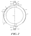
- FIG. 2 illustrates a cross sectional view of a steam conduit 2 having transmitting and receiving transducer assemblies, 12, 22 mounted thereon in accordance with one aspect of the present invention.
- the conduit may have a diameter of approximately thirty centimeters and a wall thickness of about one centimeter operative to contain steam at a pressure of about 10132.5 hPa to 15198.75 hPa (about ten to fifteen atmospheres) at a temperature of for example, 200° Celsius.
- each transducer assembly includes an ultrasonic signal source 12a such as a piezoelectric crystal, piezotransducer array or other vibration generating source, and this is attached to a wedge 12b for coupling to the conduit 4.
- the wedge 12b is urged against the conduit by a steel band or other clamping mechanism shown schematically by 12c to cinch it down into firm contact with the conduit wall.
- a mounting block secured by such a band may also be used, in which case the block may further include various screws for tightening down and aligning the transducer.
- the installation is preferably effected with a high precision clamp fixture - for example having two contact points to fix the transducer assembly against sliding or misalignment. Proper orientation may be achieved in the field by first scribing a line along the surface of the conduit on the diameter, and also providing a similar central line or marking 30 scribed on each of the coupling wedges 12b, 22b.
- the wedges are placed in an exact orientation along the axis by aligning their centering marks with the diametral center line of the conduit, and are clamped in position. This positions both transducers in a common plane, enhancing the received signal.
- the wedge/pipe contact area is a thin line or region, and the two assemblies are aligned parallel to each other within about five degrees. Pipe seams are to be avoided in the mounting region.
- the vertically polarized shear wave coupled into the pipe follows a skipping path as shown in Figure 1 which remains coherent for a distance of several skip lengths along the wall, energizing the wall to launch a narrow signal beam in a diametral plane across to the opposing transducer.
- the cylindrical curvature of the pipe aids in focusing and receiving this beam.
- the wedge 12b. 22b can be relatively narrow and its primary beam stays centered in the required plane and couples well into the gas, while shear waves of horizontal polarization SH spread laterally in the conduit, and are coupled into the fluid with very low efficiency. These horizontally polarized shear waves produce a cross-talk signal in the conduit wall that appears to propagate like Rayleigh waves R to the opposing transducer.
- the wedges 12b, 22b and their respective transducing crystals when acting as receivers are relatively inefficient at picking up and converting such laterally directed energy, so that the signal received from the vertically polarized signal reflecting portion of the wall is relatively strong and is distinguishable above the noise.
- the surface region of the conduit 4 between the two sets of transducers is preferably covered with a couplant or material G ( Figures 1A, 1B ) into which the crosstalk or Rayleigh wave energy R escapes, resulting in a high attenuation of this short circuit noise.
- a couplant or material G Figures 1A, 1B
- An additional structure such as a clamping shell ( Figures 1A, 1B ) or block B may be placed over the material G to further absorb the energy coupled out of the pipe or to contain and stabilize the layer of couplant over time.
- the figure illustrates energy circulating in one direction around the pipe from transducer 12 toward transducer 22; however, it will be appreciated that the crosstalk is launched substantially uniformly in both directions around the circumference, and, moreover, that each transducer may be actuated to transmit and receive so that similar wave energy propagates from transducer assembly 22 toward transducer assembly 12.
- FIGS 2A and 2B illustrate an experimental system set up to evaluate the amplitude of the fluid-borne portion of the signal and to simulate the transit path component through a steel wall and an air gap at atmospheric pressure.
- a 152.4 mm (six inch) diameter pipe was cut through along a central axial plane, and the two hemicylindroid shells were reconnected using wooden strips which sealed the interior while blocking short circuit noise from passing between the two transducers.
- the pipe was filled with air at atmospheric pressure.
- Transducer assemblies 12, 22 were centered and clamped to the conduit by clamp assemblies (not shown) to effect the vertically polarized shear wave transmission and reception geometry as illustrated in Figures 1 and 2 above. By acoustically disconnecting the two hemicylindrical surfaces, crosstalk was eliminated, permitting the evaluation of the received signals in a quiet environment. Measurements were taken at different transducer spacings.
- Figures 3A and 3B show the received signal for transducers separations of three inches ( Figure 3A ) and six inches ( Figure 3B ) along the axis of the 152.4 mm (six-inch) diameter pipe.
- the received signal was clearly defined.
- the further-apart transducer separation surprisingly had an amplitude almost twice as great as the more closely-spaced arrangement.
- a region of enhanced signal strength appeared at greater distance, vividly demonstrating the improvement obtained by energizing the conduit wall with a skipping signal.
- Applicant utilized such a composite array transducer, illustrated schematically in Figure 2C .
- This transducer construction produced an output with no side lobes, and together with the system architecture described in respect of Figures 1 and 2 above, produced a received signal of exceptional quality in a clamp-on air system.
- the high sensitivity of the transducer allowed clear reception of the transmitted tone burst signal through the air and pipe walls at ambient pressure, as shown in Figures 3A, 3B .
- the lack of the lateral mode further prevented generation of unwanted crosstalk noise emanating from the transmitter.
- the array transducer 32a was constructed as shown in Figure 2C . Its architecture was modified from constructions commonly employed for ultrasound and medical imaging technology. As shown in Figure 2C , this transducer 32a utilized a transducer element 60 which was fabricated as an array of active cells 61 by sawing grooves in a larger element in a checkerboard pattern with channels or grooves cut substantially between the adjacent cells to isolate each one from the other. The channels cut between adjacent cells 61 were filled with potting material so that the element 60 formed a continuous block while de-coupling the individual cells from each other.
- the transducing element 60 was thus formed of a piezoelectric composite construction, giving it the strength to undergo powerful actuation without fracture, and the stiffness and acoustic impedance to operate at high frequency and couple into the wedge or pipe.
- This construction like the VCSEL construction used to allow single mode lasers to be formed as an array of small elements, permitted the beam quality to be defined by the size of the small cells 61, while still energizing a large surface area with substantial signal power.
- the element 60 was fitted in a mounting to form a transducer with a disk-shaped emitter face that was actuated with substantially uniform power across its area by the multitude of individual cells 61. Each cell was dimensioned so that its mechanical resonance was tuned to the 500 kHz driving frequency.
- the cell array is configured to not support other nearby mechanical modes so that a broad single band response of defined spectral characteristics and compatible with coherent driving signals is applied to the transducer output face.
- the output forms a single broad band without a dip, so the transducer output was free of side lobes.
- the resulting ultrasonic wave is coupled into the test conduit ( Figures 2A, 2B ).
- transducer assemblies in order to measure an unperturbed flow, it is desirable to mount the transducer assemblies away from any existing flow obstructions such as shedding bodies or special by-pass arrangements that may have been installed for other metering applications in the past, and away from, or at a defined distance from, known flow disturbances such as elbows.
- damping material, or coupling material in a damping structure to regions of the conduit located outside of the segment between transducers so as to attenuate system background noise traveling in the conduit at large.
- the invention as set forth above was also applied to the highly noisy conditions of an operating steam plant and the received signals were processed to determine flow measurements of steam at a pressure of 1 ⁇ 3444 MPa (about 195 psig) and temperature of 208°C 407°F.
- Composite transducers as described above were attached top a standard intervalometer /driver flow meter, a Panametrics model GS868 meter with suitable software for clamp-on applications, and measurements were made over a period of forty minutes as the mass flow rate varied between about 0 ⁇ 4536 tons/hour and 2 ⁇ 7216 tons/hour (about 1000 pounds/hour and 6000 pounds/hour) in a 101 ⁇ 6 mm (four inch) pipe.
- the measurements were compared against measurements simultaneously
- the measurements were compared against measurements simultaneously taken by a previously installed vortex metering system.
- FIG. 4 shows the results of this test. As shown, the clamp-on measurements of the present invention (dotted graph) agreed with the vortex measurements (solid graph) obtained from the more costly installed measurement system.
- mounting block employed to clamp the transducer assembly against the conduit may itself be thermally insulated or offset from the conduit, and may thus provide a sink to actively cool the transducer or wedge.
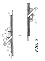
- Figure 5 shows a schematic view, in section, of a conduit 2 and two thermally insulated clamp-on transducer/mounting assemblies 50.
- the clamp-on assembly 50 includes a clamp-on mounting block 55 that secures the transducer or wedge assembly 60 in contact with the conduit.
- the block 55 preferably has a surface 57, which is prefeably curved to a contour to match the conduit 2, and is mounted on the conduit over a layer of damping material 59 as described above.
- the damping material 59 may include a layer of coupling grease or gel 59a, and a cover layer of fiberglass fabric or the like 59b which stabilizes the gel or grease for long term operation at high temperature.
- Through channels 56 may be provided through the block, or or other suitable grooves or guides may be provided on its upper surface, to received clamping bands passed around the conduit, or the block may be otherwise secured to the conduit by chains, straps or U-bolts so it is rigidly affixed and maintains its position.
- the shear wave transducer assembly 60 fits through an aligned groove or bore 62 in the block 55. This precisely orients the transducer and is shaped so the block thermally contacts the transducer assembly. While the block 55 is separated from the conduit by the damping layer 59, a window is provided in that layer through which the transducer assembly contacts the pipe wall directly.
- the fabric and gel/grease have relatively low thermal conductivity, and applicant has found that for a steam conduit at about 200 °C, the block itself remains about 50 °C cooler for each gel/fabric layer 59a,59b.
- the block cools the transducer assembly, providing a much greater heat dissipation area than a common coupling rod, without the acoustic degradation that a large-dimensioned rod would introduce.
- the block 55 provides greatly enhanced cooling and further serves to provide a lower operating temperature for both the transducer element and the polymer wedge. Additional layers or pads of damping material or fabric 59d may be provided, with further gel or grease 59c between successive layers to enhance transducer cooling on hot conduits, or reduce transducer cooling on cold or cryo conduits. In these constructions where the damping material is used to thermally insulate the mounting platform, care should be exercised to assure that alignment between the two transducers is not impaired.
- the invention has been described above with respect to the measurement of a fluid of low density or acoustic impedance.
- the various embodiments involve novel arrangements wherein the transmitting and receiving transducers are aligned and configured to provide and capture a signal of enhanced energy level and SNR to resolve flow velocity with dependable and effective resolution despite the conduit noise and low signal which generally afflict such fluid systems.
- the invention thus enables one to measure several fluids which have been previously inaccessible to effective clamp-on measurement, including, for example, low molecular weight hydrocarbons, low pressure steam, flare gas, or other gases.
- the array architecture of the preferred composite transducer construction allows one to fabricate arrays which are energized by electrodes to directly produce the desired shear wave signals, and these may be attached or even cemented directly to the pipe without requiring a shear wave wedge when the system temperature is compatible with the transducer material, e.g., well below 232 ⁇ 22°C (about 450°F) for piezoelectric ceramic composites.
- the transducer material e.g., well below 232 ⁇ 22°C (about 450°F) for piezoelectric ceramic composites.
- advantage may be made of the individual cell outputs to perform more complex filtering to remove noise and cross-talk in the received signal.
- the mounting to thermally isolate a transducer holding block or plate adds further advantages for high temperature systems where noise has heretofor prevented effective clamp-on measurement.
Landscapes
- Physics & Mathematics (AREA)
- Electromagnetism (AREA)
- Fluid Mechanics (AREA)
- General Physics & Mathematics (AREA)
- Measuring Volume Flow (AREA)
Claims (8)
- Ultraschall-Messsystem (10) zum Messen des Durchflusses eines Fluids, wie z.B. Gas oder Dampf, in einem Kanal (2), wobei ein solches System aufweist:einen Kanal (2);eine erste Ultraschallsignal-Wandleranordnung (12), die außen auf die Kanalwand geklemmt, konfiguriert und ausgerichtet ist, um einen Bereich der Kanalwand mit einem vertikal polarisierten Scherungswellen-Energieimpuls zu erregen, um ein Ultraschallsignal in der Wand des Kanals als ein axial wanderndes Übersprungsignal zu starten, um dadurch einen Bereich der Kanalwand anzuregen, Mode-gewandelte Signalenergie entlang einem Ausbreitungspfad durch das in dem Kanal strömende Fluid zu starten;eine zweite Ultraschallsignal-Wandleranordnung (22), die außen auf den Kanal (2) an einer Stelle über den Kanal hinweg von dem ersten Ultraschallsignalwandler festgeklemmt und in dem Ausbreitungspfad des Mode-gewandelten Signals angeordnet ist, wobei die zweite Ultraschallwandleranordnung zu dem Ausbreitungspfad durch das Fluid in dem Kanal (2) so ausgerichtet ist, dass beide Wandler (12, 22) in einer gemeinsamen Ebene positioniert sind, wobei der zweite Ultraschallwandler (22) so betrieben werden kann, dass er entlang dem Ausbreitungspfad empfangene Signalenergie repolarisiert, um effektiv im Signalempfang zu unterscheiden und eine Durchlaufzeitmessung bei Vorhandensein von Kanalgeräusch und Kurzschlussenergie durchzuführen;dadurch gekennzeichnet, dass das System ferner enthält:ein Dämpfungsmaterial zwischen den ersten (12) und den zweiten (22) Ultraschallwandleranordnungen zum Beseitigen von Kurzschlussgeräusch aus dem Kanal (2); undeinen Befestigungsblock, der den ersten Ultraschallwandler (12) an dem Kanal (2) befestigt, wobei der Befestigungsblock thermisch von dem Kanal (2) durch das Dämpfungsmaterial isoliert ist, und thermisch mit dem ersten Ultraschallwandler (12) in Kontakt steht, um als eine Wärmeabfuhr für diesen zu dienen.
- System nach Anspruch 1, wobei das Dämpfungsmaterial Übersprechen abschwächt.
- System nach einem der vorstehenden Ansprüche, wobei der Wandler (12) ein Single-Mode-Wandler ist.
- System nach einem der vorstehenden Ansprüche, in welcher jede Wandleranordnung (12, 22) ein Array aktiver Zellen aufweist.
- System nach einem der vorstehenden Ansprüche, wobei das Fluid Dampf oder Abfackelgas ist.
- System nach einem der vorstehenden Ansprüche, wobei die Wandleranordnungen aus Materialien für einen Betrieb auf einem Kanal von angenähert 200 °C ausgebildet sind.
- System nach einem der vorstehenden Ansprüche, wobei die erste Wandleranordnung (12) einkoppelt:(a) ein Signal bei einer Frequenz zwischen etwa 50 kHz und 1 MHz bei einem steilen Winkel zum Überspringen in die Kanalwand oder(b) ein vertikal polarisiertes Scherungswellensignal bei einer Frequenz zwischen etwa 50 kHz und 1 MHz in der Kanalwand.
- System nach Anspruch 1, wobei der Ultraschallsignal-Quellenwandler (12) und der Empfangswandler (22) etwa um einen Durchmesser entlang der Kanalachse in Abstand versetzt angeordnet sind sind.
Applications Claiming Priority (3)
| Application Number | Priority Date | Filing Date | Title |
|---|---|---|---|
| US12735399P | 1999-04-01 | 1999-04-01 | |
| US127353P | 1999-04-01 | ||
| PCT/US2000/008518 WO2000060317A1 (en) | 1999-04-01 | 2000-03-31 | Clamp-on ultrasonic flow meter for low density fluids |
Publications (2)
| Publication Number | Publication Date |
|---|---|
| EP1173733A1 EP1173733A1 (de) | 2002-01-23 |
| EP1173733B1 true EP1173733B1 (de) | 2011-05-18 |
Family
ID=22429683
Family Applications (1)
| Application Number | Title | Priority Date | Filing Date |
|---|---|---|---|
| EP00919924A Expired - Lifetime EP1173733B1 (de) | 1999-04-01 | 2000-03-31 | Aufsteckbarer ultraschall-durchflussaufnehmer für flüssigkeiten niedriger dichte |
Country Status (4)
| Country | Link |
|---|---|
| US (2) | US6626049B1 (de) |
| EP (1) | EP1173733B1 (de) |
| AT (1) | ATE510189T1 (de) |
| WO (1) | WO2000060317A1 (de) |
Cited By (5)
| Publication number | Priority date | Publication date | Assignee | Title |
|---|---|---|---|---|
| US9816847B2 (en) | 2014-09-05 | 2017-11-14 | Azbil Corporation | Ultrasonic flowmeter and method for measuring flow |
| DE102017004038A1 (de) | 2017-02-03 | 2018-08-09 | Diehl Metering Gmbh | Ultraschallzähler und Verfahren zur Erfassung einer Durchflussgröße |
| DE102017006909A1 (de) * | 2017-07-20 | 2019-01-24 | Diehl Metering Gmbh | Messmodul zur Ermittlung einer Fluidgröße |
| DE102020002834A1 (de) | 2020-05-12 | 2021-11-18 | Diehl Metering Gmbh | Messeinrichtung zur Ermittlung einer Fluidgröße |
| US20220113175A1 (en) * | 2019-01-30 | 2022-04-14 | Labtrino Ab | Coupling Member for Clamp on Flow Metering |
Families Citing this family (110)
| Publication number | Priority date | Publication date | Assignee | Title |
|---|---|---|---|---|
| EP1173733B1 (de) * | 1999-04-01 | 2011-05-18 | Panametrics, Inc. | Aufsteckbarer ultraschall-durchflussaufnehmer für flüssigkeiten niedriger dichte |
| JP3935356B2 (ja) * | 2001-02-05 | 2007-06-20 | サーパス工業株式会社 | 超音波流量計 |
| JP2002365106A (ja) * | 2001-04-02 | 2002-12-18 | Kazumasa Onishi | 流量測定装置及びクランプオン型超音波流量計 |
| US7474966B2 (en) * | 2002-01-23 | 2009-01-06 | Expro Meters. Inc | Apparatus having an array of piezoelectric film sensors for measuring parameters of a process flow within a pipe |
| EP1567833A2 (de) * | 2002-11-12 | 2005-08-31 | CiDra Corporation | Apparat mit einer reihe von piezoelektrischen film sensoren zur messung von parametern eines prozessflusses in einem rohr |
| DE10254054A1 (de) * | 2002-11-19 | 2004-06-03 | Endress + Hauser Flowtec Ag, Reinach | Vorrichtung zur Bestimmung und/oder Überwachung des Volumen- und/oder des Massendurchflusses eines Mediums |
| US20040123666A1 (en) * | 2002-12-31 | 2004-07-01 | Ao Xiaolei S. | Ultrasonic damping material |
| US7146864B2 (en) | 2003-03-04 | 2006-12-12 | Cidra Corporation | Apparatus having a multi-band sensor assembly for measuring a parameter of a fluid flow flowing within a pipe |
| WO2005001394A2 (en) | 2003-06-06 | 2005-01-06 | Cidra Corporation | A portable flow measurement apparatus having an array of sensors |
| US7194907B2 (en) | 2003-06-16 | 2007-03-27 | R/D Tech Instruments Inc. | Method for measuring part thickness having an external coating using impedance matching delay lines |
| WO2005054789A1 (en) | 2003-07-08 | 2005-06-16 | Cidra Corporation | Method and apparatus for measuring characteristics of core-annular flow |
| CA2537800C (en) | 2003-08-08 | 2013-02-19 | Cidra Corporation | Piezocable based sensor for measuring unsteady pressures inside a pipe |
| KR20100127321A (ko) * | 2003-09-05 | 2010-12-03 | 마이크로 모우션, 인코포레이티드 | 유량계 필터 시스템 및 방법 |
| US7171315B2 (en) | 2003-11-25 | 2007-01-30 | Cidra Corporation | Method and apparatus for measuring a parameter of a fluid flowing within a pipe using sub-array processing |
| JP2005156401A (ja) * | 2003-11-27 | 2005-06-16 | Fuji Electric Systems Co Ltd | クランプオン型ドップラー式超音波流速分布計 |
| US7152003B2 (en) | 2003-12-11 | 2006-12-19 | Cidra Corporation | Method and apparatus for determining a quality metric of a measurement of a fluid parameter |
| EP1559999A1 (de) | 2004-01-30 | 2005-08-03 | Fuji Electric Systems Co., Ltd. | Keil und keilförmige Einheit für Ultraschalldopplerdurchflussmesser |
| US7096135B2 (en) * | 2004-03-12 | 2006-08-22 | Panametrics, Inc. | Method and system for calculating the transit time of an ultrasonic pulse |
| US7367239B2 (en) | 2004-03-23 | 2008-05-06 | Cidra Corporation | Piezocable based sensor for measuring unsteady pressures inside a pipe |
| US7058521B2 (en) * | 2004-03-26 | 2006-06-06 | Panametrics, Inc. | Low power ultrasonic flow meter |
| US7426852B1 (en) | 2004-04-26 | 2008-09-23 | Expro Meters, Inc. | Submersible meter for measuring a parameter of gas hold-up of a fluid |
| WO2005116637A2 (en) | 2004-05-17 | 2005-12-08 | Cidra Corporation | Apparatus and method for measuring the composition of a mixture |
| US20060012491A1 (en) * | 2004-07-14 | 2006-01-19 | Mahowald Peter H | Utility meter reading system |
| US20060027015A1 (en) * | 2004-07-23 | 2006-02-09 | Tavlarides Lawrence L | Method and apparatus for estimating solids concentration in slurries |
| WO2006130499A2 (en) | 2005-05-27 | 2006-12-07 | Cidra Corporation | An apparatus and method for fiscal measuring of an aerated fluid |
| US7503227B2 (en) | 2005-07-13 | 2009-03-17 | Cidra Corporate Services, Inc | Method and apparatus for measuring parameters of a fluid flow using an array of sensors |
| US7152490B1 (en) | 2005-08-15 | 2006-12-26 | Daniel Measurement And Control, Inc. | Methods for determining transducer delay time and transducer separation in ultrasonic flow meters |
| US20070151363A1 (en) * | 2005-12-30 | 2007-07-05 | Honeywell International Inc. | Non-invasive sensing technique for measuring gas flow and temperature |
| RU2313068C2 (ru) * | 2006-02-01 | 2007-12-20 | Закрытое акционерное общество "УЛЬТРАМЕР"-ЗАО "УЛЬТРАМЕР" | Способ измерения расхода газа в трубопроводах и устройство для его осуществления |
| DE102006012114A1 (de) * | 2006-03-14 | 2007-09-20 | Endress + Hauser Flowtec Ag | Vorrichtung zur Bestimmung und/oder Überwachung des Volumen- oder des Massedurchflusses eines Mediums in einer Rohrleitung |
| DE102006062705B4 (de) * | 2006-03-30 | 2015-07-30 | Krohne Ag | Ultraschalldurchflußmeßgerät |
| US7762118B2 (en) * | 2006-05-05 | 2010-07-27 | The University Of Southern Mississippi | Auto-positioning ultrasonic transducer system |
| US7624650B2 (en) | 2006-07-27 | 2009-12-01 | Expro Meters, Inc. | Apparatus and method for attenuating acoustic waves propagating within a pipe wall |
| WO2008013957A1 (en) * | 2006-07-27 | 2008-01-31 | Cidra Corporation | Apparatus and method for attenuating acoustic waves in propagating within a pipe wall |
| US7624651B2 (en) * | 2006-10-30 | 2009-12-01 | Expro Meters, Inc. | Apparatus and method for attenuating acoustic waves in pipe walls for clamp-on ultrasonic flow meter |
| US7673526B2 (en) * | 2006-11-01 | 2010-03-09 | Expro Meters, Inc. | Apparatus and method of lensing an ultrasonic beam for an ultrasonic flow meter |
| EP2092278A2 (de) * | 2006-11-09 | 2009-08-26 | Expro Meters, Inc. | Vorrichtung und verfahren zur messung eines strömungsparameters in einem innendurchgang eines länglichen körpers |
| US8061186B2 (en) | 2008-03-26 | 2011-11-22 | Expro Meters, Inc. | System and method for providing a compositional measurement of a mixture having entrained gas |
| EP2269010B1 (de) * | 2008-04-10 | 2019-08-14 | Expro Meters, Inc. | Vorrichtung zur dämpfung von ultraschallwellenverbreitung in einer rohrwand |
| US7963177B2 (en) * | 2008-04-10 | 2011-06-21 | Expro Meters, Inc. | Apparatus for attenuating ultrasonic waves propagating within a pipe wall |
| WO2009149361A1 (en) | 2008-06-05 | 2009-12-10 | Expro Meters, Inc. | Method and apparatus for making a water cut determination using a sequestered liquid-continuous stream |
| WO2010003063A2 (en) * | 2008-07-03 | 2010-01-07 | Expro Meters, Inc. | Apparatus for attenuating ultrasonic waves propagating within a pipe wall |
| DE102008039464A1 (de) * | 2008-08-25 | 2010-03-04 | Endress + Hauser Flowtec Ag | Mehrschichtiges Messrohrstück zur akustischen Dämpfung von Rohrwellen |
| US7832282B2 (en) * | 2008-11-05 | 2010-11-16 | General Electric Company | Ultrasonic flow measurement system and method |
| US7658114B1 (en) | 2008-11-17 | 2010-02-09 | General Electric Company | Ultrasonic flow meter |
| US8763693B2 (en) * | 2008-12-05 | 2014-07-01 | Cameron International Corporation | Sub-sea chemical injection metering valve |
| US7703337B1 (en) * | 2009-02-27 | 2010-04-27 | Murray F Feller | Clamping arrangements for a transducer assembly having a piezoelectric element within a foam body |
| US7942068B2 (en) * | 2009-03-11 | 2011-05-17 | Ge Infrastructure Sensing, Inc. | Method and system for multi-path ultrasonic flow rate measurement |
| US8945066B2 (en) | 2009-11-06 | 2015-02-03 | Crisi Medical Systems, Inc. | Medication injection site and data collection system |
| US9101534B2 (en) | 2010-04-27 | 2015-08-11 | Crisi Medical Systems, Inc. | Medication and identification information transfer apparatus |
| US9514131B1 (en) | 2010-05-30 | 2016-12-06 | Crisi Medical Systems, Inc. | Medication container encoding, verification, and identification |
| US10492991B2 (en) | 2010-05-30 | 2019-12-03 | Crisi Medical Systems, Inc. | Medication container encoding, verification, and identification |
| WO2012005734A1 (en) * | 2010-07-09 | 2012-01-12 | Micro Motion, Inc. | A vibrating meter including a damped meter component |
| US8978481B2 (en) * | 2010-09-09 | 2015-03-17 | Baker Hughes Incorporated | Simultaneous ultrasonic cross-correlation and transit time measurements for multiphase flow rate analysis |
| CN103429348B (zh) * | 2011-01-21 | 2016-03-09 | 拜奥-多特公司 | 具有纵向变换器和可替换毛细管的压电分配器 |
| WO2013105987A2 (en) | 2011-02-15 | 2013-07-18 | Hemosonics, Llc | Characterization of blood hemostasis and oxygen transport parameters |
| US9078809B2 (en) | 2011-06-16 | 2015-07-14 | Crisi Medical Systems, Inc. | Medication dose preparation and transfer system |
| US9744298B2 (en) | 2011-06-22 | 2017-08-29 | Crisi Medical Systems, Inc. | Selectively controlling fluid flow through a fluid pathway |
| US10293107B2 (en) | 2011-06-22 | 2019-05-21 | Crisi Medical Systems, Inc. | Selectively Controlling fluid flow through a fluid pathway |
| AU2012364830B2 (en) * | 2012-01-12 | 2014-10-02 | Micro Motion, Inc. | Meter having banded shroud |
| CN103470201B (zh) | 2012-06-07 | 2017-05-10 | 通用电气公司 | 流体控制系统 |
| WO2014035785A1 (en) * | 2012-08-27 | 2014-03-06 | Rensselaer Polytechnic Institute | Method and apparatus for acoustical power transfer and communication |
| US10143830B2 (en) | 2013-03-13 | 2018-12-04 | Crisi Medical Systems, Inc. | Injection site information cap |
| JP2014178202A (ja) * | 2013-03-14 | 2014-09-25 | Osaka Gas Co Ltd | 超音波流量計及び超音波流量測定方法 |
| US8955392B2 (en) * | 2013-03-15 | 2015-02-17 | Strain Measurement Devices, Inc. | Ultrasonic flowmeter with integrally formed acoustic noise attenuating feature |
| JP6161448B2 (ja) * | 2013-07-17 | 2017-07-12 | アズビル株式会社 | 超音波流量計及び超音波流量計用の超音波吸収体 |
| US9343898B2 (en) * | 2013-07-19 | 2016-05-17 | Texas Instruments Incorporated | Driver current control apparatus and methods |
| JP5971428B2 (ja) * | 2013-10-23 | 2016-08-17 | 富士電機株式会社 | 流体計測装置 |
| WO2015117263A1 (en) | 2014-02-04 | 2015-08-13 | General Electric Company | Ultrasonic flow meter clamp |
| KR102167810B1 (ko) * | 2014-04-17 | 2020-10-21 | 버킨 비.브이. | 초음파 유량계 |
| US9853394B2 (en) * | 2014-05-02 | 2017-12-26 | Itt Manufacturing Enterprises, Llc | Pressure-blocking feedthru with pressure-balanced cable terminations |
| JP2015230260A (ja) * | 2014-06-05 | 2015-12-21 | アズビル株式会社 | 超音波流量計及び超音波流量計の取付方法 |
| CA2952064C (en) | 2014-06-10 | 2020-04-07 | Soneter, Inc. | Sensor assembly |
| JP2015232519A (ja) | 2014-06-10 | 2015-12-24 | アズビル株式会社 | クランプオン式超音波流量計及び流量の計測方法 |
| JP6472617B2 (ja) * | 2014-08-06 | 2019-02-20 | 関西電力株式会社 | 気体用外付式超音波流量計及び気体流量計測方法 |
| US9505233B2 (en) | 2014-10-10 | 2016-11-29 | Becton, Dickinson And Company | Tensioning control device |
| ES2948459T3 (es) | 2014-10-10 | 2023-09-12 | Becton Dickinson Co | Dispositivo de etiquetado de jeringa |
| US9793029B2 (en) | 2015-01-21 | 2017-10-17 | Itt Manufacturing Enterprises Llc | Flexible, pressure-balanced cable assembly |
| US9726647B2 (en) | 2015-03-17 | 2017-08-08 | Hemosonics, Llc | Determining mechanical properties via ultrasound-induced resonance |
| JP6474682B2 (ja) * | 2015-05-14 | 2019-02-27 | 株式会社キーエンス | 超音波流量スイッチ |
| US9671270B2 (en) * | 2015-07-30 | 2017-06-06 | Daniel Measurement And Control, Inc. | Flow meter having electronic mount bracket assembly |
| US9810563B2 (en) * | 2015-07-30 | 2017-11-07 | Daniel Measurement And Control, Inc. | Flow meter having electronic enclosure assembly |
| US9448092B1 (en) | 2015-09-03 | 2016-09-20 | King Fahd University Of Petroleum And Minerals | Clamp-on ultrasonic fluid flow meter system |
| NL2015591B1 (en) * | 2015-10-09 | 2017-05-02 | Berkin Bv | Ultrasonic flow meter. |
| JP6582855B2 (ja) * | 2015-10-14 | 2019-10-02 | 東京電力ホールディングス株式会社 | 流量計測装置および流量計測方法 |
| US10591329B2 (en) * | 2016-06-14 | 2020-03-17 | Apator Miitors Aps | Reflector clamping member and use thereof |
| PL3485233T3 (pl) * | 2016-07-13 | 2020-11-02 | Gwf Messsysteme Ag | Przepływomierz ultradźwiękowy z kanałem pomiarowym |
| US9843113B1 (en) | 2017-04-06 | 2017-12-12 | Itt Manufacturing Enterprises Llc | Crimpless electrical connectors |
| US9941622B1 (en) | 2017-04-20 | 2018-04-10 | Itt Manufacturing Enterprises Llc | Connector with sealing boot and moveable shuttle |
| US10276969B2 (en) | 2017-04-20 | 2019-04-30 | Itt Manufacturing Enterprises Llc | Connector with sealing boot and moveable shuttle |
| JP6909100B2 (ja) * | 2017-08-25 | 2021-07-28 | アズビル株式会社 | 超音波流量計および超音波流量計測方法 |
| JP7056096B2 (ja) * | 2017-11-24 | 2022-04-19 | 富士電機株式会社 | 超音波流量測定構造 |
| DE102017130976A1 (de) | 2017-12-21 | 2019-06-27 | Endress+Hauser Flowtec Ag | Clamp-On-Ultraschall-Durchflussmessgerät und Verfahren zum Justieren des Clamp-On-Ultraschall-Durchflussmessgeräts |
| US10114000B1 (en) * | 2018-02-21 | 2018-10-30 | mIQroTech, LLC | Apparatus, system, and method for monitoring flow in a passage |
| JP6894863B2 (ja) * | 2018-03-14 | 2021-06-30 | 株式会社キーエンス | クランプオン式超音波流量センサ |
| JP6917929B2 (ja) * | 2018-03-14 | 2021-08-11 | 株式会社キーエンス | クランプオン式超音波流量センサ |
| JP6966963B2 (ja) * | 2018-03-14 | 2021-11-17 | 株式会社キーエンス | クランプオン式超音波流量センサ |
| CN108660309A (zh) * | 2018-06-08 | 2018-10-16 | 北京理工大学 | 一种输气管道焊接残余应力高能声束消减装置 |
| KR102026362B1 (ko) * | 2018-08-01 | 2019-09-27 | 서울대학교산학협력단 | Meta slab을 적용한 유속 측정용 초음파 트랜스듀서 |
| JP7160622B2 (ja) * | 2018-10-11 | 2022-10-25 | 株式会社キーエンス | クランプオン式超音波流量計 |
| DE102018132055B4 (de) * | 2018-12-13 | 2022-08-25 | Endress + Hauser Flowtec Ag | Ultraschallwandleranordnung einer Clamp-On-Ultraschall-Durchflussmessstelle, und eine Clamp-On-Ultraschall-Durchflussmessstelle sowie Verfahren zur Inbetriebnahme der Clamp-On-Ultraschall-Durchflussmessstelle |
| DE102018132053B4 (de) * | 2018-12-13 | 2022-08-25 | Endress+Hauser Flowtec Ag | Ultraschallwandleranordnung einer Clamp-On-Ultraschall-Durchflussmessstelle, und eine Clamp-On-Ultraschall-Durchflussmessstelle sowie Verfahren zur Inbetriebnahme der Clamp-On-Ultraschall-Durchflussmessstelle |
| JP6671522B2 (ja) * | 2019-01-30 | 2020-03-25 | 株式会社キーエンス | 超音波流量スイッチ |
| CN109931896B (zh) * | 2019-03-21 | 2021-08-03 | 浙江未来技术研究院(嘉兴) | 一种高温或低温被测管道壁厚检测方法、设备及系统 |
| CN110057414A (zh) * | 2019-04-09 | 2019-07-26 | 中国大唐集团科学技术研究院有限公司火力发电技术研究院 | 一种小管径封闭管道水流量超声波测量优化方法及装置 |
| CA3051376C (en) | 2019-08-06 | 2020-04-28 | Surface Solutions Inc. | Methane monitoring and conversion apparatus and methods |
| CN110455360B (zh) * | 2019-08-28 | 2021-08-06 | 杭州乾博科技有限公司 | 一种超声波水表 |
| JP7510682B2 (ja) * | 2020-12-22 | 2024-07-04 | 本多電子株式会社 | ガイド波式の超音波流量計 |
| TWI782450B (zh) * | 2021-03-19 | 2022-11-01 | 和旺昌噴霧股份有限公司 | 管路液體之監測裝置 |
| DE102022122181A1 (de) * | 2022-09-01 | 2024-03-07 | Krohne Ag | Verfahren zum Betreiben eines Ultraschalldurchflussmessgeräts und Ultraschalldurchflussmessgerät |
Family Cites Families (47)
| Publication number | Priority date | Publication date | Assignee | Title |
|---|---|---|---|---|
| US389419A (en) * | 1888-09-11 | Force-pump | ||
| US3894169A (en) | 1972-02-18 | 1975-07-08 | Rockwell International Corp | Acoustical damping structure and method of preparation |
| US4003252A (en) * | 1974-08-16 | 1977-01-18 | The Institutes Of Medical Sciences | Acoustical wave flowmeter |
| US4004461A (en) | 1975-11-07 | 1977-01-25 | Panametrics, Inc. | Ultrasonic measuring system with isolation means |
| US4164865A (en) * | 1977-02-22 | 1979-08-21 | The Perkin-Elmer Corporation | Acoustical wave flowmeter |
| US4174255A (en) * | 1977-05-06 | 1979-11-13 | The Babcock & Wilcox Company | Apparatus for locating defective nuclear fuel elements |
| US4320659A (en) * | 1978-02-27 | 1982-03-23 | Panametrics, Inc. | Ultrasonic system for measuring fluid impedance or liquid level |
| US4195517A (en) * | 1978-12-18 | 1980-04-01 | The Foxboro Company | Ultrasonic flowmeter |
| EP0036658B1 (de) * | 1980-03-25 | 1985-01-23 | Fuji Electric Co. Ltd. | Ultraschall-Messgerät zur Bestimmung der Strömung eines Mediums in einer Leitung |
| US4398424A (en) | 1980-12-16 | 1983-08-16 | Micro Pure Systems, Inc. | Ultrasonic sensing |
| US4417480A (en) * | 1981-06-02 | 1983-11-29 | Mapco, Inc. | Dampened ultrasonic transducer |
| US4467659A (en) * | 1982-08-12 | 1984-08-28 | Joseph Baumoel | Transducer having metal housing and employing mode conversion |
| US4630245A (en) * | 1983-07-15 | 1986-12-16 | Introtek Corporation | Non-contacting liquid level detection system |
| US4536673A (en) * | 1984-01-09 | 1985-08-20 | Siemens Aktiengesellschaft | Piezoelectric ultrasonic converter with polyurethane foam damper |
| US4598593A (en) * | 1984-05-14 | 1986-07-08 | The United States Of America As Represented By The United States Department Of Energy | Acoustic cross-correlation flowmeter for solid-gas flow |
| GB8526628D0 (en) * | 1985-10-29 | 1985-12-04 | Acumet Precision Instr Ltd | Measurement of specific gravity |
| NO161882C (no) * | 1987-04-24 | 1989-10-04 | Norske Stats Oljeselskap | Med ultralyd arbeidende transduseranordning for maaling avstroemningshastigheten til et fluidum i et roer. |
| FR2645583B1 (fr) * | 1989-04-06 | 1991-07-12 | Inst Francais Du Petrole | Methode et dispositif de prospection sismique dans des puits et notamment des puits devies |
| GB8913173D0 (en) | 1989-06-08 | 1989-07-26 | Pipetex Limited | Pipe protection |
| US5131278A (en) * | 1989-06-13 | 1992-07-21 | Joseph Baumoel | Mounting structure for transducers with sonic-energy absorbing means |
| US5000478A (en) * | 1990-03-15 | 1991-03-19 | Monroe Auto Equipment Company | Shock absorber with Doppler fluid velocity sensor |
| DE59007347D1 (de) * | 1990-05-19 | 1994-11-03 | Flowtec Ag | Messerwertaufnehmer für ein Ultraschall-Volumendurchfluss-Messgerät. |
| US5179862A (en) | 1990-06-29 | 1993-01-19 | Panametrics, Inc. | Snap-on flow measurement system |
| US5275060A (en) * | 1990-06-29 | 1994-01-04 | Panametrics, Inc. | Ultrasonic transducer system with crosstalk isolation |
| DE4028315A1 (de) * | 1990-09-06 | 1992-03-12 | Siemens Ag | Ultraschallwandler fuer die laufzeitmessung von ultraschall-impulsen in einem gas |
| US5178902A (en) * | 1990-12-21 | 1993-01-12 | Shaw Industries Ltd. | High performance composite coating |
| US5437194A (en) * | 1991-03-18 | 1995-08-01 | Panametrics, Inc. | Ultrasonic transducer system with temporal crosstalk isolation |
| JPH0518944A (ja) | 1991-07-09 | 1993-01-26 | Mitsubishi Electric Corp | 超音波探触子 |
| US5343737A (en) * | 1992-09-22 | 1994-09-06 | Joseph Baumoel | Method and apparatus for leak detection and pipeline temperature modelling method and apparatus |
| US5456114A (en) * | 1993-04-23 | 1995-10-10 | Panametrics, Inc. | Elastic wave sensing system |
| US5307830A (en) * | 1993-05-18 | 1994-05-03 | Welker Engineering Company | Flow distribution method and apparatus reducing downstream turbulence |
| US5353873A (en) * | 1993-07-09 | 1994-10-11 | Cooke Jr Claude E | Apparatus for determining mechanical integrity of wells |
| GB2282297B (en) * | 1993-09-23 | 1998-03-11 | Holroyd Instr Ltd | Improved resonant acoustic emission transducer |
| US5473934A (en) * | 1993-10-13 | 1995-12-12 | Cobb; Wesley | Ultrasonic fluid composition monitor |
| US5332943A (en) * | 1993-10-21 | 1994-07-26 | Bhardwaj Mahesh C | High temperature ultrasonic transducer device |
| DE59510158D1 (de) * | 1995-09-28 | 2002-05-16 | Endress Hauser Gmbh Co | Ultraschallwandler |
| US5714687A (en) * | 1995-10-31 | 1998-02-03 | Dunegan; Harold L. | Transducer for measuring acoustic emission events |
| US6047602A (en) | 1996-10-29 | 2000-04-11 | Panametrics, Inc. | Ultrasonic buffer/waveguide |
| US6026693A (en) * | 1997-06-04 | 2000-02-22 | Baumoel; Douglas S. | Pipe spool section having square or rectangular cross-section for clamp on transducer and method for flow measurement |
| US6382033B1 (en) * | 1997-10-09 | 2002-05-07 | Krohne Mebtechnik Gmbh & Co. Kg | Sound damper for ultrasonic waves |
| JP3501948B2 (ja) | 1998-06-12 | 2004-03-02 | 株式会社 日立インダストリイズ | 超音波腐食診断法とその装置 |
| US6065350A (en) * | 1998-07-10 | 2000-05-23 | Panametrics, Inc. | Flow measurement system with guided signal launched in lowest mode |
| JP3569799B2 (ja) * | 1998-12-17 | 2004-09-29 | 株式会社泉技研 | 超音波流量計 |
| US6293156B1 (en) * | 1999-01-22 | 2001-09-25 | Panametrics, Inc. | Coherent multi-path flow measurement system |
| EP1173733B1 (de) * | 1999-04-01 | 2011-05-18 | Panametrics, Inc. | Aufsteckbarer ultraschall-durchflussaufnehmer für flüssigkeiten niedriger dichte |
| CA2294679C (en) * | 2000-01-06 | 2007-10-09 | Shishiai-Kabushikigaisha | Acoustic damping pipe cover |
| US20040123666A1 (en) | 2002-12-31 | 2004-07-01 | Ao Xiaolei S. | Ultrasonic damping material |
-
2000
- 2000-03-31 EP EP00919924A patent/EP1173733B1/de not_active Expired - Lifetime
- 2000-03-31 AT AT00919924T patent/ATE510189T1/de not_active IP Right Cessation
- 2000-03-31 WO PCT/US2000/008518 patent/WO2000060317A1/en not_active Ceased
- 2000-03-31 US US09/539,976 patent/US6626049B1/en not_active Expired - Lifetime
-
2002
- 2002-12-23 US US10/329,256 patent/US7000485B2/en not_active Expired - Lifetime
Cited By (9)
| Publication number | Priority date | Publication date | Assignee | Title |
|---|---|---|---|---|
| US9816847B2 (en) | 2014-09-05 | 2017-11-14 | Azbil Corporation | Ultrasonic flowmeter and method for measuring flow |
| DE102017004038A1 (de) | 2017-02-03 | 2018-08-09 | Diehl Metering Gmbh | Ultraschallzähler und Verfahren zur Erfassung einer Durchflussgröße |
| US10989578B2 (en) | 2017-02-03 | 2021-04-27 | Diehl Metering Gmbh | Ultrasonic meter and method for sensing a flow variable |
| DE102017004038B4 (de) | 2017-02-03 | 2022-01-27 | Diehl Metering Gmbh | Ultraschallzähler und Verfahren zur Erfassung einer Durchflussgröße |
| DE102017006909A1 (de) * | 2017-07-20 | 2019-01-24 | Diehl Metering Gmbh | Messmodul zur Ermittlung einer Fluidgröße |
| US10775222B2 (en) | 2017-07-20 | 2020-09-15 | Diehl Metering Gmbh | Measurement device and method for determining a fluid flow in a measurement tube |
| US20220113175A1 (en) * | 2019-01-30 | 2022-04-14 | Labtrino Ab | Coupling Member for Clamp on Flow Metering |
| US11982559B2 (en) * | 2019-01-30 | 2024-05-14 | Labtrino Ab | Coupling member for clamp on flow metering |
| DE102020002834A1 (de) | 2020-05-12 | 2021-11-18 | Diehl Metering Gmbh | Messeinrichtung zur Ermittlung einer Fluidgröße |
Also Published As
| Publication number | Publication date |
|---|---|
| US6626049B1 (en) | 2003-09-30 |
| US20030172743A1 (en) | 2003-09-18 |
| EP1173733A1 (de) | 2002-01-23 |
| WO2000060317A1 (en) | 2000-10-12 |
| US7000485B2 (en) | 2006-02-21 |
| ATE510189T1 (de) | 2011-06-15 |
Similar Documents
| Publication | Publication Date | Title |
|---|---|---|
| EP1173733B1 (de) | Aufsteckbarer ultraschall-durchflussaufnehmer für flüssigkeiten niedriger dichte | |
| EP0935798B1 (de) | Ultraschallwellenpuffer oder - leiter | |
| US6293156B1 (en) | Coherent multi-path flow measurement system | |
| EP0212470B1 (de) | Gerät zur Messung der Charakteristiken fliessfähiger Stoffe unter Verwendung oberflächenerzeugter Volumenuntersuchungssignale | |
| US5962790A (en) | Ultrasonic path bundle and systems | |
| US5437194A (en) | Ultrasonic transducer system with temporal crosstalk isolation | |
| US4783997A (en) | Ultrasonic transducers for high temperature applications | |
| JP2944206B2 (ja) | 超音波流量計 | |
| US6343511B1 (en) | Ultrasonic path bundle and systems | |
| US8090131B2 (en) | Steerable acoustic waveguide | |
| US5515733A (en) | Ultrasonic transducer system with crosstalk isolation | |
| US9274090B2 (en) | Ultrasonic non-destructive testing | |
| WO1996022527A1 (en) | Bore probe for tube inspection with guided waves and method therefor | |
| US7185547B2 (en) | Extreme temperature clamp-on ultrasonic flowmeter transducer | |
| JPH06217395A (ja) | 単色超音波変換器 | |
| Cawley et al. | The use of large ultrasonic transducers to improve transmission coefficient measurements on viscoelastic anisotropic plates | |
| CN111912902B (zh) | 超声波探头及裂纹检测装置 | |
| JPS61132822A (ja) | 超音波流量計 | |
| JP2005180988A (ja) | 超音波流量計 | |
| US5408439A (en) | Monolithic construction of waveguide tubes | |
| JP2002250644A (ja) | クランプオン形超音波流量計における超音波送受波器 | |
| JP2978708B2 (ja) | 複合型斜角探触子 | |
| GB1425249A (en) | Ultrasonic testing apparatus | |
| SU1163252A1 (ru) | Ультразвуковой преобразователь дл измерени скорости поперечных ультразвуковых колебаний | |
| JPH05312611A (ja) | 透過式超音波流量計 |
Legal Events
| Date | Code | Title | Description |
|---|---|---|---|
| PUAI | Public reference made under article 153(3) epc to a published international application that has entered the european phase |
Free format text: ORIGINAL CODE: 0009012 |
|
| 17P | Request for examination filed |
Effective date: 20011102 |
|
| AK | Designated contracting states |
Kind code of ref document: A1 Designated state(s): AT BE CH CY DE DK ES FI FR GB GR IE IT LI LU MC NL PT SE |
|
| 17Q | First examination report despatched |
Effective date: 20041223 |
|
| GRAP | Despatch of communication of intention to grant a patent |
Free format text: ORIGINAL CODE: EPIDOSNIGR1 |
|
| GRAS | Grant fee paid |
Free format text: ORIGINAL CODE: EPIDOSNIGR3 |
|
| GRAA | (expected) grant |
Free format text: ORIGINAL CODE: 0009210 |
|
| AK | Designated contracting states |
Kind code of ref document: B1 Designated state(s): AT BE CH CY DE DK ES FI FR GB GR IE IT LI LU MC NL PT SE |
|
| REG | Reference to a national code |
Ref country code: GB Ref legal event code: FG4D |
|
| REG | Reference to a national code |
Ref country code: CH Ref legal event code: EP |
|
| REG | Reference to a national code |
Ref country code: IE Ref legal event code: FG4D |
|
| REG | Reference to a national code |
Ref country code: DE Ref legal event code: R096 Ref document number: 60045980 Country of ref document: DE Effective date: 20110630 |
|
| REG | Reference to a national code |
Ref country code: NL Ref legal event code: T3 |
|
| PG25 | Lapsed in a contracting state [announced via postgrant information from national office to epo] |
Ref country code: PT Free format text: LAPSE BECAUSE OF FAILURE TO SUBMIT A TRANSLATION OF THE DESCRIPTION OR TO PAY THE FEE WITHIN THE PRESCRIBED TIME-LIMIT Effective date: 20110919 Ref country code: SE Free format text: LAPSE BECAUSE OF FAILURE TO SUBMIT A TRANSLATION OF THE DESCRIPTION OR TO PAY THE FEE WITHIN THE PRESCRIBED TIME-LIMIT Effective date: 20110518 |
|
| PG25 | Lapsed in a contracting state [announced via postgrant information from national office to epo] |
Ref country code: FI Free format text: LAPSE BECAUSE OF FAILURE TO SUBMIT A TRANSLATION OF THE DESCRIPTION OR TO PAY THE FEE WITHIN THE PRESCRIBED TIME-LIMIT Effective date: 20110518 Ref country code: ES Free format text: LAPSE BECAUSE OF FAILURE TO SUBMIT A TRANSLATION OF THE DESCRIPTION OR TO PAY THE FEE WITHIN THE PRESCRIBED TIME-LIMIT Effective date: 20110829 Ref country code: BE Free format text: LAPSE BECAUSE OF FAILURE TO SUBMIT A TRANSLATION OF THE DESCRIPTION OR TO PAY THE FEE WITHIN THE PRESCRIBED TIME-LIMIT Effective date: 20110518 Ref country code: AT Free format text: LAPSE BECAUSE OF FAILURE TO SUBMIT A TRANSLATION OF THE DESCRIPTION OR TO PAY THE FEE WITHIN THE PRESCRIBED TIME-LIMIT Effective date: 20110518 Ref country code: GR Free format text: LAPSE BECAUSE OF FAILURE TO SUBMIT A TRANSLATION OF THE DESCRIPTION OR TO PAY THE FEE WITHIN THE PRESCRIBED TIME-LIMIT Effective date: 20110819 Ref country code: CY Free format text: LAPSE BECAUSE OF FAILURE TO SUBMIT A TRANSLATION OF THE DESCRIPTION OR TO PAY THE FEE WITHIN THE PRESCRIBED TIME-LIMIT Effective date: 20110518 |
|
| PG25 | Lapsed in a contracting state [announced via postgrant information from national office to epo] |
Ref country code: DK Free format text: LAPSE BECAUSE OF FAILURE TO SUBMIT A TRANSLATION OF THE DESCRIPTION OR TO PAY THE FEE WITHIN THE PRESCRIBED TIME-LIMIT Effective date: 20110518 |
|
| PLBE | No opposition filed within time limit |
Free format text: ORIGINAL CODE: 0009261 |
|
| STAA | Information on the status of an ep patent application or granted ep patent |
Free format text: STATUS: NO OPPOSITION FILED WITHIN TIME LIMIT |
|
| 26N | No opposition filed |
Effective date: 20120221 |
|
| PG25 | Lapsed in a contracting state [announced via postgrant information from national office to epo] |
Ref country code: IT Free format text: LAPSE BECAUSE OF FAILURE TO SUBMIT A TRANSLATION OF THE DESCRIPTION OR TO PAY THE FEE WITHIN THE PRESCRIBED TIME-LIMIT Effective date: 20110518 |
|
| REG | Reference to a national code |
Ref country code: DE Ref legal event code: R097 Ref document number: 60045980 Country of ref document: DE Effective date: 20120221 |
|
| PG25 | Lapsed in a contracting state [announced via postgrant information from national office to epo] |
Ref country code: MC Free format text: LAPSE BECAUSE OF NON-PAYMENT OF DUE FEES Effective date: 20120331 |
|
| REG | Reference to a national code |
Ref country code: CH Ref legal event code: PL |
|
| REG | Reference to a national code |
Ref country code: FR Ref legal event code: ST Effective date: 20121130 |
|
| REG | Reference to a national code |
Ref country code: IE Ref legal event code: MM4A |
|
| PG25 | Lapsed in a contracting state [announced via postgrant information from national office to epo] |
Ref country code: LI Free format text: LAPSE BECAUSE OF NON-PAYMENT OF DUE FEES Effective date: 20120331 Ref country code: FR Free format text: LAPSE BECAUSE OF NON-PAYMENT OF DUE FEES Effective date: 20120402 Ref country code: IE Free format text: LAPSE BECAUSE OF NON-PAYMENT OF DUE FEES Effective date: 20120331 Ref country code: CH Free format text: LAPSE BECAUSE OF NON-PAYMENT OF DUE FEES Effective date: 20120331 |
|
| PG25 | Lapsed in a contracting state [announced via postgrant information from national office to epo] |
Ref country code: LU Free format text: LAPSE BECAUSE OF NON-PAYMENT OF DUE FEES Effective date: 20120331 |
|
| PGFP | Annual fee paid to national office [announced via postgrant information from national office to epo] |
Ref country code: DE Payment date: 20150327 Year of fee payment: 16 Ref country code: NL Payment date: 20150326 Year of fee payment: 16 |
|
| PGFP | Annual fee paid to national office [announced via postgrant information from national office to epo] |
Ref country code: GB Payment date: 20150327 Year of fee payment: 16 |
|
| REG | Reference to a national code |
Ref country code: DE Ref legal event code: R119 Ref document number: 60045980 Country of ref document: DE |
|
| REG | Reference to a national code |
Ref country code: NL Ref legal event code: MM Effective date: 20160401 |
|
| GBPC | Gb: european patent ceased through non-payment of renewal fee |
Effective date: 20160331 |
|
| PG25 | Lapsed in a contracting state [announced via postgrant information from national office to epo] |
Ref country code: DE Free format text: LAPSE BECAUSE OF NON-PAYMENT OF DUE FEES Effective date: 20161001 Ref country code: NL Free format text: LAPSE BECAUSE OF NON-PAYMENT OF DUE FEES Effective date: 20160401 Ref country code: GB Free format text: LAPSE BECAUSE OF NON-PAYMENT OF DUE FEES Effective date: 20160331 |