EP1174018A1 - Tête pivotante pour tondeuse à fil - Google Patents
Tête pivotante pour tondeuse à fil Download PDFInfo
- Publication number
- EP1174018A1 EP1174018A1 EP01305046A EP01305046A EP1174018A1 EP 1174018 A1 EP1174018 A1 EP 1174018A1 EP 01305046 A EP01305046 A EP 01305046A EP 01305046 A EP01305046 A EP 01305046A EP 1174018 A1 EP1174018 A1 EP 1174018A1
- Authority
- EP
- European Patent Office
- Prior art keywords
- chassis
- trimmer
- housing
- cutter head
- respect
- Prior art date
- Legal status (The legal status is an assumption and is not a legal conclusion. Google has not performed a legal analysis and makes no representation as to the accuracy of the status listed.)
- Withdrawn
Links
- 238000002485 combustion reaction Methods 0.000 claims description 5
- 210000002105 tongue Anatomy 0.000 description 6
- 238000000034 method Methods 0.000 description 2
- 244000025254 Cannabis sativa Species 0.000 description 1
- 230000005540 biological transmission Effects 0.000 description 1
- 238000010276 construction Methods 0.000 description 1
- 230000000694 effects Effects 0.000 description 1
Images


Classifications
-
- A—HUMAN NECESSITIES
- A01—AGRICULTURE; FORESTRY; ANIMAL HUSBANDRY; HUNTING; TRAPPING; FISHING
- A01D—HARVESTING; MOWING
- A01D34/00—Mowers; Mowing apparatus of harvesters
- A01D34/835—Mowers; Mowing apparatus of harvesters specially adapted for particular purposes
- A01D34/84—Mowers; Mowing apparatus of harvesters specially adapted for particular purposes for edges of lawns or fields, e.g. for mowing close to trees or walls
Definitions
- the invention relates to walk-behind line trimmers.
- Walk-behind line trimmers typically include a body or chassis supporting an internal combustion engine.
- the engine usually includes a vertical crankshaft that is coupled to a cutter shaft to cause the cutter shaft to rotate in response to rotation of the crankshaft.
- a disk is mounted to the cutter shaft and rotates therewith.
- Plastic monofilament line is attached to the disk and is whipped around as the disk rotates to trim grass and other vegetation.
- the present invention provides a walk-behind trimmer including a chassis that is supported by a pair of wheels that are rotatable with respect to the chassis.
- a handle connects to the chassis to permit an operator to push and pull the trimmer along a portion of ground to be trimmed.
- a swivel bracket is pivotably mounted to the chassis.
- a housing is mounted to the swivel bracket and the swivel bracket and housing are pivotable together with respect to the chassis.
- the housing supports an internal combustion engine that includes an output shaft which is preferably the engine's crankshaft.
- the housing also supports a cutter head spaced from the output shaft.
- a sheave is mounted to each of the output shaft and cutter head for rotation therewith.
- a belt extends between the sheaves to transfer torque from the output shaft to the cutter head, and to cause rotation of the cutter head in response to rotation of the output shaft.
- both the cutter head and engine are mounted to the housing and supported by the swivel bracket, the position of the cutter head may be pivoted with respect to the chassis without changing the distance between the output shaft and the cutter head.
- the swivel bracket and housing are pivotable with respect to the chassis to permit a range of pivoting of the swivel bracket with respect to the chassis.
- the cutter head may be pivoted up to about 14° to the left and right. Pivoting the swivel bracket and housing may position a portion of the cutting line outboard of the wheels of the trimmer.
- a lock mechanism which may be wing nut or knob, locks the swivel bracket in position and resists rotation of the swivel bracket with respect to the chassis. Because the handle assembly is mounted to the chassis, the trimmer is easily handled by an operator regardless of the position of the cutter head.
- Fig. 1 is a perspective view of a walk-behind line trimmer embodying the present invention.
- Fig. 2 is an exploded illustration of the rear portion of the trimmer of Fig. 1.
- Fig. 3 is an exploded illustration of the front portion of the trimmer of Fig. 1.
- Fig. 4 is a rear perspective view of the trimmer of Fig. 1.
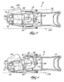
- Fig. 5 is a top view of the trimmer of Fig. 1 in a zero-swivel position.
- Fig. 6 is a top view of the trimmer of Fig. 1 in a full-swivel position to the left.
- Fig. 1 illustrates a walk-behind line trimmer 10.
- the rear end components of the trimmer 10 are best seen in Fig. 2.
- the trimmer includes a handle assembly 14 that is bolted to a chassis or wheel bracket 18.
- a pair of wheels 22 (only one of which is shown in Fig. 2) are mounted to the chassis 18 with suitable axles to permit rotation of the wheels 22 with respect to the chassis 18.
- a swivel bracket 26 is supported by the chassis 18.
- a pivot bolt or pivot pin 30 extends through the swivel bracket 26 and chassis 18 and provides an axis of rotation for the swivel bracket 26 about which the swivel bracket 26 is rotatable with respect to the chassis 18.
- the swivel bracket 26 also includes a pair of flanges 34.
- a housing 38 fits over the swivel bracket 26, and the flanges 34 extend into the housing 38. Suitable fasteners extend through aligned holes in the housing 38 and the flanges 34 to couple the housing 38 and swivel bracket 26 together.
- An internal combustion engine 42 is mounted on top of the housing 38.
- the internal combustion engine 42 is preferably of the conventional vertical crankshaft type.
- a shield 46 is also mounted on top of the housing 38 to at least partially shield the engine 42 from brush and the like.
- an output shaft 50 which may be the engine's crankshaft, extends down through an aperture 54 in the top of the housing 38.
- the engine 42 may be a non-vertical crankshaft and/or may include a transmission such that an output shaft other than the crankshaft extends through the aperture in the top of the housing 38.
- the term "output shaft” refers to the engine's crankshaft and any other shaft that is rotated by the engine 42 and extends into the housing 38.
- the drive train includes a first sheave 58 that is keyed or otherwise coupled to the output shaft 50.
- a drive belt 62 fits loosely around the first sheave 58, and also extends around a second sheave 66 that is keyed or otherwise coupled to a cutter head 70.
- the cutter head 70 carries cutting line 74 that is preferably monofilament line or another suitable plastic line.
- a tensioner wheel 78 is biased away from the drive belt 62 with a spring 82, and engages the drive belt 62 when an actuator (such as a bail handle on the handle assembly 14) is actuated.
- an actuator such as a bail handle on the handle assembly 14
- the tensioner wheel 78 engages the drive belt 62, the belt 62 is tightened with respect to the first and second sheaves 58, 66, and torque is transferred from the output shaft 50 to the cutter head 70.
- the tensioner wheel 78 acts as a clutch.
- the housing 38 includes depending fingers 86 in the aperture 54 that keep the belt 62 from falling off the first sheave 58, and a belt bracket 90 is mounted to the housing 38 to prevent the belt 62 from falling off the second sheave 66.
- Sleeves 94 (only one of which is illustrated) are used to maintain the proper spacing between the belt bracket 90 and the underside of the housing 38.
- a cover plate 98 of the cutter head 70 is provided and bolted to the belt bracket 90 to shield the second sheave 66 and drive belt 62 from debris.
- the cutter head 70 extends down through a trimmer shield 102 that contains debris under the trimmer 10 and forces the debris out a chute 106.
- each of the chassis 18 and swivel bracket 26 includes a tongue portion 110, 114, respectively, extending rearwardly.
- the swivel bracket tongue 114 includes an arcuate slot 118.
- a locking mechanism is used to lock the tongues 110, 114 together by friction.
- the locking mechanism includes a bolt 122 extending up through a hole in the chassis tongue 110 and through the slot 118 in the swivel bracket tongue 114, and a wing nut or rotatable clamp handle 126 that is threaded onto the bolt 122.
- the swivel bracket 26 may be locked into a selected angular position with respect to the chassis 18 by tightening the handle 126 on the bolt 122.
- Fig. 5 illustrates the trimmer 10 in a zero-swivel position.
- the trimmer wheels 22 rotate in planes 130 substantially parallel to the longitudinal axis 134 of the trimmer 10 in the zero-swivel position.
- the cutter head 70 is positioned between the planes 130 substantially equidistant from each plane 130.
- Fig. 6 illustrates the trimmer 10 in a full-swivel position in which the swivel plate 26 and housing 38 have been pivoted about the pivot pin 30.
- the head 70 is positioned so that the cutting line 74 extends outboard of the plane 130 of one of the wheels 22.
- the trimmer 10 When in the full-swivel position, the trimmer 10 may be pushed or pulled next to structure (e.g., a fence or a wall) while the cutting lines 74 cut vegetation along the structure outboard of the wheel 22.
- the swivel bracket 26 is preferably able to pivot an angle ⁇ up to about 14° to either side of the zero-swivel position longitudinal axis 134.
- the degree to which the swivel bracket 26 is able to pivot is limited in part by the arc length of the slot 118 in the swivel bracket tongue portion 114.
- the handle 14 assembly is mounted to the chassis 18, so that pivoting the swivel bracket 26 has substantially no effect on the handles 14.
- the housing 38 carries both the engine 42 and the cutter head 70, the relative spacing between the output shaft 50 and the cutter head 70 is substantially fixed. Therefore, no adjustment of the drive train is necessary when pivoting the cutter head 70 to a selected operating position. Cables 138 interconnected between the handle assembly 14 and the pivotable housing 38 are provided with enough slack to accommodate the full range of pivoting of the housing 38.
Landscapes
- Life Sciences & Earth Sciences (AREA)
- Environmental Sciences (AREA)
- Harvester Elements (AREA)
Applications Claiming Priority (2)
| Application Number | Priority Date | Filing Date | Title |
|---|---|---|---|
| US61988900A | 2000-07-20 | 2000-07-20 | |
| US619889 | 2000-07-20 |
Publications (1)
| Publication Number | Publication Date |
|---|---|
| EP1174018A1 true EP1174018A1 (fr) | 2002-01-23 |
Family
ID=24483742
Family Applications (1)
| Application Number | Title | Priority Date | Filing Date |
|---|---|---|---|
| EP01305046A Withdrawn EP1174018A1 (fr) | 2000-07-20 | 2001-06-11 | Tête pivotante pour tondeuse à fil |
Country Status (1)
| Country | Link |
|---|---|
| EP (1) | EP1174018A1 (fr) |
Cited By (3)
| Publication number | Priority date | Publication date | Assignee | Title |
|---|---|---|---|---|
| NL2000305C2 (nl) * | 2006-11-07 | 2008-05-08 | Bin Innovations | Grasmaaier. |
| US20180027731A1 (en) * | 2016-07-28 | 2018-02-01 | Mat Engine Technologies, Llc | Wheeled string trimmer mower |
| US20180103582A1 (en) * | 2016-07-28 | 2018-04-19 | Mat Engine Technologies, Llc | Wheeled string trimmer mower |
Citations (5)
| Publication number | Priority date | Publication date | Assignee | Title |
|---|---|---|---|---|
| US2632990A (en) * | 1950-08-19 | 1953-03-31 | Walter W Stricklen | Lawn edger and trimmer |
| US2669826A (en) * | 1949-02-16 | 1954-02-23 | Winston S Watrous | Lawn mower of the rotating sickle type |
| US4182100A (en) * | 1978-05-01 | 1980-01-08 | Letter Joseph D | Lawn mower and edger carriage |
| US4703613A (en) * | 1985-12-13 | 1987-11-03 | Country Home Products, Inc. | Mowing and trimming apparatus |
| US4936886A (en) * | 1989-07-12 | 1990-06-26 | Snapper Power Equipment Division Of Fuqua Indistries, Inc. | Wheel mounted string trimmer |
-
2001
- 2001-06-11 EP EP01305046A patent/EP1174018A1/fr not_active Withdrawn
Patent Citations (5)
| Publication number | Priority date | Publication date | Assignee | Title |
|---|---|---|---|---|
| US2669826A (en) * | 1949-02-16 | 1954-02-23 | Winston S Watrous | Lawn mower of the rotating sickle type |
| US2632990A (en) * | 1950-08-19 | 1953-03-31 | Walter W Stricklen | Lawn edger and trimmer |
| US4182100A (en) * | 1978-05-01 | 1980-01-08 | Letter Joseph D | Lawn mower and edger carriage |
| US4703613A (en) * | 1985-12-13 | 1987-11-03 | Country Home Products, Inc. | Mowing and trimming apparatus |
| US4936886A (en) * | 1989-07-12 | 1990-06-26 | Snapper Power Equipment Division Of Fuqua Indistries, Inc. | Wheel mounted string trimmer |
Cited By (3)
| Publication number | Priority date | Publication date | Assignee | Title |
|---|---|---|---|---|
| NL2000305C2 (nl) * | 2006-11-07 | 2008-05-08 | Bin Innovations | Grasmaaier. |
| US20180027731A1 (en) * | 2016-07-28 | 2018-02-01 | Mat Engine Technologies, Llc | Wheeled string trimmer mower |
| US20180103582A1 (en) * | 2016-07-28 | 2018-04-19 | Mat Engine Technologies, Llc | Wheeled string trimmer mower |
Similar Documents
| Publication | Publication Date | Title |
|---|---|---|
| US5636504A (en) | Handle assembly for outdoor power equipment | |
| US4936886A (en) | Wheel mounted string trimmer | |
| US12022771B2 (en) | Walk reel mower with pivotal shield | |
| US8887480B2 (en) | Walk power mower with height of cut adjustment system having spring arm with replaceable locking pin | |
| JP3432406B2 (ja) | 携帯用刈払機 | |
| US5638668A (en) | Lawn mower having nested deck and liner | |
| US6192666B1 (en) | Lawn mower | |
| US4463498A (en) | Coupling for flailing line trimmer handles | |
| US5662172A (en) | Aerator appartus with retractable turf penetrating members | |
| US7032333B2 (en) | Snowthrower chute and deflector control | |
| CA2188617C (fr) | Porte-outil et methode d'utilisation | |
| US5077898A (en) | Trimmer shield and mounting | |
| US20180027731A1 (en) | Wheeled string trimmer mower | |
| GB2183981A (en) | Grass cutter | |
| US7360350B1 (en) | Weed trimmer carriage | |
| US5159803A (en) | Edging and trimming mechanism for use with a power lawn mower | |
| US6952893B1 (en) | Chute retention device | |
| GB1595848A (en) | Power rotary lawn mowers | |
| WO1997004636A1 (fr) | Outil de jardinage portable a moteur | |
| EP2906461B1 (fr) | Charnière de capot d'équipement électrique d'extérieur | |
| US5918683A (en) | Height adjustment for lawn edge trimmer | |
| US6779324B2 (en) | Adjustable debris shield for a hand-held power trimmer | |
| US6578349B2 (en) | Pivoting gearbox for rotary mower | |
| US20190059224A1 (en) | Grass collection chute fastener | |
| US20060011357A1 (en) | Edging and trenching system |
Legal Events
| Date | Code | Title | Description |
|---|---|---|---|
| PUAI | Public reference made under article 153(3) epc to a published international application that has entered the european phase |
Free format text: ORIGINAL CODE: 0009012 |
|
| AK | Designated contracting states |
Kind code of ref document: A1 Designated state(s): AT BE CH CY DE DK ES FI FR GB GR IE IT LI LU MC NL PT SE TR |
|
| AX | Request for extension of the european patent |
Free format text: AL;LT;LV;MK;RO;SI |
|
| AKX | Designation fees paid | ||
| REG | Reference to a national code |
Ref country code: DE Ref legal event code: 8566 |
|
| STAA | Information on the status of an ep patent application or granted ep patent |
Free format text: STATUS: THE APPLICATION IS DEEMED TO BE WITHDRAWN |
|
| 18D | Application deemed to be withdrawn |
Effective date: 20020724 |