EP1174096A2 - Abfüllvorrichtung zum Abfüllen von Ebersperma und Verfahren zu ihrem Betrieb - Google Patents
Abfüllvorrichtung zum Abfüllen von Ebersperma und Verfahren zu ihrem Betrieb Download PDFInfo
- Publication number
- EP1174096A2 EP1174096A2 EP01117582A EP01117582A EP1174096A2 EP 1174096 A2 EP1174096 A2 EP 1174096A2 EP 01117582 A EP01117582 A EP 01117582A EP 01117582 A EP01117582 A EP 01117582A EP 1174096 A2 EP1174096 A2 EP 1174096A2
- Authority
- EP
- European Patent Office
- Prior art keywords
- filling
- station
- container
- containers
- filling device
- Prior art date
- Legal status (The legal status is an assumption and is not a legal conclusion. Google has not performed a legal analysis and makes no representation as to the accuracy of the status listed.)
- Withdrawn
Links
- 238000000034 method Methods 0.000 title claims description 8
- 239000007788 liquid Substances 0.000 claims description 20
- 239000000126 substance Substances 0.000 claims description 7
- 210000000582 semen Anatomy 0.000 claims description 3
- 230000004888 barrier function Effects 0.000 claims description 2
- 238000007789 sealing Methods 0.000 abstract description 5
- 238000012856 packing Methods 0.000 abstract 1
- 239000012530 fluid Substances 0.000 description 7
- 239000003085 diluting agent Substances 0.000 description 4
- 239000006260 foam Substances 0.000 description 4
- 230000005484 gravity Effects 0.000 description 3
- 238000007639 printing Methods 0.000 description 3
- 238000003466 welding Methods 0.000 description 3
- 230000015572 biosynthetic process Effects 0.000 description 2
- 238000005516 engineering process Methods 0.000 description 2
- 239000000945 filler Substances 0.000 description 2
- 238000002372 labelling Methods 0.000 description 2
- 230000002572 peristaltic effect Effects 0.000 description 2
- 239000004033 plastic Substances 0.000 description 2
- 230000008569 process Effects 0.000 description 2
- 238000009825 accumulation Methods 0.000 description 1
- 230000009471 action Effects 0.000 description 1
- 230000001174 ascending effect Effects 0.000 description 1
- 238000007664 blowing Methods 0.000 description 1
- 239000002775 capsule Substances 0.000 description 1
- 230000001419 dependent effect Effects 0.000 description 1
- 238000011161 development Methods 0.000 description 1
- 230000018109 developmental process Effects 0.000 description 1
- 230000000694 effects Effects 0.000 description 1
- 238000005429 filling process Methods 0.000 description 1
- 230000009027 insemination Effects 0.000 description 1
- 238000002156 mixing Methods 0.000 description 1
- 210000002445 nipple Anatomy 0.000 description 1
- 230000002085 persistent effect Effects 0.000 description 1
- 239000000843 powder Substances 0.000 description 1
- 238000003825 pressing Methods 0.000 description 1
- 230000004044 response Effects 0.000 description 1
- 238000000926 separation method Methods 0.000 description 1
- 238000004904 shortening Methods 0.000 description 1
- 238000003879 sperm preservation Methods 0.000 description 1
Images


Classifications
-
- B—PERFORMING OPERATIONS; TRANSPORTING
- B65—CONVEYING; PACKING; STORING; HANDLING THIN OR FILAMENTARY MATERIAL
- B65B—MACHINES, APPARATUS OR DEVICES FOR, OR METHODS OF, PACKAGING ARTICLES OR MATERIALS; UNPACKING
- B65B3/00—Packaging plastic material, semiliquids, liquids or mixed solids and liquids, in individual containers or receptacles, e.g. bags, sacks, boxes, cartons, cans, or jars
- B65B3/26—Methods or devices for controlling the quantity of the material fed or filled
- B65B3/34—Methods or devices for controlling the quantity of the material fed or filled by timing of filling operations
-
- A—HUMAN NECESSITIES
- A61—MEDICAL OR VETERINARY SCIENCE; HYGIENE
- A61D—VETERINARY INSTRUMENTS, IMPLEMENTS, TOOLS, OR METHODS
- A61D19/00—Instruments or methods for reproduction or fertilisation
- A61D19/02—Instruments or methods for reproduction or fertilisation for artificial insemination
- A61D19/022—Containers for animal semen, e.g. pouches or vials ; Methods or apparatus for treating or handling animal semen containers, e.g. filling or closing
-
- B—PERFORMING OPERATIONS; TRANSPORTING
- B29—WORKING OF PLASTICS; WORKING OF SUBSTANCES IN A PLASTIC STATE IN GENERAL
- B29C—SHAPING OR JOINING OF PLASTICS; SHAPING OF MATERIAL IN A PLASTIC STATE, NOT OTHERWISE PROVIDED FOR; AFTER-TREATMENT OF THE SHAPED PRODUCTS, e.g. REPAIRING
- B29C66/00—General aspects of processes or apparatus for joining preformed parts
- B29C66/40—General aspects of joining substantially flat articles, e.g. plates, sheets or web-like materials; Making flat seams in tubular or hollow articles; Joining single elements to substantially flat surfaces
- B29C66/41—Joining substantially flat articles ; Making flat seams in tubular or hollow articles
- B29C66/43—Joining a relatively small portion of the surface of said articles
- B29C66/431—Joining the articles to themselves
- B29C66/4312—Joining the articles to themselves for making flat seams in tubular or hollow articles, e.g. transversal seams
- B29C66/43121—Closing the ends of tubular or hollow single articles, e.g. closing the ends of bags
-
- B—PERFORMING OPERATIONS; TRANSPORTING
- B29—WORKING OF PLASTICS; WORKING OF SUBSTANCES IN A PLASTIC STATE IN GENERAL
- B29C—SHAPING OR JOINING OF PLASTICS; SHAPING OF MATERIAL IN A PLASTIC STATE, NOT OTHERWISE PROVIDED FOR; AFTER-TREATMENT OF THE SHAPED PRODUCTS, e.g. REPAIRING
- B29C65/00—Joining or sealing of preformed parts, e.g. welding of plastics materials; Apparatus therefor
- B29C65/02—Joining or sealing of preformed parts, e.g. welding of plastics materials; Apparatus therefor by heating, with or without pressure
- B29C65/08—Joining or sealing of preformed parts, e.g. welding of plastics materials; Apparatus therefor by heating, with or without pressure using ultrasonic vibrations
-
- B—PERFORMING OPERATIONS; TRANSPORTING
- B29—WORKING OF PLASTICS; WORKING OF SUBSTANCES IN A PLASTIC STATE IN GENERAL
- B29C—SHAPING OR JOINING OF PLASTICS; SHAPING OF MATERIAL IN A PLASTIC STATE, NOT OTHERWISE PROVIDED FOR; AFTER-TREATMENT OF THE SHAPED PRODUCTS, e.g. REPAIRING
- B29C66/00—General aspects of processes or apparatus for joining preformed parts
- B29C66/01—General aspects dealing with the joint area or with the area to be joined
- B29C66/05—Particular design of joint configurations
- B29C66/10—Particular design of joint configurations particular design of the joint cross-sections
- B29C66/11—Joint cross-sections comprising a single joint-segment, i.e. one of the parts to be joined comprising a single joint-segment in the joint cross-section
- B29C66/112—Single lapped joints
- B29C66/1122—Single lap to lap joints, i.e. overlap joints
Definitions
- the invention relates to a filling device for filling in Boar semen delivered in bulk containers in portion containers, with a transport route, in particular a transport cycle, along processing stations, the Holders such as B. cups for receiving the portion container with it and Transport of the holders in constant increments along the stations with short Standstill can be driven at the stations, namely a magazine station, one Filling station, a closing station, possibly a marking station such. B. a labeling or printing station and a removal station, one after the other are arranged along the path of the transport cycle.
- a filling device is known from DE-OS 38 20 387. It is specially designed for filling Boar semen can be used, which is used in relatively large portion containers. Large containers that hold one to several liters of sperm liquid become the Liquid is filled into the portion containers, in particular plastic tubes, which are used for Identification of the content to be printed or labeled.
- the invention also relates to a method for operating the filling device.
- the automatic filling device described in DE-OS 38 20 387 is in terms of their technology still refine in some respects to an undisturbed ensure a fast and automatic process.
- a problem area concerns the fast filling of measured amounts of sperm liquid, since this must be conveyed gently and when filling in the portion container Can form foam. While according to today's technology the time required for sealing, printing, etc., using the appropriate means, is very short can be kept, correct filling of the required in each case Do not reduce the quantity any further. The filling speed thus determines the Cycle of the entire filling device.
- the invention by appropriate design of the Filling station allows an increase in the work cycle of the filling device become.
- This is achieved according to the invention in that, starting from a Filling device of the type mentioned, the filling station several, namely at least two in steps along the transport cycle arranged filling nozzles. The control can then be done so that - at for example two filling nozzles - the first nozzle half the portion container fills and the second filling nozzle fills the portion container at the next cycle, while the first filling nozzle is already in the next portion container fills. If there are three filling nozzles, each nozzle can make up a third of the total amount Fill.
- the cycle time can be maintained at a constant filling speed to a corresponding fraction of the total filling time of the portion container be shortened.
- the sperm fluid with a given system-specific minimum filling time of the individual portion container up to a final filling level of the sperm liquid in the container filled in, taking one for the intermittent with respective downtime moving transport route selects constant downtimes, which only part the system-bound minimum filling time of the portion containers, and the individual portion containers gradually in subsets over a plurality of Bottles down to the final filling level.
- the first filling nozzle contains the portion container to the given fraction with sperm liquid and the second filling nozzle the remaining volume with a diluent, which is also used as a carrier medium for additional substances necessary for sperm preservation or successful insemination can be significant, can serve, fills; and that if for those of the different Filling nozzles delivered liquids different filling times the individual filling nozzles should only be provided within the idle time fill during part time.
- One of the filling stations can also be used instead of Liquid powder or capsules can be dosed or filled.
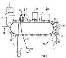
- FIG. 1 shows a transport cycle in the form of an intermittent cycle Transport chain (11) on which holders in the form of evenly spaced Cups (12) are mounted, which are used as temporary receptacles for portion containers, namely for initially open tubes (13), which contain boar sperm fluid are to be filled.
- the boar sperm was in a large container (14), for example holds one to several liters, delivered.
- the stations (18) to (21) are each in an even multiple of Distance between the cups (12) on the transport chain (11) from each other.
- the removal station (23) to the magazine station (18) empty the cups (12).
- the magazine station (18) becomes a portion container, namely an open plastic tube (13), in the intermittent movement of the at this station Entered conveyor chain (11) persistent cup (12).
- This mug arrives in the next steps to the filling station (19) with the example shown two filling heads (20), each of which has a bell (26) above the cup descends; of the filling heads (20) - in the embodiment shown common for both heads - via a first hose (27) a connection to the Large container (14) and a connection to a via a second hose (28) Vacuum source (29), that is, a suction pump or the like.
- a suction is drawn into the interior of the bell (26) respective filling head (20) of the filling station (19), and with the help of this suction a predetermined amount of sperm fluid is still in the tube (27) sucked in more detail from the large container (14) and through the open top of which is filled into the tube (13).
- the bells (26) pull then back and the transport chain (11) carries out the next step, in the case of two successive tubes, the first tube into the closing station (21) and the second tube in the area of the second filling head (20) device.
- the upper edge of the tube (13) is pressed together in the closing station (21) and welded together.
- Such tube welding devices are commercially available.
- the tube sealed in this way is the next step transported to the marking station (22), which is a labeling station or a Printing station can be, which is also a commercially available Device with a label feed or a print head.
- the bottling of boar sperm or other liquids that come to the respective filling stations can be metered in that a slight overpressure is applied to the large container and thereby the liquid is pressed into the portion container, or in that the large container over the portion container is positioned and the liquid in the portion container flows by gravity. It is also possible to pump the liquids through a peristaltic pump (Peristaltic pump) from the large container into the portion container.
- a peristaltic pump Peristaltic pump
- the closed and labeled or printed tube (13) now comes to Withdrawal station (23), where, for example, due to gravity, more complex Plant with the help of a pliers handle or according to the figures Blowing action leaves the relevant cup (12) and into a collecting container (33) is transported.
- a collecting container (33) there are several collection containers (33) available, each giving the tubes with sperm fluid a given Category, for example of a specific boar.
- the collection containers (33) sit articulated and by gravity in an upright position held along the circumference of a turntable (34) which is horizontal Axis (35) is rotatable. 1 is only the narrow edge the disc, which is circular in a plane perpendicular to the plane of the drawing is designed.
- a servomotor (36) serves to adjust the turntable (34).
- the entire system is controlled by a data processing device 37
- the arrangement has a total of one from DE-OS 38 20 387 or DE-GM 295 08 934 known structure.
- the stations (19) to (23) for the activity to be performed by them for an equal period of time, namely the Downtime of the transport chain (11) is available. Need individual Operations take a long time, so there are waiting times at the other stations. A longer time could be considered in particular at the filling station (19) because the filling process due to the flow properties and the resilience of the filling medium and not be accelerated arbitrarily by any foam formation can.
- the two are at the filling station (19) Filling heads (20) are present, each of which only half-fills the individual tube (13), namely the first filling head (20) with the first half portion and the second Filling head (20) with the second half portion.
- Fig. 2 shows in the course of the transport chain (11), the filling station (19) and Capping station (20) more in detail.
- Fig.n 2 and 3 show the bell (26) for each filler head (20), the vertical is movable and in the illustration of FIG. 3 on one of the cups (12) in the an open tube (13) is inserted, is attached.
- the bell (26) consists of a cylindrical housing (71) which is sealed at the top by a rubber stopper (72) is closed and along its lower edge an elastic sealing ring (73).
- a suction nipple (74) opens into the cylindrical housing (71) the hose (28) leading to the vacuum source (29) is connected.
- At the Bottom of the rubber stopper (72) protrudes a filling pipe (75) that over a Channel (76) in the rubber stopper with a connecting piece (77) for the hose (27) communicates, which leads to the large container (14).
- each filling head is so long that when it is on the upper edge of the cup (12) attached sealing ring (73) to the area of the bottom of the tube (13) enough.
- a filling nozzle (78) At the lower end of the filling pipe (75) there is a filling nozzle (78) with a check valve that closes the lower end of the tube when no negative pressure in the area in front of the pipe mouth relative to the pipe interior prevails.
- FIG. 2 there is another in front of the filling station (19)
- Control device in the form of a microswitch (81) which is dependent on it responds whether there is a tube (13) in the cup (12) or not. If there is no Tube (13) are the vertical movement of the bells (26) and the control of the Applying the vacuum so influenced that this application in this phase is omitted and the sperm liquid is not sucked directly into the cup (12) becomes.
- the non-response of the microswitch (81) causes the swiveling forward a drip catcher (82) arranged next to the transport chain (11), the during the locked seconds under the bottom of the fill pipe (75), which in turn is completed by the check valve of the filling nozzle (78) is.
- the trough (84) could also be suctioned off.
- Fig. 2 also shows the closing station (21) in which the tubes (13) through Ultrasonic welding can be closed. Between an anvil (88) and one Holding or pressing jaw (89) is the upper edge of the filled tube (13) first flattened and then using a sonotrode (90) in a manner known per se welded together.
- a sonotrode 90
- the removal station consists essentially of a blow nozzle (91), the blows an air blast into the cup (12) equipped with the tube (13), which leads to a Air accumulation and excess pressure build-up on the closed base of the cup (12), i.e. behind the tube (13). This pressure pad throws the tube (13) out of the cup (12) and into one of the collecting containers (33) which on the relevant position has been positioned.
- the marking station (22) does not necessarily have to be between the closing station (21) and the removal station (23) can be arranged, the labels also elsewhere, for example in the course of the removal at the magazine station (18), and it is also possible not to use the tubes to stick on printed labels, but to print directly, for example during transportation using an inkjet printer. These processes take only a short time, which allow a high clock frequency.
- the filling can also be distributed over three filling heads, which in the Step distance one behind the other at the filling station (19) and each Pour in a third of the portion amount. Finally, four or more Filling heads are used. With the ones following the first filling head Filling heads can the filling pipes (75) according to the tasks of the corresponding Filling head may also be shorter than the previous ones.
- the present description deals with the situation that individual tubes of To be transported station to station. With large systems, of course, too at the same time a large number of tubes are treated in parallel and in accordingly larger steps to be transported. According to the state of the art then, for example, five tubes at the same time through filling heads working in parallel filled, then through five parallel closing devices locked simultaneously, etc .; building on this example, then she sees Filling device according to the invention so that at the filling station ten or fifteen filling heads are active, the first five of which work simultaneously and in parallel the first portion, the next five simultaneously and in parallel the second portion etc. fill in five tubes each.
Landscapes
- Health & Medical Sciences (AREA)
- Engineering & Computer Science (AREA)
- Veterinary Medicine (AREA)
- Mechanical Engineering (AREA)
- Life Sciences & Earth Sciences (AREA)
- Wood Science & Technology (AREA)
- Reproductive Health (AREA)
- Zoology (AREA)
- Animal Behavior & Ethology (AREA)
- General Health & Medical Sciences (AREA)
- Public Health (AREA)
- Catching Or Destruction (AREA)
- Basic Packing Technique (AREA)
Abstract
Description
- Fig. 1
- eine schematische Vorderansicht einer Erfindungsgemäßen Abfüllvorrichtung;
- Fig. 2
- eine schematische Darstellung von auf eine Magazin-Station folgenden Stationen, nämlich einer Einfüll-Station und einer Verschließ-Station;
- Fig. 3
- einen Querschnitt durch einen Becher mit einer eingesetzten Tube in der Einfüll-Station nach Fig. 2.
Claims (10)
- Abfüllvorrichtung zum Abfüllen von in Großbehältern (14) angelieferter Flüssigkeit von Ebersperma in Portionsbehälter (13), mit einer Transportstrecke (11) entlang Bearbeitungs-Stationen (18 - 23), die Halter (12) zur Aufnahme der Portionsbehälter (13) mit sich führt und zum Transport der Halter (12) in konstanten Schrittweiten entlang den Stationen mit kurzem Stillstand an den Stationen antreibbar ist, nämlich einer Magazin-Station (18), einer Einfüll-Station (19), einer Verschließ-Station (21) und einer Entnahme-Station (23), die hintereinander entlang der Bahn der Transportstrecke (11) angeordnet sind, wobei an der Einfüll-Station (19) wenigstens eine an den einzelnen Halter (12) heranführbare Einfülldüse (78) angeordnet ist, die über eine Leitung (27) mit dem Großbehälter (14) verbindbar ist, dadurch gekennzeichnet, daß in der Einfüll-Station (19) mehrere in Schrittweite hintereinander entlang der Transportstrecke angeordnete Einfülldüsen (78) vorhanden sind.
- Abfüllvorrichtung nach Anspruch 1, dadurch gekennzeichnet, daß die Einfülldüsen (78) über jeweils eigene Ansteuerungen verfügen.
- Abfüllvorrichtung nach Anspruch 1 oder 2, dadurch gekennzeichnet, daß die Einfülldüsen (78) zumindest gruppenweise eigene Leitungen zum Großbehälter (14) bzw. zu sonstigen Behältern aufweisen.
- Abfüllvorrichtung nach einem der Ansprüche 1 bis 3, dadurch gekennzeichnet, daß, bezogen auf die systemgebundene Abfülldauer eines Portionsbehälters (13), die Stillstandszeit an den Einfülldüsen (78) der Einfüllstation (19) auf eine Dauer gesteuert ist, die der Abfülldauer geteilt durch die Zahl der hintereinander angeordneten Einfülldüsen gleich oder geringfügig länger als sie ist.
- Abfüllvorrichtung nach einem der Ansprüche 1 bis 4, dadurch gekennzeichnet, daß als eine der Bearbeitungsstationen, entlang denen die Transportstrecke (11) verläuft, auch eine Markier-Station (22) vorhanden ist.
- Abfüllvorrichtung nach einem der Ansprüche 1 bis 5, dadurch gekennzeichnet, daß die Transportstrecke eine Strecke eines Transportumlaufs ist.
- Verfahren zum Betrieb der Abfüllvorrichtung nach einem der Ansprüche 1 bis 5, mit einer gegebenen systemgebundenen Mindest-Abfülldauer des einzelnen Portionsbehälters (13) bis zu seinem End-Füllungsmaß der Spermaflüssigkeit im Behälter, dadurch gekennzeichnet, daß man für die sich intermittierend mit jeweiligen Stillstandszeiten bewegende Transportstrecke (11) vorzgsweise konstante Stillstandszeiten wählt, die einen Teil der systemgebundenen Mindest-Abfülldauer der Portionsbehälter (13) betragen, und die einzelnen Portionsbehälter schrittweise in Teilmengen über eine Mehrzahl von Stillstandszeiten hinweg bis zum End-Füllungsmaß abfüllt.
- Verfahren nach Anspruch 7, dadurch gekennzeichnet, daß man parallel jeweils eine Mehrzahl von Portionsbehältern (13) mit je Stillstandszeit einer jeweiligen Teilmenge abfüllt.
- Verfahren nach Anspruch 7 oder 8, dadurch gekennzeichnet, daß man außer der Spermaflüssigkeit während wenigstens einer der Stillstandszeiten in den oder die Portionsbehälter (13) auch Zusatzsubstanzen füllt.
- Verfahren nach Anspruch 9, dadurch gekennzeichnet, daß man zwischen zwei Abfüllschritten unterschiedlicher Substanzen im Portionsbehälter eine die abgefüllten Substanzen separierende Sperre bildet.
Applications Claiming Priority (2)
| Application Number | Priority Date | Filing Date | Title |
|---|---|---|---|
| DE20012775U | 2000-07-21 | ||
| DE20012775U DE20012775U1 (de) | 2000-07-21 | 2000-07-21 | Abfüllvorrichtung zum Abfüllen von Ebersperma |
Publications (2)
| Publication Number | Publication Date |
|---|---|
| EP1174096A2 true EP1174096A2 (de) | 2002-01-23 |
| EP1174096A3 EP1174096A3 (de) | 2003-01-29 |
Family
ID=7944330
Family Applications (1)
| Application Number | Title | Priority Date | Filing Date |
|---|---|---|---|
| EP01117582A Withdrawn EP1174096A3 (de) | 2000-07-21 | 2001-07-20 | Abfüllvorrichtung zum Abfüllen von Ebersperma und Verfahren zu ihrem Betrieb |
Country Status (2)
| Country | Link |
|---|---|
| EP (1) | EP1174096A3 (de) |
| DE (1) | DE20012775U1 (de) |
Cited By (1)
| Publication number | Priority date | Publication date | Assignee | Title |
|---|---|---|---|---|
| WO2009068227A1 (de) * | 2007-11-26 | 2009-06-04 | Minitüb Abfüll- und Labortechnik GmbH & Co. KG | Vorrichtung zum verschliessen von kunststoffbehältern |
Families Citing this family (2)
| Publication number | Priority date | Publication date | Assignee | Title |
|---|---|---|---|---|
| DE102007037094A1 (de) * | 2007-08-07 | 2009-02-12 | Iwk Verpackungstechnik Gmbh | Verfahren und Vorrichtung zur Aufbringung eines Etiketts auf die Außenoberfläche einer Tube |
| DE102009040496A1 (de) * | 2009-09-08 | 2011-03-10 | Iwk Verpackungstechnik Gmbh | Tubenfüllmaschine und Verfahren zur Steuerung einer Dosierpumpe insbesondere in einer Tubenfüllmaschine |
Citations (3)
| Publication number | Priority date | Publication date | Assignee | Title |
|---|---|---|---|---|
| DE3820387A1 (de) | 1988-06-15 | 1989-12-21 | Simmet Ludwig Dr Med Vet | Abfuellvorrichtung zum abfuellen von spermafluessigkeit |
| DE9017280U1 (de) | 1990-12-21 | 1991-03-14 | Simmet, Ludwig, Dr.med.vet., 84036 Landshut | Abfüllvorrichtung zum Abfüllen von Spermaflüssigkeit |
| DE29508934U1 (de) | 1995-06-08 | 1995-08-17 | Simmet, Ludwig, Dr.med.vet., 84036 Landshut | Abfüllvorrichtung zum Abfüllen von Spermaflüssigkeit |
-
2000
- 2000-07-21 DE DE20012775U patent/DE20012775U1/de not_active Expired - Lifetime
-
2001
- 2001-07-20 EP EP01117582A patent/EP1174096A3/de not_active Withdrawn
Patent Citations (3)
| Publication number | Priority date | Publication date | Assignee | Title |
|---|---|---|---|---|
| DE3820387A1 (de) | 1988-06-15 | 1989-12-21 | Simmet Ludwig Dr Med Vet | Abfuellvorrichtung zum abfuellen von spermafluessigkeit |
| DE9017280U1 (de) | 1990-12-21 | 1991-03-14 | Simmet, Ludwig, Dr.med.vet., 84036 Landshut | Abfüllvorrichtung zum Abfüllen von Spermaflüssigkeit |
| DE29508934U1 (de) | 1995-06-08 | 1995-08-17 | Simmet, Ludwig, Dr.med.vet., 84036 Landshut | Abfüllvorrichtung zum Abfüllen von Spermaflüssigkeit |
Cited By (1)
| Publication number | Priority date | Publication date | Assignee | Title |
|---|---|---|---|---|
| WO2009068227A1 (de) * | 2007-11-26 | 2009-06-04 | Minitüb Abfüll- und Labortechnik GmbH & Co. KG | Vorrichtung zum verschliessen von kunststoffbehältern |
Also Published As
| Publication number | Publication date |
|---|---|
| DE20012775U1 (de) | 2000-12-07 |
| EP1174096A3 (de) | 2003-01-29 |
Similar Documents
| Publication | Publication Date | Title |
|---|---|---|
| DE69606453T2 (de) | Uebergabeeinrichtung für Kontaktlinsen | |
| DE69605970T2 (de) | Verfahren und Vorrichtung zum Transportieren, Inspizieren und Verpacken von Kontaktlinsen nach der Hydration | |
| EP0993418A1 (de) | Verfahren und anlage zum verschliessen von flaschen mit sterilen verschlusskappen | |
| DE10127896B4 (de) | Übergabevorrichtung und -verfahren für Folienbeutel | |
| EP0638478B1 (de) | Vorrichtung zum Entnehmen von Gefässen aus Transportbehältern | |
| DE2916338A1 (de) | Vorrichtung zum foerdern und ausrichten von flaschenaehnlichen behaeltern | |
| EP3909872B1 (de) | Verfahren zum übergeben von produkten | |
| DE102018212254A1 (de) | Handhabungs- und/oder Verpackungsvorrichtung und Verfahren zum Verpacken von Artikeln | |
| WO2000068079A1 (de) | Vorrichtung zum verschliessen von kunststoffflaschen | |
| DE2903468A1 (de) | Vorrichtung und verfahren zum pruefen von flaschenverschluessen | |
| EP1584559B1 (de) | Verfahren und Vorrichtung zum Ausrichten von Gefässen für flüssige und fliessfähige Medien, insbesondere Getränke | |
| EP1174096A2 (de) | Abfüllvorrichtung zum Abfüllen von Ebersperma und Verfahren zu ihrem Betrieb | |
| EP2711314B1 (de) | Verfahren und Vorrichtung zum Transportieren von mit Flüssigkeit gefüllten Behältern | |
| DE2020470C3 (de) | Vorrichtung zum reihenweisen Einbringen von Gefäßen in Packbehälter | |
| DE60201808T2 (de) | Vorrichtung zum Verschliessen von Flaschen mit Korken | |
| DE3820387A1 (de) | Abfuellvorrichtung zum abfuellen von spermafluessigkeit | |
| EP2054861A1 (de) | Aufstellvorrichtung für leergutbehälter | |
| DE10341451A1 (de) | Verfahren und Vorrichtung zum Handhaben von Blisterstreifen | |
| DE2719957C3 (de) | Etikettiervorrichtung | |
| DE29508934U1 (de) | Abfüllvorrichtung zum Abfüllen von Spermaflüssigkeit | |
| EP1231167B1 (de) | Abfüllmaschine mit einer Vereinzelungsvorrichtung und einer Transportvorrichtung | |
| DE69524237T2 (de) | Verpackungsmaschine | |
| DE9017280U1 (de) | Abfüllvorrichtung zum Abfüllen von Spermaflüssigkeit | |
| DE2435671C3 (de) | Verfahren und Vorrichtung zum Handhaben und Lagern von länglichen Gegenständen | |
| EP3838839A1 (de) | Vorrichtung und verfahren zum befüllen eines behälters mit einem füllprodukt |
Legal Events
| Date | Code | Title | Description |
|---|---|---|---|
| PUAI | Public reference made under article 153(3) epc to a published international application that has entered the european phase |
Free format text: ORIGINAL CODE: 0009012 |
|
| AK | Designated contracting states |
Kind code of ref document: A2 Designated state(s): AT BE CH CY DE DK ES FI FR GB GR IE IT LI LU MC NL PT SE TR |
|
| AX | Request for extension of the european patent |
Free format text: AL;LT;LV;MK;RO;SI |
|
| PUAL | Search report despatched |
Free format text: ORIGINAL CODE: 0009013 |
|
| AK | Designated contracting states |
Designated state(s): AT BE CH CY DE DK ES FI FR GB GR IE IT LI LU MC NL PT SE TR |
|
| AX | Request for extension of the european patent |
Extension state: AL LT LV MK RO SI |
|
| 17P | Request for examination filed |
Effective date: 20030515 |
|
| AKX | Designation fees paid |
Designated state(s): AT BE CH CY DE DK ES FI FR GB GR IE IT LI LU MC NL PT SE TR |
|
| 17Q | First examination report despatched |
Effective date: 20080304 |
|
| STAA | Information on the status of an ep patent application or granted ep patent |
Free format text: STATUS: THE APPLICATION IS DEEMED TO BE WITHDRAWN |
|
| 18D | Application deemed to be withdrawn |
Effective date: 20080916 |