EP1174097B1 - Vorrichtung zum Verschliessen einer Verbindung zwischen der Aorta und der Arteria pulmonalis - Google Patents
Vorrichtung zum Verschliessen einer Verbindung zwischen der Aorta und der Arteria pulmonalis Download PDFInfo
- Publication number
- EP1174097B1 EP1174097B1 EP01114920A EP01114920A EP1174097B1 EP 1174097 B1 EP1174097 B1 EP 1174097B1 EP 01114920 A EP01114920 A EP 01114920A EP 01114920 A EP01114920 A EP 01114920A EP 1174097 B1 EP1174097 B1 EP 1174097B1
- Authority
- EP
- European Patent Office
- Prior art keywords
- closures
- closure
- tensioning element
- umbrella
- aorta
- Prior art date
- Legal status (The legal status is an assumption and is not a legal conclusion. Google has not performed a legal analysis and makes no representation as to the accuracy of the status listed.)
- Expired - Lifetime
Links
- 210000000709 aorta Anatomy 0.000 title claims abstract description 20
- 230000003014 reinforcing effect Effects 0.000 claims abstract 2
- 210000001147 pulmonary artery Anatomy 0.000 claims description 19
- 239000000463 material Substances 0.000 claims description 10
- 238000003780 insertion Methods 0.000 claims description 9
- 230000037431 insertion Effects 0.000 claims description 9
- 230000002787 reinforcement Effects 0.000 claims description 8
- 239000002184 metal Substances 0.000 claims description 6
- 239000002210 silicon-based material Substances 0.000 claims 1
- 229940125782 compound 2 Drugs 0.000 description 7
- 210000004204 blood vessel Anatomy 0.000 description 4
- 229920001296 polysiloxane Polymers 0.000 description 4
- 238000002604 ultrasonography Methods 0.000 description 3
- 206010020751 Hypersensitivity Diseases 0.000 description 2
- 230000006978 adaptation Effects 0.000 description 2
- 208000026935 allergic disease Diseases 0.000 description 2
- 238000010276 construction Methods 0.000 description 2
- 239000007788 liquid Substances 0.000 description 2
- 230000002093 peripheral effect Effects 0.000 description 2
- 238000001356 surgical procedure Methods 0.000 description 2
- 210000001367 artery Anatomy 0.000 description 1
- 239000008280 blood Substances 0.000 description 1
- 210000004369 blood Anatomy 0.000 description 1
- 230000017531 blood circulation Effects 0.000 description 1
- 150000001875 compounds Chemical class 0.000 description 1
- 238000004519 manufacturing process Methods 0.000 description 1
- 230000001681 protective effect Effects 0.000 description 1
- 230000002685 pulmonary effect Effects 0.000 description 1
- 238000007789 sealing Methods 0.000 description 1
Images



Classifications
-
- A—HUMAN NECESSITIES
- A61—MEDICAL OR VETERINARY SCIENCE; HYGIENE
- A61B—DIAGNOSIS; SURGERY; IDENTIFICATION
- A61B17/00—Surgical instruments, devices or methods
- A61B17/12—Surgical instruments, devices or methods for ligaturing or otherwise compressing tubular parts of the body, e.g. blood vessels or umbilical cord
- A61B17/12022—Occluding by internal devices, e.g. balloons or releasable wires
- A61B17/12131—Occluding by internal devices, e.g. balloons or releasable wires characterised by the type of occluding device
-
- A—HUMAN NECESSITIES
- A61—MEDICAL OR VETERINARY SCIENCE; HYGIENE
- A61B—DIAGNOSIS; SURGERY; IDENTIFICATION
- A61B17/00—Surgical instruments, devices or methods
- A61B17/12—Surgical instruments, devices or methods for ligaturing or otherwise compressing tubular parts of the body, e.g. blood vessels or umbilical cord
- A61B17/12022—Occluding by internal devices, e.g. balloons or releasable wires
-
- A—HUMAN NECESSITIES
- A61—MEDICAL OR VETERINARY SCIENCE; HYGIENE
- A61B—DIAGNOSIS; SURGERY; IDENTIFICATION
- A61B17/00—Surgical instruments, devices or methods
- A61B17/12—Surgical instruments, devices or methods for ligaturing or otherwise compressing tubular parts of the body, e.g. blood vessels or umbilical cord
- A61B17/12022—Occluding by internal devices, e.g. balloons or releasable wires
- A61B17/12099—Occluding by internal devices, e.g. balloons or releasable wires characterised by the location of the occluder
- A61B17/12109—Occluding by internal devices, e.g. balloons or releasable wires characterised by the location of the occluder in a blood vessel
-
- A—HUMAN NECESSITIES
- A61—MEDICAL OR VETERINARY SCIENCE; HYGIENE
- A61B—DIAGNOSIS; SURGERY; IDENTIFICATION
- A61B17/00—Surgical instruments, devices or methods
- A61B17/12—Surgical instruments, devices or methods for ligaturing or otherwise compressing tubular parts of the body, e.g. blood vessels or umbilical cord
- A61B17/12022—Occluding by internal devices, e.g. balloons or releasable wires
- A61B17/12131—Occluding by internal devices, e.g. balloons or releasable wires characterised by the type of occluding device
- A61B17/12168—Occluding by internal devices, e.g. balloons or releasable wires characterised by the type of occluding device having a mesh structure
- A61B17/12172—Occluding by internal devices, e.g. balloons or releasable wires characterised by the type of occluding device having a mesh structure having a pre-set deployed three-dimensional shape
-
- A—HUMAN NECESSITIES
- A61—MEDICAL OR VETERINARY SCIENCE; HYGIENE
- A61F—FILTERS IMPLANTABLE INTO BLOOD VESSELS; PROSTHESES; DEVICES PROVIDING PATENCY TO, OR PREVENTING COLLAPSING OF, TUBULAR STRUCTURES OF THE BODY, e.g. STENTS; ORTHOPAEDIC, NURSING OR CONTRACEPTIVE DEVICES; FOMENTATION; TREATMENT OR PROTECTION OF EYES OR EARS; BANDAGES, DRESSINGS OR ABSORBENT PADS; FIRST-AID KITS
- A61F2/00—Filters implantable into blood vessels; Prostheses, i.e. artificial substitutes or replacements for parts of the body; Appliances for connecting them with the body; Devices providing patency to, or preventing collapsing of, tubular structures of the body, e.g. stents
- A61F2/02—Prostheses implantable into the body
- A61F2/04—Hollow or tubular parts of organs, e.g. bladders, tracheae, bronchi or bile ducts
- A61F2/06—Blood vessels
-
- A—HUMAN NECESSITIES
- A61—MEDICAL OR VETERINARY SCIENCE; HYGIENE
- A61F—FILTERS IMPLANTABLE INTO BLOOD VESSELS; PROSTHESES; DEVICES PROVIDING PATENCY TO, OR PREVENTING COLLAPSING OF, TUBULAR STRUCTURES OF THE BODY, e.g. STENTS; ORTHOPAEDIC, NURSING OR CONTRACEPTIVE DEVICES; FOMENTATION; TREATMENT OR PROTECTION OF EYES OR EARS; BANDAGES, DRESSINGS OR ABSORBENT PADS; FIRST-AID KITS
- A61F2/00—Filters implantable into blood vessels; Prostheses, i.e. artificial substitutes or replacements for parts of the body; Appliances for connecting them with the body; Devices providing patency to, or preventing collapsing of, tubular structures of the body, e.g. stents
- A61F2/01—Filters implantable into blood vessels
- A61F2002/016—Filters implantable into blood vessels made from wire-like elements
-
- A—HUMAN NECESSITIES
- A61—MEDICAL OR VETERINARY SCIENCE; HYGIENE
- A61F—FILTERS IMPLANTABLE INTO BLOOD VESSELS; PROSTHESES; DEVICES PROVIDING PATENCY TO, OR PREVENTING COLLAPSING OF, TUBULAR STRUCTURES OF THE BODY, e.g. STENTS; ORTHOPAEDIC, NURSING OR CONTRACEPTIVE DEVICES; FOMENTATION; TREATMENT OR PROTECTION OF EYES OR EARS; BANDAGES, DRESSINGS OR ABSORBENT PADS; FIRST-AID KITS
- A61F2230/00—Geometry of prostheses classified in groups A61F2/00 - A61F2/26 or A61F2/82 or A61F9/00 or A61F11/00 or subgroups thereof
- A61F2230/0002—Two-dimensional shapes, e.g. cross-sections
- A61F2230/0004—Rounded shapes, e.g. with rounded corners
- A61F2230/0006—Rounded shapes, e.g. with rounded corners circular
-
- A—HUMAN NECESSITIES
- A61—MEDICAL OR VETERINARY SCIENCE; HYGIENE
- A61F—FILTERS IMPLANTABLE INTO BLOOD VESSELS; PROSTHESES; DEVICES PROVIDING PATENCY TO, OR PREVENTING COLLAPSING OF, TUBULAR STRUCTURES OF THE BODY, e.g. STENTS; ORTHOPAEDIC, NURSING OR CONTRACEPTIVE DEVICES; FOMENTATION; TREATMENT OR PROTECTION OF EYES OR EARS; BANDAGES, DRESSINGS OR ABSORBENT PADS; FIRST-AID KITS
- A61F2230/00—Geometry of prostheses classified in groups A61F2/00 - A61F2/26 or A61F2/82 or A61F9/00 or A61F11/00 or subgroups thereof
- A61F2230/0002—Two-dimensional shapes, e.g. cross-sections
- A61F2230/0004—Rounded shapes, e.g. with rounded corners
- A61F2230/0008—Rounded shapes, e.g. with rounded corners elliptical or oval
-
- A—HUMAN NECESSITIES
- A61—MEDICAL OR VETERINARY SCIENCE; HYGIENE
- A61F—FILTERS IMPLANTABLE INTO BLOOD VESSELS; PROSTHESES; DEVICES PROVIDING PATENCY TO, OR PREVENTING COLLAPSING OF, TUBULAR STRUCTURES OF THE BODY, e.g. STENTS; ORTHOPAEDIC, NURSING OR CONTRACEPTIVE DEVICES; FOMENTATION; TREATMENT OR PROTECTION OF EYES OR EARS; BANDAGES, DRESSINGS OR ABSORBENT PADS; FIRST-AID KITS
- A61F2230/00—Geometry of prostheses classified in groups A61F2/00 - A61F2/26 or A61F2/82 or A61F9/00 or A61F11/00 or subgroups thereof
- A61F2230/0002—Two-dimensional shapes, e.g. cross-sections
- A61F2230/0017—Angular shapes
- A61F2230/0019—Angular shapes rectangular
-
- A—HUMAN NECESSITIES
- A61—MEDICAL OR VETERINARY SCIENCE; HYGIENE
- A61F—FILTERS IMPLANTABLE INTO BLOOD VESSELS; PROSTHESES; DEVICES PROVIDING PATENCY TO, OR PREVENTING COLLAPSING OF, TUBULAR STRUCTURES OF THE BODY, e.g. STENTS; ORTHOPAEDIC, NURSING OR CONTRACEPTIVE DEVICES; FOMENTATION; TREATMENT OR PROTECTION OF EYES OR EARS; BANDAGES, DRESSINGS OR ABSORBENT PADS; FIRST-AID KITS
- A61F2230/00—Geometry of prostheses classified in groups A61F2/00 - A61F2/26 or A61F2/82 or A61F9/00 or A61F11/00 or subgroups thereof
- A61F2230/0002—Two-dimensional shapes, e.g. cross-sections
- A61F2230/0028—Shapes in the form of latin or greek characters
- A61F2230/005—Rosette-shaped, e.g. star-shaped
-
- A—HUMAN NECESSITIES
- A61—MEDICAL OR VETERINARY SCIENCE; HYGIENE
- A61F—FILTERS IMPLANTABLE INTO BLOOD VESSELS; PROSTHESES; DEVICES PROVIDING PATENCY TO, OR PREVENTING COLLAPSING OF, TUBULAR STRUCTURES OF THE BODY, e.g. STENTS; ORTHOPAEDIC, NURSING OR CONTRACEPTIVE DEVICES; FOMENTATION; TREATMENT OR PROTECTION OF EYES OR EARS; BANDAGES, DRESSINGS OR ABSORBENT PADS; FIRST-AID KITS
- A61F2230/00—Geometry of prostheses classified in groups A61F2/00 - A61F2/26 or A61F2/82 or A61F9/00 or A61F11/00 or subgroups thereof
- A61F2230/0063—Three-dimensional shapes
- A61F2230/0067—Three-dimensional shapes conical
-
- A—HUMAN NECESSITIES
- A61—MEDICAL OR VETERINARY SCIENCE; HYGIENE
- A61F—FILTERS IMPLANTABLE INTO BLOOD VESSELS; PROSTHESES; DEVICES PROVIDING PATENCY TO, OR PREVENTING COLLAPSING OF, TUBULAR STRUCTURES OF THE BODY, e.g. STENTS; ORTHOPAEDIC, NURSING OR CONTRACEPTIVE DEVICES; FOMENTATION; TREATMENT OR PROTECTION OF EYES OR EARS; BANDAGES, DRESSINGS OR ABSORBENT PADS; FIRST-AID KITS
- A61F2230/00—Geometry of prostheses classified in groups A61F2/00 - A61F2/26 or A61F2/82 or A61F9/00 or A61F11/00 or subgroups thereof
- A61F2230/0063—Three-dimensional shapes
- A61F2230/0086—Pyramidal, tetrahedral, or wedge-shaped
-
- A—HUMAN NECESSITIES
- A61—MEDICAL OR VETERINARY SCIENCE; HYGIENE
- A61F—FILTERS IMPLANTABLE INTO BLOOD VESSELS; PROSTHESES; DEVICES PROVIDING PATENCY TO, OR PREVENTING COLLAPSING OF, TUBULAR STRUCTURES OF THE BODY, e.g. STENTS; ORTHOPAEDIC, NURSING OR CONTRACEPTIVE DEVICES; FOMENTATION; TREATMENT OR PROTECTION OF EYES OR EARS; BANDAGES, DRESSINGS OR ABSORBENT PADS; FIRST-AID KITS
- A61F2230/00—Geometry of prostheses classified in groups A61F2/00 - A61F2/26 or A61F2/82 or A61F9/00 or A61F11/00 or subgroups thereof
- A61F2230/0063—Three-dimensional shapes
- A61F2230/0093—Umbrella-shaped, e.g. mushroom-shaped
Definitions
- the invention relates to a device for closing an open connection between the aorta and the pulmonary artery (pulmonary artery) with a closure element which can be inserted into this connection by means of a catheter, the closure element having two spaced closures which are elastically connected via a tension element and which are in Use position cover or fill the two mouths of the connection between the aorta and the pulmonary artery.
- the device according to the preamble of claim 1 is known from the patent DD233303.
- the device is essentially formed by a insertable by means of a catheter closure element with two spaced closures of the type mentioned above, which is characterized in that a closure and the tension element is a continuous, to the vicinity of the other closure reaching inner longitudinal cavity for the entry of a stylet or the like sliding and / or turning tool which is stiffened and / or reinforced at its end, and that in the region of the entry into the inner longitudinal cavity of the tension element, a reinforcement is arranged, on which one over the immediate adjacent closure outwardly projecting eyelet and a hinged to this drawstring are arranged.
- a corresponding closure element can be brought into the opening, where it is closed regardless of their length on both sides.
- the arranged between the two closures elastic tension element allows an adaptation to differences in length of the corresponding opening.
- both closures are pressed by this elastic tension element to their "seat” and give a good seal. So it can be a good adaptation both to the length as well as to the diameter of the opening can be achieved and a residual flow between the aorta and the pulmonary artery (pulmonary artery) is avoided.
- the reinforced inner longitudinal cavity allows the use of a stylet or similar tool during insertion.
- the pull thread located at the eyelet on the proximal closure or "umbrella” may be considered a "safety line". Only when it is checked after insertion of the closure element that the closures of the closure element are placed correctly, this thread can be removed by pulling on one end. Otherwise, the entire closure may be removed by pulling on both ends of this eyelet-guided thread and the catheter. Also, by alternately operating the drawstring and the stylet or tool the best possible placement can be sought and achieved.
- the closure element can thus be inserted from one side into the opening to be closed and placed so that the one closure reaches the end of the opening or the mouth of this opening and closes it in the insertion direction.
- the second closure then covers the inlet opening and the insertion tool can be withdrawn again.
- the reinforcement in the region of the entry into the inner longitudinal cavity of the tension element is a helix preferably made of metal wire.
- the reinforcement in the region of the entry into the inner longitudinal cavity of the tension element is a helix preferably made of metal wire.
- closures and the tension element (s) connecting them consist of elastic plastic, in particular of silicone material.
- Silicone has been proven for many years, for example, in implantable pacemaker electrodes as allergy-free and biocompatible. At the same time it is rubber-elastic and therefore can adjust the closures themselves and the one or more tension elements automatically to anatomical conditions.
- the two closures and the elastically connecting tension element can be integrally connected. Accordingly easy is the introduction and placement of this closure element.
- the two closures of the closure element can be plate-shaped or umbrella-like and can be recessed approximately evenly or at least partially concave on its outer surface. This avoids constriction of the aortic and pulmonary artery in relation to convex occlusions.
- the inner longitudinal cavity of the tension element in particular by a helix, for example of metal wire, is reinforced on the inside and that the reinforcement at its end forms an inner hollow profiling or delimits, for example, a slot in which flat end of the stylet or tool fits.
- the user can advance the closure element by means of the stylet or tool and optionally also twist something until the closures have reached their intended position at the two mutually remote mouths of the opening and close them securely.
- the umbrella-type closures can be foldable against the elasticity of their material or material and can be inserted into a tube-like delivery catheter, which can be part of the device, the inner cross-section of which corresponds to the outer dimension of the folded closures.
- the entire closure element can be placed with both closures first in a folded arrangement within the catheter in the region of the opening and then inserted there with the help of a also advanceable through the catheter stylet or tool from the delivery catheter out into the opening.
- the umbrella-like closures can be a round or about have quadrangular or oval peripheral contour and their surface may in particular stiffening ribs and / or webs have. Thus, adjustments to different anatomical conditions in the area of the opening to be fired are possible.
- a further embodiment of the invention for increasing the security of the seal of the opening to be closed can consist in that the tension element carries at least one further elastic closure between the two end closures, which is elastically adaptable at least in its edge region. This further closure can then rest against the inner wall between the two end-side closures in the course of the approximately channel-shaped opening to be closed, and thus further prevent unwanted blood flow through this opening.
- two spaced apart further closures can be arranged on the tension element between the two end closures whose outer diameter is in particular smaller than that of the end-side closures, so that they fit into the interior of the channel-shaped opening.
- the one or more additional closures in the course of the tension element may also have an umbrella shape and against a restoring force of the material foldable, umbrella-like or conical shape. Thus, they can also be accommodated within the delivery catheter.
- Which closure shape and size is selected may optionally be determined prior to surgery, for example by ultrasound. Also, the umbrella-like closures can be cut after determining the size of the opening to be closed or the "duct", which could be carried out especially with a production of silicone with a simple pair of scissors on the operating table.
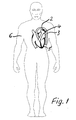
- FIG. 3 A designated throughout with 1, especially good in Fig. 3 recognizable device is used to close one after birth open connection 2 between the aorta 3 and the pulmonary artery or pulmonary artery 4, where this compound 2 in Fig. 1 and 2 at the heart 5 of a person 6 can be seen schematized.
- the device 1 is essentially formed by a catheter 7 insertable closure element 8, so that a surgical procedure for closing the connection 2 can be avoided.
- catheter 7 while only the end in Fig. 3 is indicated, but this end is designed so that it can accommodate the entire closure element 8 in order to be brought by blood vessels to the site can.
- Fig. 2 In Fig. 2 and especially in Fig. 3 it is shown that the closure element 8 has two spaced, connected via an elastic tension element 9, but spaced closures 10 and 11, which in the position of use, the two mouths of the between the aorta 3 and the artery Cover or fill in pulmonary lane 2.
- Fig. 3 indicates that these mouths of the compound 2 are optionally slightly extended compared to the rest of this channel-like compound 2, but nevertheless covered by the closures 10 and 11, so that a liquid passage is prevented.
- FIG. 2 schematically indicates that the two closures 10 and 11 could be connected by a spring as a tension element 9, it is provided according to FIG. 3, that the closures 10 and 11 and the tension element 9 connecting them made of elastic plastic, preferably made of silicone Material which has proved to be inert and allergy-free when used within the human body.
- the two closures 10 and 11 and the elastically connecting tension element 9 are integrally connected in the embodiment.
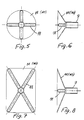
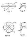
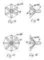
- the two closures 10 and 11, each about may have the same shape and the same structure and of which different examples are shown in Figures 5 to 18 in terms of shape and construction, are each about umbrella-like, that is, they can with respect to the shapes shown and also with respect to the arrangement in FIG. 3 are folded to a considerably smaller cross-section, so that they fit into the catheter 7. In the position of use they are flat or, as shown in the embodiments, concavely sunk on its outer surface, so that on both blood vessels 3 and 4 no projection through these closures 10 and 11 is formed.
- the one closure 11, namely the proximal closure 11 and the tension member 9 has a continuous, reaching into the vicinity of the other closure 10 inner longitudinal cavity 12 for the entry of a stylet or the like sliding and / or turning tool , which is stiffened and armored at least at the end in the area of the detail A (see also FIG.
- a stylet or the like sliding and / or turning tool which is stiffened and armored at least at the end in the area of the detail A (see also FIG.
- the closure 10 thus differs from the closure 11 in that it has no such inlet opening for such a tool.
- the inner longitudinal cavity 12 of the tension element 9 is reinforced by a helix 13, for example from a metal wire inside and this reinforcement forms at its end near the closure 10 an inside hollow profiling, which additionally contains a slot 14 in FIG correspondingly flat end of the stylet or tool fits, so that rotational movements to adapt the closure 10 or the entire closure element 8 to certain anatomical conditions are possible.
- the umbrella-like closures 10 and 11 are against the elasticity of their material or material in a manner not shown, as already mentioned, foldable and insertable into the tube-like Zutechnologykatheter 7 before the closure element 8 is brought to its place of use.
- the inner cross section of this delivery catheter 7 thus corresponds to the outer dimensions of the folded closures 10 and 11.
- Fig. 3 can be seen further in the region of the entry into the inner longitudinal cavity 12 of the tension element 9, so close to the closure 11, a reinforcement in the form of a second coil 15, for example made of metal wire.
- the tension element 9 is stabilized in particular near both closures 10 and 11.
- this drawstring 17 With the help of this drawstring 17, the entire closure element 8 can be pulled out of the compound 2 by a tensile force at its two ends, for example, if a check with ultrasound shows that the placement is not correct or the tightness was not achieved with the necessary security or Closures 10 and 11 do not fit exactly enough.
- the drawstring 17 can be removed at one end from the eyelet 16.
- the rigidity and adaptability of the closures 10 and 11 can be predetermined or chosen differently depending on the application and anatomical conditions.
- the peripheral contours can also be circumcised by the surgeon, especially in the located between the stiffening ribs or webs 18 edge regions.
- their outer diameter in the embodiment are smaller than that of the end-side closures 10 and 11 in order to take into account the generally smaller cross-section in the interior of the connection 2 relative to the ends or mouths of this connection 2. It is particularly well illustrated by Fig. 3 that in this way a passage of liquid from one blood vessel to the other is largely excluded.
- the additional closures 19 are conical as shown in FIG. 3 and could also be foldable umbrella-like and against a restoring force of the material in order to better adapt to different inner contours within the compound 2.
- a suitable closure element 8 can be selected and introduced by means of the catheter 7.
- the circumferential contour of the closures 10 and 11 can be previously cut to size on the operating table.
- the device 1 is folded in the protective or insertion catheter 7 housed and is pushed to the desired location and pushed out there with a stylet or pushing tool.
- the flattened end of this tool fits into the distal receiving slot 14 at the end of the inner longitudinal cavity 12 of the tension member 9, so that the distal closure 10 can also be rotated to the "correct" position if necessary.
- the umbrella-like closures 10 and 11 at both ends of the closure element 8 ensure a secure and tight fixation even with large anatomical anomalies.
- the device 1 is used for closing a left after the birth of a person 6 channel-like connection 2 between the aorta 3 and the pulmonary artery 4. It is essentially formed by a catheter 7 insertable closure element 8, which two spaced and an elastic tension element 9 connected closures 10 and 11, which in turn have a certain elasticity and cover in the position of use, the two mouths or ends of the located between the aorta 3 and the pulmonary artery 4 compound 2 or fill, it is expedient if these closures 10 and 11 are foldable so that they fit on the one hand in the catheter 7 and on the other hand can be inserted through the connection 2 and brought to the respective application site. With an arranged in the region of the entry into the inner longitudinal cavity 12 eyelet 16 and this passing through the drawstring 17, the seat the closure element can be corrected especially by alternating operation of the thread 17 and the stylet or tool.
Landscapes
- Health & Medical Sciences (AREA)
- Surgery (AREA)
- Life Sciences & Earth Sciences (AREA)
- Molecular Biology (AREA)
- General Health & Medical Sciences (AREA)
- Vascular Medicine (AREA)
- Engineering & Computer Science (AREA)
- Biomedical Technology (AREA)
- Heart & Thoracic Surgery (AREA)
- Medical Informatics (AREA)
- Reproductive Health (AREA)
- Animal Behavior & Ethology (AREA)
- Nuclear Medicine, Radiotherapy & Molecular Imaging (AREA)
- Public Health (AREA)
- Veterinary Medicine (AREA)
- Surgical Instruments (AREA)
- Media Introduction/Drainage Providing Device (AREA)
- Prostheses (AREA)
- Peptides Or Proteins (AREA)
- Medicines That Contain Protein Lipid Enzymes And Other Medicines (AREA)
Description
- Die Erfindung betrifft eine Vorrichtung zum Verschließen einer nach der Geburt offen gebliebenen Verbindung zwischen der Aorta und der Arteria pulmonalis (Lungenarterie) mit einem in diese Verbindung mittels Katheter einführbaren Verschlußelement, wobei das Verschlußelement zwei beabstandete, über ein Zugelement elastisch verbundene Verschlüsse aufweist, die in Gebrauchsstellung die beiden Mündungen der zwischen der Aorta und der Arteria pulmonalis befindlichen Verbindung abdecken oder ausfüllen.
- Es ist bekannt, daß sich eine zwischen der Aorta und der Lungenarterie zunächst offene Verbindung nach der Geburt normalerweise von selbst schließt. In manchen Fällen bleibt diese Verbindung jedoch offen und muß dann künstlich verschlossen werden, was bisher auf chirurgischem Wege erfolgt.
- Aus US-A 5 192 301 ist eine Vorrichtung der eingangs genannten Art bekannt. Das Verschlußelement kann dabei mit einem Schubdraht in seine Postition gebracht werden. Dabei besteht die Gefahr, daß die bestmögliche Platzierung des Verschlußelements nicht getroffen wird.
- Die Vorrichtung gemäß des Oberbegriffs von Anspruch 1 ist aus der Patent schrift DD233303 bekannt.
- Bei der Verwendung dieses Systems an der Arteria pulmonalis können sich eventuell in diese hineinragende Teile ergeben, an denen es zu unerwünschten Blutschädigungen und eventuell zu einer Trombenbildung kommen könnte.
- Es besteht deshalb die Aufgabe, eine Vorrichtung der eingangs genannten Art zu schaffen, mit welcher eine nach der Geburt offen bleibende Verbindung zwischen der Aorta und der Arteria pulmonalis dicht verschlossen werden kann, wobei nach dem Einführen des Verschlußelements die bestmögliche Platzierung gesucht und erreicht werden kann.
- Die Lösung dieser Aufgabe besteht darin, daß die Vorrichtung im wesentlichen durch ein mittels Katheter einführbares Verschlußelement mit zwei beabstandeten Verschlüssen der eingangs genannten Art gebildet ist, welches dadurch gekennzeichnet ist, daß ein Verschluß und das Zugelement eine durchgehende, bis in die Nähe des anderen Verschlusses reichende Innenlängshöhlung für den Eintritt eines Mandrins oder dergleichen Schiebe- und/oder Drehwerkzeuges hat, die an ihrem Ende ausgesteift und/oder armiert ist, und daß im Bereich des Eintrittes in die Innenlängshöhlung des Zugelements eine Armierung angeordnet ist, an welcher eine über den unmittelbar benachbarten Verschluß nach außen überstehende Öse und ein an dieser eingehängter Zugfaden angeordnet sind.
- Auf diese Weise kann ohne chirurgische Öffnung des Brustkorbes mit Hilfe eines Katheters ein entsprechendes Verschlußelement in die Öffnung gebracht werden, wo diese unabhängig von ihrer Länge beidseits verschlossen wird. Das zwischen den beiden Verschlüssen angeordnete elastische Zugelement erlaubt dabei eine Anpassung an Längenunterschiede der entsprechenden Öffnung. Gleichzeitig werden beide Verschlüsse durch dieses elastische Zugelement an ihren "Sitz" gedrückt und ergeben eine gute Abdichtung. Es kann also eine gute Anpassung sowohl an die Länge als aber auch an den Durchmesser der Öffnung erreicht werden und ein Restfluß zwischen Aorta und Arteria pulmonalis (Lungenarterie) wird vermieden.
- Die armierte Innenlängshöhlung erlaubt dabei die Benutzung eines Mandrins oder dergleichen Werkzeuges beim Einführen. Der an der Öse an dem proximalen Verschluß oder "Schirm" angeordnete Zugfaden kann als "Sicherheitsleine" angesehen werden. Erst wenn nach dem Einführen des Verschlußelementes geprüft ist, daß die Verschlüsse des Verschlußelementes richtig platziert sind, kann dieser Faden durch Ziehen an einem Ende entfernt werden. Andernfalls kann der gesamte Verschluß durch Ziehen an beiden Enden dieses durch die Öse geführten Fadens und des Katheters wieder entfernt werden. Auch kann durch abwechselndes Betätigen des Zugfadens und des Mandrins oder Werkzeuges die bestmögliche Platzierung gesucht und erreicht werden. Das Verschlußelement kann also von einer Seite her in die zu schließende Öffnung eingeführt und so platziert werden, daß der eine Verschluß das in Einführrichtung entferntere Ende bzw. die Mündung dieser Öffnung erreicht und sie verschließt. Der zweite Verschluß überdeckt dann die Eintrittsöffnung und das Einführwerkzeug kann wieder zurückgezogen werden.
- Zweckmäßig ist es dabei, wenn die Armierung im Bereich des Eintrittes in die Innenlängshöhlung des Zugselementes eine Wendel vorzugsweise aus Metalldraht ist. Somit bietet sie der Öse vor allem bei dem Aufbringen von Zugkräften einen guten Halt.
- Zweckmäßig ist es dabei, wenn die Verschlüsse und das oder die sie verbindenden Zugelemente aus elastischem Kunststoff, insbesondere aus Silikon-Material, bestehen. Silikon hat sich seit langen Jahren beispielsweise auch bei implantierbaren Herzschrittmacherelektroden als allergiefrei und körperverträglich bewährt. Gleichzeitig ist es gummielastisch und kann deshalb die Verschlüsse selbst und das oder die Zugelemente selbsttätig an anatomische Gegebenheiten anpassen.
- Dabei können die beiden Verschlüsse und das sie elastisch verbindende Zugelement einstückig verbunden sein. Entsprechend einfach ist auch die Einführung und plazierung dieses Verschlußelementes.
- Die beiden Verschlüsse des Verschlußelementes können platten- oder schirmartig ausgebildet und etwa eben oder wenigstens bereichsweise an ihrer äußeren Oberfläche konkav eingesenkt sein. Dadurch wird gegenüber nach außen gewölbten Verschlüssen eine Verengung des Querschnittes der Aorta und der Arteria pulmonalis vermieden.
- Für eine sichere Einführung des Verschlußelementes ist es zweckmäßig, wenn die Innenlängshöhlung des Zugelementes, insbesondere durch eine Wendel zum Beispiel aus Metalldraht, innenseitig armiert ist und daß die Armierung an ihrem Ende eine innenseitige hohle Profilierung bildet oder umgrenzt, beispielsweise einen Schlitz, in den das flache Ende des Mandrins oder Werkzeuges paßt. Somit kann der Benutzer das Verschlußelement mit Hilfe des Mandrins oder Werkzeuges vorschieben und dabei gegebenenfalls auch etwas verdrehen, bis die Verschlüsse ihre vorgesehene Lage an den beiden voneinander entfernt liegenden Mündungen der Öffnung erreicht haben und diese sicher verschließen.
- Die schirmartigen Verschlüsse können gegen die Elastizität ihres Materiales oder Werkstoffes faltbar und in einen schlauchartigen Zuführkatheter - der zu der Vorrichtung gehören kann - einsetzbar sein, dessen Innenquerschnitt der Außenabmessung der zusammengefalteten Verschlüsse entspricht. Somit kann das gesamte Verschlußelement mit beiden Verschlüssen zunächst in gefalteter Anordnung innerhalb des Katheters in den Bereich der Öffnung gebracht und dort dann mit Hilfe eines ebenfalls durch den Katheter vorschiebbaren Mandrins oder Werkzeuges aus dem Zuführkatheter heraus in die Öffnung eingeschoben werden.
- Die schirmartigen Verschlüsse können eine runde oder etwa viereckige oder ovale Umfangskontur haben und ihre Fläche kann insbesondere Aussteifungsrippen und/oder -stege aufweisen. Somit sind Anpassungen an unterschiedliche anatomische Gegebenheiten im Bereich der zu verschießenden Öffnung möglich.
- Eine weitere Ausgestaltung der Erfindung zur Vergrößerung der Sicherheit der Abdichtung der zu verschließenden Öffnung kann darin bestehen, daß das Zugelement zwischen den beiden endseitigen Verschlüssen wenigstens einen weiteren elastischen Verschluß trägt, der zumindest in seinem Randbereich elastisch anpaßbar ist. Dieser weitere Verschluß kann dann also zwischen den beiden endseitigen Verschlüssen im Verlauf der zu verschließenden, etwa kanalförmigen Öffnung an deren Innenwand anliegen und einen ungewollten Blutfluß durch diese Öffnung also noch weitergehend unterbinden.
- Dabei können an dem Zugelement zwischen den beiden endseitigen Verschlüssen zwei zueinander beabstandete weitere Verschlüsse angeordnet sein, deren Außendurchmesser insbesondere kleiner als der der endseitigen Verschlüsse ist, damit sie in das Innere der kanalförmigen Öffnung passen.
- Der oder die zusätzlichen Verschlüsse im Verlauf des Zugelementes können ebenfalls etwa schirmartig und gegen eine Rückstellkraft des Werkstoffes faltbare, schirmartige oder konische Form haben. Somit können sie ebenfalls innerhalb des Zuführkatheters untergebracht werden.
- Welche Verschlußform und -größe gewählt wird, kann gegebenenfalls vor dem Eingriff zum Beispiel durch Ultraschall festgestellt werden. Auch lassen sich die schirmartigen Verschlüsse nach der Feststellung der Größe der zu verschließenden Öffnung beziehungsweise des "Ductus" zurechtschneiden, was vor allem bei einer Fertigung aus Silikon mit einer einfachen Schere am Operationstisch durchgeführt werden könnte.
- Insgesamt ergibt sich ein einfach einführbarer Verschluß, dessen beiden Verschlüsse selbst bei großen anatomischen Anomalien für eine sichere und dichte Fixierung sorgen.
- Nachstehend sind Ausführungsbeispiele anhand der Zeichnung näher beschrieben. Es zeigt in zum Teil schematisierter Darstellung:
- Fig. 1
- eine Person und deren Herz, wobei angedeutet ist, daß eine nach der Geburt offen gebliebene Verbindung zwischen der Aorta und der Lungenarterie mit einem mittels Katheter einführbaren Verschlußelement nachträglich verschlossen ist,
- Fig. 2
- in vergrößertem Maßstab einen Schnitt durch das Herz sowie durch Teile der Aorta und der Lungenarterie oder Arteria pulmonalis mit einer offen gebliebenen, aber nachträglich mit einem erfindungsgemäßen Verschlußelement verschlossenen Verbindung dieser beiden Blutgefäße,
- Fig. 3
- in vergrößertem Maßstab das Verschlußelement in Gebrauchslage, wobei das Verschlußelement zwei beabstandete und mittels Zugelement elastisch verbundene Verschlüsse für die Mündungen oder Enden der Verbindung zwischen der Aorta und der Arteria pulmonalis aufweist,
- Fig. 4
- in vergrößertem Maßstab die in Fig. 3 mit dem Kreis A markierte Einzelheit, sowie
- Fig. 5 bis 18
- jeweils Draufsichten und Seitenansichten von zu dem Verschlußelement gehörenden Verschlüssen unterschiedlicher Außenkontur.
- Eine im ganzen mit 1 bezeichnete, besonders gut in Fig. 3 erkennbare Vorrichtung dient zum Verschließen einer nach der Geburt offen gebliebenen Verbindung 2 zwischen der Aorta 3 und der Lungenarterie oder Arteria pulmonalis 4, wobei man diese Verbindung 2 in Fig. 1 und 2 am Herzen 5 einer Person 6 schematisiert dargestellt erkennen kann. Dabei wird die Vorrichtung 1 im wesentlichen gebildet durch ein mittels Katheter 7 einführbares Verschlußelement 8, so daß ein chirurgischer Eingriff zum Verschließen der Verbindung 2 vermieden werden kann. Von dem erwähnten Katheter 7 ist dabei nur dessen Ende in Fig. 3 angedeutet, jedoch ist dieses Ende so gestaltet, daß es das gesamte Verschlußelement 8 in sich aufnehmen kann, um durch Blutgefäße an die Einsatzstelle gebracht werden zu können.
- In Fig. 2 und vor allem in Fig. 3 ist dargestellt, daß das Verschlußelement 8 zwei beabstandete, über ein elastisches Zugelement 9 verbundene, aber beabstandete Verschlüsse 10 und 11 aufweist, die in Gebrauchsstellung die beiden Mündungen der zwischen der Aorta 3 und der Arteria pulmonalis 4 befindlichen Verbindung 2 abdecken oder ausfüllen. Fig. 3 deutet dabei an, daß diese Mündungen der Verbindung 2 gegebenenfalls gegenüber dem übrigen Verlauf dieser kanalartigen Verbindung 2 etwas erweitert sind, trotzdem aber von den Verschlüssen 10 und 11 abgedeckt werden, so daß ein Flüssigkeitsdurchtritt unterbunden wird.
- Während Fig. 2 schematisiert andeutet, daß die beiden Verschlüsse 10 und 11 durch eine Feder als Zugelement 9 verbunden sein könnten, ist gemäß Fig. 3 vorgesehen, daß die Verschlüsse 10 und 11 und das sie verbindende Zugelement 9 aus elastischem Kunststoff, bevorzugt aus Silikon-Material bestehen, welches sich beim Einsatz innerhalb des menschlichen Körpers als inert und allergiefrei bewährt hat.
- Dabei sind die beiden Verschlüsse 10 und 11 und das sie elastisch verbindende Zugelement 9 im Ausführungsbeispiel einstückig verbunden. Die beiden Verschlüsse 10 und 11, die jeweils etwa die gleiche Form und den gleichen Aufbau haben können und von denen unterschiedliche Beispiele hinsichtlich Form und Aufbau in den Figuren 5 bis 18 dargestellt sind, sind dabei jeweils etwa schirmartig ausgebildet, das heißt sie können gegenüber den dargestellten Formen und auch gegenüber der Anordnung in Fig. 3 auf einen erheblich geringeren Querschnitt zusammengefaltet werden, damit sie in den Katheter 7 hineinpassen. In Gebrauchsstellung sind sie eben oder, wie in den Ausführungsbeispielen dargestellt, an ihrer äußeren Oberfläche konkav eingesenkt, so daß an beiden Blutgefäßen 3 und 4 kein Vorsprung durch diese Verschlüsse 10 und 11 entsteht.
- In Fig. 3 erkennt man, daß der eine Verschluß 11, nämlich der proximale Verschluß 11 und das Zugelement 9 eine durchgehende, bis in die Nähe des anderen Verschlusses 10 reichende Innenlängshöhlung 12 für den Eintritt eines Mandrins oder dergleichen Schiebe- und/oder Drehwerkzeuges hat, die dabei zumindest am Ende im Bereich der Einzelheit A (vgl. auch Fig. 4) ausgesteift und armiert ist. Somit kann durch den Katheter 7 ein entsprechendes, in der Zeichnung nicht näher dargestelltes Schiebewerkzeug durch das Verschlußelement 8 hindurch bis nahe zu dem Verschluß 10 eingeführt werden, um das Verschlußelement aus dem Katheter 7 in die Verbindung 2 hineinzuschieben. Der Verschluß 10 unterscheidet sich also von dem Verschluß 11 dadurch, daß er keine solche Eintrittsöffnung für ein solches Werkzeug hat.
- Die Innenlängshöhlung 12 des Zugelementes 9 ist dabei durch eine Wendel 13, zum Beispiel aus einem Metalldraht innenseitig armiert und diese Armierung bildet an ihrem Ende nahe dem Verschluß 10 eine innenseitige hohle Profilierung, die gemäß Fig. 4 zusätzlich einen Schlitz 14 enthält, in den ein entsprechend flaches Ende des Mandrins oder Werkzeuges paßt, so daß auch Drehbewegungen zur Anpassung des Verschlusses 10 oder des gesamten Verschlußelementes 8 an bestimmte anatomische Gegebenheiten möglich sind.
- Die schirmartigen Verschlüsse 10 und 11 sind gegen die Elastizität ihres Materiales oder Werkstoffes in nicht näher dargestellter Weise, wie schon erwähnt, faltbar und in den schlauchartigen Zuführkatheter 7 einsetzbar, bevor das Verschlußelement 8 an seine Einsatzstelle gebracht wird. Der Innenquerschnitt dieses Zuführkatheters 7 entspricht also den Außenabmessungen der zusammengefalteten Verschlüsse 10 und 11.
- In Fig. 3 erkennt man ferner im Bereich des Eintrittes in die Innenlängshöhlung 12 des Zugelementes 9, also nahe dem Verschluß 11, eine Armierung in Form einer zweiten Wendel 15 beispielsweise aus Metalldraht. Dadurch wird das Zugelement 9 insbesondere nahe beiden Verschlüssen 10 und 11 stabilisiert. Ferner ist es dadurch möglich, an dieser Wendel 15 eine über den benachbarten Verschluß 11 nach außen überstehende Öse 16 vorzusehen, an der ein Zugfaden 17 eingefädelt und angehängt ist. Mit Hilfe dieses Zugfadens 17 kann durch eine Zugkraft an seinen beiden Enden das gesamte Verschlußelement 8 wieder aus der Verbindung 2 herausgezogen werden, falls beispielsweise eine Überprüfung mit Ultraschall zeigt, daß die Plazierung nicht stimmt oder die Dichtigkeit nicht mit der notwendigen Sicherheit erreicht wurde oder die Verschlüsse 10 und 11 nicht genau genug passen.
- Ist ein gut abdichtendes und passendes Verschlußelement 8 eingesetzt, kann der Zugfaden 17 an einem Ende aus der Öse 16 entfernt werden.
- In den schon mehrfach erwähnten Figuren 5 bis 18 ist dargestellt, daß die schirmartigen, gegenüber einem Regenschirm allerdings entgegengesetzt konkav geformten (Fig. 5 bis 16) oder ebenen (Fig. 17 und 18) Verschlüsse 10 und 11 unterschiedlichste Umfangskonturen, beispielsweise runde, viereckige, vieleckige oder ovale Umfangskonturen haben können und daß ihre Fläche jeweils Aussteifungsrippen oder -stege 18 gegebenenfalls unterschiedlicher Anzahl aufweist. Man erkennt entweder vom Zentrum ausgehend drei (Fig. 17) oder vier (Fig. 5 bis 12) oder noch mehr (Fig. 13 bis 6) derartige Aussteifungsrippen oder -stege 18. Dabei können diese Rippen ihrerseits unterschiedlich geformt sein, wie es insbesondere in Fig. 11 im Vergleich zu den übrigen Figuren angedeutet ist. Somit kann die Steifigkeit und Anpaßbarkeit der Verschlüsse 10 und 11 je nach Anwendungsfall und anatomischen Verhältnissen unterschiedlich vorherbestimmt oder gewählt werden. Darüber hinaus können die Umfangskonturen auch zusätzlich vom Operateur beschnitten werden, insbesondere in den zwischen den Aussteifungsrippen oder -stegen 18 befindlichen Randbereichen.
- In Fig. 3 erkennt man ferner, daß das Zugelement 9 zwischen den beiden endseitigen Verschlüssen 10 und 11 wenigstens einen, im Ausführungsbeispiel 2 zueinander beabstandete weitere insbesondere elastische Verschlüsse 19 trägt oder aufweist, die zumindest in ihren Randbereichen elastisch anpaßbar sind, sich also selbsttätig an den Innenquerschnitt der kanalartigen Verbindung 2 anpassen und anlegen können. Dabei sind deren Außendurchmesser im Ausführungsbeispiel kleiner als die der endseitigen Verschlüsse 10 und 11, um den in der Regel im Inneren der Verbindung 2 geringeren Querschnitt gegenüber den Enden oder Mündungen dieser Verbindung 2 zu berücksichtigen. Es ist vor allem durch Fig. 3 gut verdeutlicht, daß auf diese Weise ein Durchtritt von Flüssigkeit von dem einen Blutgefäß in das andere weitestgehend ausgeschlossen ist.
- Die zusätzlichen Verschlüsse 19 sind gemäß Fig. 3 konisch und könnten dabei ebenfalls etwa schirmartig und gegen eine Rückstellkraft des Werkstoffes faltbar sein, um sich noch besser an unterschiedliche Innenkonturen innerhalb der Verbindung 2 anpassen zu können.
- Nachdem per Ultraschall die Größe und Form der Verbindung 2 oder ihres Ductus festgestellt ist, kann also ein passendes Verschlußelement 8 gewählt und mit Hilfe des Katheters 7 eingeführt werden.
- Gegebenenfalls kann dabei die Umfangskontur der Verschlüsse 10 und 11 vorher noch am Operationstisch zurechtgeschnitten werden. Während der Einführungsphase ist die Vorrichtung 1 zusammengefaltet in dem Schutz- oder Einführkatheter 7 untergebracht und wird an den gewünschten Ort geschoben und dort mit einem Mandrin oder Schubwerkzeug herausgedrückt. Das abgeflachte Ende dieses Werkzeuges paßt in den distalen Aufnahmeschlitz 14 am Ende der Innenlängshöhlung 12 des Zugelementes 9, so daß der distale Verschluß 10 bei Bedarf auch in die "richtige" Position gedreht werden kann. Vorteilhaft ist die schon erwähnte Öse 16 mit dem Faden 17, der praktisch eine "Sicherheitsleine" darstellt. Erst wenn nach dem Plazieren des Verschlußelementes 8 geprüft worden ist, ob es richtig sitzt, wird dieser Faden 17 durch Ziehen an einem seiner Enden entfernt. Anderenfalls kann das gesamte Verschlußelement 8 mit Hilfe dieses Fadens 17 und des Katheters 7 wieder entfernt werden. Die schirmartigen Verschlüsse 10 und 11 an beiden Enden des Verschlußelementes 8 sorgen selbst bei großen anatomischen Anomalien für eine sichere und dichte Fixierung.
- Die Vorrichtung 1 dient zum Verschließen einer nach der Geburt einer Person 6 offen gebliebenen kanalartigen Verbindung 2 zwischen der Aorta 3 und der Arteria pulmonalis 4. Sie wird im wesentlichen durch ein mittels Katheter 7 einführbares Verschlußelement 8 gebildet, welches zwei beabstandete und über ein elastisches Zugelement 9 verbundene Verschlüsse 10 und 11 aufweist, die ihrerseits eine gewisse Elastizität haben und in Gebrauchsstellung die beiden Mündungen oder Enden der zwischen der Aorta 3 und der Arteria pulmonalis 4 befindlichen Verbindung 2 abdecken oder ausfüllen, wobei es zweckmäßig ist, wenn diese Verschlüsse 10 und 11 faltbar sind, damit sie einerseits in den Katheter 7 passen und andererseits durch die Verbindung 2 hindurch eingeführt und an den jeweiligen Anwendungsort gebracht werden können. Mit einer im Bereich des Eintritts in die Innenlängshöhlung 12 angeordneten Öse 16 und einem diese durchsetzenden Zugfaden 17 kann der Sitz des Verschlußelements vor allem durch abwechselnde Betätigung des Fadens 17 und des Mandrins oder Werkzeugs korrigiert werden.
Claims (12)
- Vorrichtung (1) zum Verschließen einer nach der Geburt offen gebliebenen Verbindung (2) zwischen der Aorta (3) und der Arteria pulmonalis (4) mit einem in diese Verbindung mittels Katheter (7) einführbaren Verschlußelement, wobei das Verschlußelement (8) zwei beabstandete, über ein Zugelement (9) elastisch verbundene Verschlüsse (10, 11) aufweist, die in Gebrauchsstellung die beiden Mündungen der zwischen der Aorta (3) und der Arteria pulmonalis (4) befindlichen Verbindung (2) abdecken oder ausfüllen, dadurch gekennzeichnet, daß ein Verschluß (11) und das Zugelement (9) eine durchgehende, bis in die Nähe des anderen Verschlusses (10) reichende Innenlängshöhlung (12) für den Eintritt eines Mandrins oder dergleichen Schiebe- und/oder Drehwerkzeuges hat, die an ihrem Ende ausgesteift und/oder armiert ist, und daß im Bereich des Eintrittes in die Innenlängshöhlung (12) des Zugelementes (9) eine Armierung angeordnet ist, an welcher eine über den unmittelbar benachbarten Verschluß (11) nach außen überstehende Öse (16) und ein an dieser eingehängter Zugfaden (17) angeordnet sind.
- Vorrichtung nach Anspruch 1, dadurch gekennzeichnet, daß die Armierung im Bereich des Eintrittes in die Innenlängshöhlung (12) des Zugelementes (9) eine Wendel (15) vorzugsweise aus Metalldraht ist.
- Vorrichtung nach Ansprüche 1 bis 2, dadurch gekennzeichnet, daß die Verschlüsse (10, 11) und das oder die sie verbindenden Zugelemente (9) aus elastischem Kunststoff, insbesondere aus Silikon-Material, bestehen.
- Vorrichtung nach einem der Ansprüche 1 bis 3, dadurch gekennzeichnet, daß die beiden Verschlüsse (10, 11) und das sie elastisch verbindende Zugelement (9) einstücktig verbunden sind.
- Vorrichtung nach einem der Ansprüche 1 bis 4, dadurch gekennzeichnet, daß die beiden Verschlüsse (10, 11) des Verschlußelementes platten- oder schirmartig ausgebildet und eben oder wenigstens bereichsweise an ihrer äußeren Oberfläche konkav eingesenkt sind.
- Vorrichtung nach einem der Ansprüche 1 bis 5, dadurch gekennzeichnet, daß die Innenlängshöhlung (12) des Zugelementes (9) innenseitig armiert ist und daß die Armierung an ihrem Ende eine innenseitige hohle Profilierung oder einen Schlitz bildet oder umgrenzt, in den das flache Ende des Mandrins oder Werkzeuges paßt.
- Vorrichtung nach einem der Ansprüche 6, dadurch gekennzeichnet, daß die Innenlängshöhlung (12) des Zugeleementes (9) durch eine Wendel (13), zum Beispiel aus einem Metalldraht, innenseitig armiert ist.
- Vorrichtung nach einem der Ansprüche 1 bis 7, dadurch gekennzeichnet, daß die schirmartigen Verschlüsse (10, 11) gegen die Elastizität ihres Materials oder Werkstoffes faltbar und in einen schlauchartigen Zuführkatheter (7) einsetzbar sind, dessen Innenquerschnitt der Außenabmessung der zusammengefalteten Verschlüsse (10, 11) entspricht.
- Vorrichtung nach einem der Ansprüche 1 bis 8, dadurch gekennzeichnet, daß die schirmartigen Verschlüsse (10, 11) eine runde, viereckige, vieleckige oder ovale Umfangskontur haben und ihre Fläche insbesondere Aussteifungsrippen oder -stege (18) aufweist.
- Vorrichtung nach einem der vorstehenden Ansprüche, dadurch gekennzeichnet, daß das Zugelement (9) zwischen den beiden endseitigen Verschlüssen (10, 11) wenigstens einen weiteren insbesondere elastischen Verschluß (19) trägt, der zumindest in seinem Randbereich elastisch anpaßbar ist.
- Vorrichtung nach einem der Ansprüche 1 bis 10, dadurch gekennzeichnet, daß an dem Zugelement (9) zwischen den beiden endseitigen Verschlüssen (10, 11) zwei zueinander beabstandete weitere Verschlüsse (19) angeordnet sind, deren Außendurchmesser insbesondere kleiner als der der endseitigen Verschlüsse (10, 11) ist.
- Vorrichtung nach einem der Ansprüche 1 bis 11, dadurch gekennzeichnet, daß der oder die zusätzlichen Verschlüsse (19) im Verlauf des Zugelementes (9) ebenfalls etwa schirmartig und gegen eine Rückstellkraft des Werkstoffes faltbare, schirmartige oder konische Form haben.
Applications Claiming Priority (2)
| Application Number | Priority Date | Filing Date | Title |
|---|---|---|---|
| DE10035230A DE10035230B4 (de) | 2000-07-20 | 2000-07-20 | Vorrichtung zum Verschließen einer Verbindung zwischen der Aorta und der Arteria pulmonalis |
| DE10035230 | 2000-07-20 |
Publications (3)
| Publication Number | Publication Date |
|---|---|
| EP1174097A2 EP1174097A2 (de) | 2002-01-23 |
| EP1174097A3 EP1174097A3 (de) | 2003-01-29 |
| EP1174097B1 true EP1174097B1 (de) | 2006-07-05 |
Family
ID=7649540
Family Applications (1)
| Application Number | Title | Priority Date | Filing Date |
|---|---|---|---|
| EP01114920A Expired - Lifetime EP1174097B1 (de) | 2000-07-20 | 2001-06-20 | Vorrichtung zum Verschliessen einer Verbindung zwischen der Aorta und der Arteria pulmonalis |
Country Status (4)
| Country | Link |
|---|---|
| US (1) | US20020013592A1 (de) |
| EP (1) | EP1174097B1 (de) |
| AT (1) | ATE332109T1 (de) |
| DE (2) | DE10035230B4 (de) |
Families Citing this family (5)
| Publication number | Priority date | Publication date | Assignee | Title |
|---|---|---|---|---|
| CA2627412A1 (en) * | 2005-11-11 | 2007-05-18 | Occlutech Gmbh | Occlusion device and surgical instrument and method for implanting or explanting the same |
| US7955354B2 (en) * | 2005-11-14 | 2011-06-07 | Occlutech Gmbh | Occlusion device and surgical instrument and method for its implantation/explantation |
| DE102010010483B4 (de) | 2010-02-28 | 2017-02-09 | Björn H. Koslar | Medizinisches Implantat |
| WO2020117756A1 (en) * | 2018-12-04 | 2020-06-11 | Boston Scientific Scimed, Inc. | Device for anastomotic bypass |
| CN112656460B (zh) * | 2020-12-21 | 2022-01-28 | 中国医学科学院阜外医院 | 一种主肺动脉分流装置 |
Family Cites Families (10)
| Publication number | Priority date | Publication date | Assignee | Title |
|---|---|---|---|---|
| DE3116462A1 (de) * | 1981-04-25 | 1982-12-09 | Kay Dr. 7809 Denzlingen Thierfelder | Vorrichtung zum schliessen eines gewebedefektes, beispielsweise eines muskeldurchbruches |
| DD233303A1 (de) * | 1984-12-28 | 1986-02-26 | Univ Berlin Humboldt | Verschlusskoerper fuer blutgefaesse und verfahren zu seiner einfuehrung |
| FR2641692A1 (fr) * | 1989-01-17 | 1990-07-20 | Nippon Zeon Co | Bouchon de fermeture d'une breche pour application medicale et dispositif pour bouchon de fermeture l'utilisant |
| ES2104963T3 (es) * | 1992-01-22 | 1997-10-16 | Bard Inc C R | Sistema y metodo para la impulsion y recuperacion transluminal percutanea de un oclusor protesico. |
| DE4222291C1 (de) * | 1992-07-07 | 1994-01-20 | Krmek Mirko | Prothese zum Verschließen eines Atrial- oder eines Ventricular-Septal-Defektes und Katheter zum Einbringen der Prothese |
| WO1995028885A1 (en) * | 1994-04-22 | 1995-11-02 | Sideris-Messini, Chrysoula | Adjustable devices for the occlusion of cardiac defects |
| DE29500381U1 (de) * | 1994-08-24 | 1995-07-20 | Schneidt, Bernhard, Ing.(grad.), 63571 Gelnhausen | Vorrichtung zum Verschließen eines Ductus, insbesondere des Ductus arteriosus |
| US5589246A (en) * | 1994-10-17 | 1996-12-31 | Minnesota Mining And Manufacturing Company | Heat-activatable adhesive article |
| DE19508805C2 (de) * | 1995-03-06 | 2000-03-30 | Lutz Freitag | Stent zum Anordnen in einer Körperröhre mit einem flexiblen Stützgerüst aus mindestens zwei Drähten mit unterschiedlicher Formgedächtnisfunktion |
| DE19607451B4 (de) * | 1996-02-28 | 2009-08-13 | Gerd Prof. Dr.med. Hausdorf | Okklusionsimplantat zum Verschließen arteriovenöser Kurzschlußverbindungen |
-
2000
- 2000-07-20 DE DE10035230A patent/DE10035230B4/de not_active Withdrawn - After Issue
-
2001
- 2001-06-20 DE DE50110381T patent/DE50110381D1/de not_active Expired - Lifetime
- 2001-06-20 AT AT01114920T patent/ATE332109T1/de not_active IP Right Cessation
- 2001-06-20 EP EP01114920A patent/EP1174097B1/de not_active Expired - Lifetime
- 2001-07-18 US US09/908,111 patent/US20020013592A1/en not_active Abandoned
Also Published As
| Publication number | Publication date |
|---|---|
| DE50110381D1 (de) | 2006-08-17 |
| DE10035230A1 (de) | 2002-02-07 |
| DE10035230B4 (de) | 2006-10-12 |
| EP1174097A3 (de) | 2003-01-29 |
| EP1174097A2 (de) | 2002-01-23 |
| US20020013592A1 (en) | 2002-01-31 |
| ATE332109T1 (de) | 2006-07-15 |
Similar Documents
| Publication | Publication Date | Title |
|---|---|---|
| DE69102515T2 (de) | Vorrichtung zum verschliessen einer nebenschlussöffnung mittels eines nichtoperativen verfahrens. | |
| DE60202067T2 (de) | Magenband | |
| DE69116351T2 (de) | Vorrichtung zum zeitlichen Einsetzen eines Blutfilters in eine Vene des menschlichen Körpers | |
| DE69819913T2 (de) | Nähmanschette mit arretierbaren umfangsfaden | |
| DE4313192C1 (de) | Manschette zur Heilbeschleunigung von Knochendefekten | |
| DE60103973T2 (de) | Vorrichtung zum einfangen von fremdkörpern | |
| DE60224186T2 (de) | Satz mit medizinischem befestigungselement und vorrichtung zur anordnung des befestigungselements | |
| DE10316177B4 (de) | Herzschrittmacher-Elektrodenanordnung | |
| WO2019229206A1 (de) | Steuerbare einführungshülse | |
| DE69934732T2 (de) | Vorrichtung zum Herausnehmen einer Verschlussprothese | |
| DE10000137A1 (de) | Implantat zum Verschließen von Defektöffnungen im menschlichen oder tierischen Körper | |
| DE2601938A1 (de) | Fuehrungsschiene fuer ein distraktionsgeraet | |
| DE8513185U1 (de) | Endotubus | |
| EP3531967B1 (de) | Embolieschutzvorrichtung, verfahren zu deren faltung und formvorrichtung | |
| EP0698373B1 (de) | Verschlussvorrichtung zum Verschliessen einer Gefässöffnung | |
| DE102005053906A1 (de) | Occlusionsinstrument und Operationsbesteck sowie Verfahren zu dessen Im- und Explantation | |
| DE69714042T2 (de) | Versteifendes implantat für organwege | |
| DE10104806A1 (de) | Gefäßprothese | |
| DE10035230B4 (de) | Vorrichtung zum Verschließen einer Verbindung zwischen der Aorta und der Arteria pulmonalis | |
| DE4207854A1 (de) | Chirurgischer faden | |
| EP4432944A1 (de) | Zweiteiliger marknagel sowie nagelkern hierfür | |
| DE19750008C1 (de) | Chirurgisches Instrument für gaslose mimimal invasive Chirurgie | |
| DE3347150A1 (de) | Blasenpunktionsbesteck | |
| DE602004004281T2 (de) | Verschlussvorrichtung zum Abdichten einer Punktion in einem Blutgefäss | |
| EP1199989B1 (de) | Medizinisches instrument zur schaffung eines hohlraums fur einen endoskopischen eingriff |
Legal Events
| Date | Code | Title | Description |
|---|---|---|---|
| PUAI | Public reference made under article 153(3) epc to a published international application that has entered the european phase |
Free format text: ORIGINAL CODE: 0009012 |
|
| AK | Designated contracting states |
Kind code of ref document: A2 Designated state(s): AT BE CH CY DE DK ES FI FR GB GR IE IT LI LU MC NL PT SE TR |
|
| AX | Request for extension of the european patent |
Free format text: AL;LT;LV;MK;RO;SI |
|
| PUAL | Search report despatched |
Free format text: ORIGINAL CODE: 0009013 |
|
| AK | Designated contracting states |
Designated state(s): AT BE CH CY DE DK ES FI FR GB GR IE IT LI LU MC NL PT SE TR |
|
| AX | Request for extension of the european patent |
Extension state: AL LT LV MK RO SI |
|
| RIC1 | Information provided on ipc code assigned before grant |
Ipc: 7A 61B 17/00 B Ipc: 7A 61F 2/01 A |
|
| 17P | Request for examination filed |
Effective date: 20030206 |
|
| AKX | Designation fees paid |
Designated state(s): AT BE CH CY DE DK ES FI FR GB GR IE IT LI LU MC NL PT SE TR |
|
| GRAP | Despatch of communication of intention to grant a patent |
Free format text: ORIGINAL CODE: EPIDOSNIGR1 |
|
| GRAS | Grant fee paid |
Free format text: ORIGINAL CODE: EPIDOSNIGR3 |
|
| GRAA | (expected) grant |
Free format text: ORIGINAL CODE: 0009210 |
|
| AK | Designated contracting states |
Kind code of ref document: B1 Designated state(s): AT BE CH CY DE DK ES FI FR GB GR IE IT LI LU MC NL PT SE TR |
|
| PG25 | Lapsed in a contracting state [announced via postgrant information from national office to epo] |
Ref country code: FI Free format text: LAPSE BECAUSE OF FAILURE TO SUBMIT A TRANSLATION OF THE DESCRIPTION OR TO PAY THE FEE WITHIN THE PRESCRIBED TIME-LIMIT Effective date: 20060705 Ref country code: IE Free format text: LAPSE BECAUSE OF FAILURE TO SUBMIT A TRANSLATION OF THE DESCRIPTION OR TO PAY THE FEE WITHIN THE PRESCRIBED TIME-LIMIT Effective date: 20060705 Ref country code: NL Free format text: LAPSE BECAUSE OF FAILURE TO SUBMIT A TRANSLATION OF THE DESCRIPTION OR TO PAY THE FEE WITHIN THE PRESCRIBED TIME-LIMIT Effective date: 20060705 Ref country code: IT Free format text: LAPSE BECAUSE OF FAILURE TO SUBMIT A TRANSLATION OF THE DESCRIPTION OR TO PAY THE FEE WITHIN THE PRESCRIBED TIME-LIMIT;WARNING: LAPSES OF ITALIAN PATENTS WITH EFFECTIVE DATE BEFORE 2007 MAY HAVE OCCURRED AT ANY TIME BEFORE 2007. THE CORRECT EFFECTIVE DATE MAY BE DIFFERENT FROM THE ONE RECORDED. Effective date: 20060705 |
|
| REG | Reference to a national code |
Ref country code: GB Ref legal event code: FG4D Free format text: NOT ENGLISH |
|
| REG | Reference to a national code |
Ref country code: CH Ref legal event code: EP |
|
| REG | Reference to a national code |
Ref country code: IE Ref legal event code: FG4D Free format text: LANGUAGE OF EP DOCUMENT: GERMAN |
|
| REF | Corresponds to: |
Ref document number: 50110381 Country of ref document: DE Date of ref document: 20060817 Kind code of ref document: P |
|
| REG | Reference to a national code |
Ref country code: CH Ref legal event code: NV Representative=s name: HANS RUDOLF GACHNANG PATENTANWALT |
|
| PG25 | Lapsed in a contracting state [announced via postgrant information from national office to epo] |
Ref country code: SE Free format text: LAPSE BECAUSE OF FAILURE TO SUBMIT A TRANSLATION OF THE DESCRIPTION OR TO PAY THE FEE WITHIN THE PRESCRIBED TIME-LIMIT Effective date: 20061005 Ref country code: DK Free format text: LAPSE BECAUSE OF FAILURE TO SUBMIT A TRANSLATION OF THE DESCRIPTION OR TO PAY THE FEE WITHIN THE PRESCRIBED TIME-LIMIT Effective date: 20061005 |
|
| PG25 | Lapsed in a contracting state [announced via postgrant information from national office to epo] |
Ref country code: ES Free format text: LAPSE BECAUSE OF FAILURE TO SUBMIT A TRANSLATION OF THE DESCRIPTION OR TO PAY THE FEE WITHIN THE PRESCRIBED TIME-LIMIT Effective date: 20061016 |
|
| NLV1 | Nl: lapsed or annulled due to failure to fulfill the requirements of art. 29p and 29m of the patents act | ||
| PG25 | Lapsed in a contracting state [announced via postgrant information from national office to epo] |
Ref country code: PT Free format text: LAPSE BECAUSE OF FAILURE TO SUBMIT A TRANSLATION OF THE DESCRIPTION OR TO PAY THE FEE WITHIN THE PRESCRIBED TIME-LIMIT Effective date: 20061205 |
|
| GBT | Gb: translation of ep patent filed (gb section 77(6)(a)/1977) |
Effective date: 20061211 |
|
| ET | Fr: translation filed | ||
| REG | Reference to a national code |
Ref country code: IE Ref legal event code: FD4D |
|
| PLBE | No opposition filed within time limit |
Free format text: ORIGINAL CODE: 0009261 |
|
| STAA | Information on the status of an ep patent application or granted ep patent |
Free format text: STATUS: NO OPPOSITION FILED WITHIN TIME LIMIT |
|
| 26N | No opposition filed |
Effective date: 20070410 |
|
| BERE | Be: lapsed |
Owner name: DR. OSYPKA G.M.B.H. Effective date: 20070630 |
|
| PG25 | Lapsed in a contracting state [announced via postgrant information from national office to epo] |
Ref country code: MC Free format text: LAPSE BECAUSE OF NON-PAYMENT OF DUE FEES Effective date: 20070630 |
|
| PG25 | Lapsed in a contracting state [announced via postgrant information from national office to epo] |
Ref country code: BE Free format text: LAPSE BECAUSE OF NON-PAYMENT OF DUE FEES Effective date: 20070630 |
|
| PG25 | Lapsed in a contracting state [announced via postgrant information from national office to epo] |
Ref country code: GR Free format text: LAPSE BECAUSE OF FAILURE TO SUBMIT A TRANSLATION OF THE DESCRIPTION OR TO PAY THE FEE WITHIN THE PRESCRIBED TIME-LIMIT Effective date: 20061006 |
|
| PG25 | Lapsed in a contracting state [announced via postgrant information from national office to epo] |
Ref country code: LU Free format text: LAPSE BECAUSE OF NON-PAYMENT OF DUE FEES Effective date: 20070620 Ref country code: CY Free format text: LAPSE BECAUSE OF FAILURE TO SUBMIT A TRANSLATION OF THE DESCRIPTION OR TO PAY THE FEE WITHIN THE PRESCRIBED TIME-LIMIT Effective date: 20060705 |
|
| PGFP | Annual fee paid to national office [announced via postgrant information from national office to epo] |
Ref country code: AT Payment date: 20090629 Year of fee payment: 9 |
|
| PG25 | Lapsed in a contracting state [announced via postgrant information from national office to epo] |
Ref country code: TR Free format text: LAPSE BECAUSE OF FAILURE TO SUBMIT A TRANSLATION OF THE DESCRIPTION OR TO PAY THE FEE WITHIN THE PRESCRIBED TIME-LIMIT Effective date: 20060705 |
|
| PGFP | Annual fee paid to national office [announced via postgrant information from national office to epo] |
Ref country code: CH Payment date: 20090612 Year of fee payment: 9 |
|
| PGFP | Annual fee paid to national office [announced via postgrant information from national office to epo] |
Ref country code: GB Payment date: 20090610 Year of fee payment: 9 |
|
| REG | Reference to a national code |
Ref country code: CH Ref legal event code: PL |
|
| GBPC | Gb: european patent ceased through non-payment of renewal fee |
Effective date: 20100620 |
|
| PG25 | Lapsed in a contracting state [announced via postgrant information from national office to epo] |
Ref country code: CH Free format text: LAPSE BECAUSE OF NON-PAYMENT OF DUE FEES Effective date: 20100630 Ref country code: LI Free format text: LAPSE BECAUSE OF NON-PAYMENT OF DUE FEES Effective date: 20100630 |
|
| PG25 | Lapsed in a contracting state [announced via postgrant information from national office to epo] |
Ref country code: AT Free format text: LAPSE BECAUSE OF NON-PAYMENT OF DUE FEES Effective date: 20100620 |
|
| PG25 | Lapsed in a contracting state [announced via postgrant information from national office to epo] |
Ref country code: GB Free format text: LAPSE BECAUSE OF NON-PAYMENT OF DUE FEES Effective date: 20100620 |
|
| PGFP | Annual fee paid to national office [announced via postgrant information from national office to epo] |
Ref country code: FR Payment date: 20110502 Year of fee payment: 11 |
|
| PGFP | Annual fee paid to national office [announced via postgrant information from national office to epo] |
Ref country code: DE Payment date: 20110601 Year of fee payment: 11 |
|
| REG | Reference to a national code |
Ref country code: FR Ref legal event code: ST Effective date: 20130228 |
|
| REG | Reference to a national code |
Ref country code: DE Ref legal event code: R119 Ref document number: 50110381 Country of ref document: DE Effective date: 20130101 |
|
| PG25 | Lapsed in a contracting state [announced via postgrant information from national office to epo] |
Ref country code: DE Free format text: LAPSE BECAUSE OF NON-PAYMENT OF DUE FEES Effective date: 20130101 Ref country code: FR Free format text: LAPSE BECAUSE OF NON-PAYMENT OF DUE FEES Effective date: 20120702 |