EP1174314A2 - Verrou de direction électrique pour véhicule - Google Patents
Verrou de direction électrique pour véhicule Download PDFInfo
- Publication number
- EP1174314A2 EP1174314A2 EP01117293A EP01117293A EP1174314A2 EP 1174314 A2 EP1174314 A2 EP 1174314A2 EP 01117293 A EP01117293 A EP 01117293A EP 01117293 A EP01117293 A EP 01117293A EP 1174314 A2 EP1174314 A2 EP 1174314A2
- Authority
- EP
- European Patent Office
- Prior art keywords
- rack
- lock member
- angular
- retaining
- steering
- Prior art date
- Legal status (The legal status is an assumption and is not a legal conclusion. Google has not performed a legal analysis and makes no representation as to the accuracy of the status listed.)
- Withdrawn
Links
- 230000005540 biological transmission Effects 0.000 claims abstract description 22
- 238000006073 displacement reaction Methods 0.000 claims 1
- 230000000717 retained effect Effects 0.000 description 2
- 230000003213 activating effect Effects 0.000 description 1
- 230000004075 alteration Effects 0.000 description 1
- 230000006835 compression Effects 0.000 description 1
- 238000007906 compression Methods 0.000 description 1
- 230000037431 insertion Effects 0.000 description 1
- 238000003780 insertion Methods 0.000 description 1
- 230000009347 mechanical transmission Effects 0.000 description 1
Images

Classifications
-
- B—PERFORMING OPERATIONS; TRANSPORTING
- B60—VEHICLES IN GENERAL
- B60R—VEHICLES, VEHICLE FITTINGS, OR VEHICLE PARTS, NOT OTHERWISE PROVIDED FOR
- B60R25/00—Fittings or systems for preventing or indicating unauthorised use or theft of vehicles
- B60R25/01—Fittings or systems for preventing or indicating unauthorised use or theft of vehicles operating on vehicle systems or fittings, e.g. on doors, seats or windscreens
- B60R25/02—Fittings or systems for preventing or indicating unauthorised use or theft of vehicles operating on vehicle systems or fittings, e.g. on doors, seats or windscreens operating on the steering mechanism
- B60R25/021—Fittings or systems for preventing or indicating unauthorised use or theft of vehicles operating on vehicle systems or fittings, e.g. on doors, seats or windscreens operating on the steering mechanism restraining movement of the steering column or steering wheel hub, e.g. restraining means controlled by ignition switch
- B60R25/0215—Fittings or systems for preventing or indicating unauthorised use or theft of vehicles operating on vehicle systems or fittings, e.g. on doors, seats or windscreens operating on the steering mechanism restraining movement of the steering column or steering wheel hub, e.g. restraining means controlled by ignition switch using electric means, e.g. electric motors or solenoids
- B60R25/02153—Fittings or systems for preventing or indicating unauthorised use or theft of vehicles operating on vehicle systems or fittings, e.g. on doors, seats or windscreens operating on the steering mechanism restraining movement of the steering column or steering wheel hub, e.g. restraining means controlled by ignition switch using electric means, e.g. electric motors or solenoids comprising a locking member radially and linearly moved towards the steering column
Definitions
- the present invention relates to an electric vehicle steering lock.
- the present invention relates to an electric steering lock of the type comprising an elongated sliding lock member, which is pushed into a forward work position locking the steering shaft of the vehicle in an angularly fixed position, and is moved by an electric motor into a withdrawn rest position allowing the steering shaft to rotate freely.
- an electric vehicle steering lock comprising an angular lock member; and actuating means for moving the angular lock member between a forward work position maintaining a steering shaft in an angularly fixed position, and a withdrawn rest position allowing the steering shaft to rotate freely; said actuating means comprising an electric motor, and transmission means interposed between the electric motor and the angular lock member; characterized in that said transmission means comprise a rack-and-sprocket transmission.
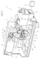
- Number 1 in Figure 1 indicates as a whole an electric vehicle steering lock connected to a known steering assembly, a steering shaft of which is indicated 2 in the accompanying drawings and comprises a radial seat 3 ( Figure 2).
- Steering lock 1 comprises an outer casing 4, which defines an outer seat 5 (Figure 1) in which shaft 2 is retained by a known connecting assembly not shown, and houses an elongated member 6 for angularly locking shaft 2 with respect to casing 4.
- Member 6 is fitted to casing 4 to slide axially in a direction A ( Figure 2) perpendicular to shaft 2, and is movable, by an actuating assembly 8, between a forward angular lock position projecting inside seat 5 and engaging radial seat 3 ( Figure 2), and a withdrawn rest position allowing shaft 2 to rotate freely with respect to casing 4.
- actuating assembly 8 comprises a spring 9 for pushing member 6 into the forward position; and an electric motor 10 controlled by an electronic drive circuit 11 having a first power connector 12, and a second connector 13 for receiving signals and commands from a known central control unit 14 (shown schematically) on the vehicle.
- Motor 10 comprises an outer casing fitted integrally to an inner surface of casing 4; and an output shaft 15 perpendicular to both direction A and shaft 2, and connected to member 6 by a mechanical transmission 16.
- Transmission 16 forms part of assembly 8, and comprises a rack-and-sprocket assembly 18 in turn comprising a sprocket 19 fitted to casing 4 to rotate about an axis parallel to and separated transversely from output shaft 15.
- Assembly 18 also comprises a rack 20, which meshes with sprocket 19, extends in contact with member 6 to define an extension of member 6, and is connected to member 6 by a guide-and-slide assembly 22 enabling rack 20 to move, with respect to member 6 and parallel to direction A, between a withdrawn axial limit position and a forward axial limit position.
- guide-and-slide assembly 22 comprises a slot 23 formed in rack 20, parallel to direction A and through the teeth of rack 20; and a pin 24 fitted integrally to member 6 and engaging slot 23 in axially sliding manner.
- member 6 is retained, in use, in the withdrawn position by a releasable mechanical retaining device 25 comprising a tooth 26, which is fitted in sliding manner to casing 4 and is pushed by a compression spring 28 into a forward lock position engaging a lateral seat 27 on member 6, and into a withdrawn rest position by an inclined surface 29 of rack 20, which acts as a withdrawing cam as rack 20 moves with respect to member 6.
- the withdrawn position of member 6 is detected by a known presence sensor 31 - conveniently a photodiode or microswitch - which forms part of circuit 11, is activated by an appendix 32 on rack 20, and emits a stop signal to stop motor 10 upon member 6 reaching the withdrawn position.
- transmission 16 also comprises two pairs of gears 33 and 34, which are interposed between motor 10 and sprocket 19 and define respective stages for reducing the speed of motor 10. More specifically, pair 33 comprises a drive gear 35 fitted to output shaft 15 of motor 10; and a driven gear 36 fitted to an intermediate shaft 37 fitted in rotary and axially-fixed manner to casing 4. Intermediate shaft 37 is also fitted with a drive gear 38 of pair 34, a driven gear 39 of which is connected integrally to and coaxially with sprocket 19.
- an electromechanical device 40 housed in casing 4 and comprising a lock pin 41, which is connected integrally to an output member of an electromagnetic linear actuator 42 controlled by electronic circuit 11 and for moving pin 41 between a forward work position in which pin 41 extends through a hole 43 formed in gear 39, and a withdrawn rest position allowing gear 39 to rotate freely.
- the forward position of pin 41 is detected by a microswitch 44, which forms part of circuit 11 and, upon pin 41 reaching the forward position, is switched by an outer radial flange 45 on the output member of actuator 42 to stop both actuator 42 and motor 10.
- steering lock 1 Operation of steering lock 1 will now be described as of a lock condition in which member 6 and rack 20 are in their forward positions, and pin 41 and tooth 26 are maintained in their withdrawn rest positions by actuator 42 and rack 20 respectively.
- circuit 11 activates motor 10 to withdraw rack 20, which, in opposition to spring 9 and by means of pin 24, draws member 6 along with it into the withdrawn position, in which member 6 is locked mechanically by tooth 26 clicking inside seat 27.
- circuit 11 receives the signal from sensor 31 and provides for deactivating motor 10 and activating electromagnetic linear actuator 42, which inserts pin 41 inside hole 43 to lock transmission 16. Insertion of pin 41 inside hole 43, i.e. correct operation of electromagnetic linear actuator 42, is controlled by microswitch 44.
- central control unit 14 emits another consent signal, so that circuit 11 first operates actuator 42 to withdraw pin 41 from hole 43, and then operates motor 10, which, rotating in the opposite direction to before, first moves rack 20 forward with respect to member 6, without moving member 6 from the withdrawn position.
- circuit 11 first operates actuator 42 to withdraw pin 41 from hole 43, and then operates motor 10, which, rotating in the opposite direction to before, first moves rack 20 forward with respect to member 6, without moving member 6 from the withdrawn position.
- surface 29 of the rack gradually moves the tooth into the withdrawn position to release member 6, which, pushed by spring 9, moves forward with respect to rack 20 and clicks into seat 3.
- steering lock 1 described is therefore extremely straightforward and cheap to produce, and extremely efficient, reliable and, above all, safe.
- steering lock 1 described comprises two in-series devices for retaining member 6 in the withdrawn release position : one electromagnetic, and which can only be deactivated by a consent signal supplied to electronic circuit 11 by central control unit 14 of the vehicle; and the other purely mechanical, and which is deactivated by the initial movement of rack 20.
- the locking of transmission 16 by actuator 42 is controlled each time by microswitch 44.
- seat 5 on casing 4 being identical to that of conventional steering locks, enables an electric steering lock to be obtained which can be substituted for a conventional steering lock with no alterations to either the casing or the steering column.
- steering lock 1 as described herein without, however, departing from the scope of the accompanying Claims.
- different devices may be provided for connecting rack 20 to member 6; and a different transmission may be provided between motor 10 and rack-and-sprocket assembly 18.
Landscapes
- Engineering & Computer Science (AREA)
- Mechanical Engineering (AREA)
- Lock And Its Accessories (AREA)
Applications Claiming Priority (2)
| Application Number | Priority Date | Filing Date | Title |
|---|---|---|---|
| IT2000TO000712A IT1320542B1 (it) | 2000-07-18 | 2000-07-18 | Bloccasterzo elettrico per veicoli. |
| ITTO000712 | 2000-07-18 |
Publications (2)
| Publication Number | Publication Date |
|---|---|
| EP1174314A2 true EP1174314A2 (fr) | 2002-01-23 |
| EP1174314A3 EP1174314A3 (fr) | 2002-07-24 |
Family
ID=11457926
Family Applications (1)
| Application Number | Title | Priority Date | Filing Date |
|---|---|---|---|
| EP01117293A Withdrawn EP1174314A3 (fr) | 2000-07-18 | 2001-07-17 | Verrou de direction électrique pour véhicule |
Country Status (2)
| Country | Link |
|---|---|
| EP (1) | EP1174314A3 (fr) |
| IT (1) | IT1320542B1 (fr) |
Cited By (15)
| Publication number | Priority date | Publication date | Assignee | Title |
|---|---|---|---|---|
| DE10356660A1 (de) * | 2003-12-04 | 2005-07-14 | Siemens Ag | Elektrische Lenkungsverriegelung mit einem Kurvengetriebe |
| EP1621423A1 (fr) * | 2004-07-29 | 2006-02-01 | Kabushiki Kaisha Tokai Rika Denki Seisakusho | Antivol de direction |
| EP1621421A1 (fr) * | 2004-07-29 | 2006-02-01 | Kabushiki Kaisha Tokai Rika Denki Seisakusho | Antivol de direction |
| DE102004031238A1 (de) * | 2004-06-29 | 2006-02-09 | Daimlerchrysler Ag | Vorrichtung zum Verriegeln und/oder Entriegeln eines Lenkrades eines Kraftfahrzeugs |
| WO2007118840A1 (fr) * | 2006-04-13 | 2007-10-25 | Huf Hülsbeck & Fürst Gmbh & Co. Kg | Dispositif de verrouillage |
| DE102006042511A1 (de) * | 2006-09-07 | 2008-03-27 | Huf Hülsbeck & Fürst Gmbh & Co. Kg | Kompakte Verriegelungsvorrichtung |
| DE102007053064B4 (de) * | 2006-11-08 | 2010-12-23 | Kabushiki Kaisha Honda Lock | Elektrisches Lenkschlosssystem |
| CN101811528B (zh) * | 2009-02-24 | 2012-05-23 | 台达电子工业股份有限公司 | 机车电子式龙头锁 |
| CN101823521B (zh) * | 2009-03-04 | 2012-09-26 | 台达电子工业股份有限公司 | 机车电子式龙头锁 |
| US8424348B2 (en) | 2010-01-27 | 2013-04-23 | Strattec Security Corporation | Steering lock |
| EP1807289B2 (fr) † | 2004-11-05 | 2014-02-12 | Valeo Sicherheitssysteme GmbH | Antivol de direction |
| WO2016086919A1 (fr) * | 2014-12-03 | 2016-06-09 | Huf Hülsbeck & Fürst Gmbh & Co.Kg | Dispositif de verrouillage de la direction d'un véhicule |
| US9457833B2 (en) | 2010-01-27 | 2016-10-04 | Strattec Security Corporation | Steering lock |
| EP3243712A1 (fr) * | 2016-05-10 | 2017-11-15 | HUF Hülsbeck & Fürst GmbH & Co. KG | Élément de déplacement pour un antivol électrique de direction |
| CN108798308A (zh) * | 2018-05-31 | 2018-11-13 | 烟台三环锁业集团股份有限公司 | 一种汽车门锁的驱动机构 |
Family Cites Families (3)
| Publication number | Priority date | Publication date | Assignee | Title |
|---|---|---|---|---|
| JPS5914553A (ja) * | 1982-07-15 | 1984-01-25 | Kokusan Kinzoku Kogyo Co Ltd | キ−レスステアリングロツク装置 |
| GB9105578D0 (en) * | 1991-03-15 | 1991-05-01 | Tobin Mark I | Security system |
| EP0844154B1 (fr) * | 1996-11-13 | 2003-05-14 | Kabushiki Kaisha Tokai Rika Denki Seisakusho | Verrou de direction |
-
2000
- 2000-07-18 IT IT2000TO000712A patent/IT1320542B1/it active
-
2001
- 2001-07-17 EP EP01117293A patent/EP1174314A3/fr not_active Withdrawn
Non-Patent Citations (1)
| Title |
|---|
| None |
Cited By (25)
| Publication number | Priority date | Publication date | Assignee | Title |
|---|---|---|---|---|
| DE10356660B4 (de) * | 2003-12-04 | 2005-12-08 | Siemens Ag | Elektrische Lenkungsverriegelung mit einem Kurvengetriebe |
| DE10356660A1 (de) * | 2003-12-04 | 2005-07-14 | Siemens Ag | Elektrische Lenkungsverriegelung mit einem Kurvengetriebe |
| DE102004031238A1 (de) * | 2004-06-29 | 2006-02-09 | Daimlerchrysler Ag | Vorrichtung zum Verriegeln und/oder Entriegeln eines Lenkrades eines Kraftfahrzeugs |
| CN100423974C (zh) * | 2004-07-29 | 2008-10-08 | 株式会社东海理化电机制作所 | 转向锁定装置 |
| EP1621423A1 (fr) * | 2004-07-29 | 2006-02-01 | Kabushiki Kaisha Tokai Rika Denki Seisakusho | Antivol de direction |
| EP1621421A1 (fr) * | 2004-07-29 | 2006-02-01 | Kabushiki Kaisha Tokai Rika Denki Seisakusho | Antivol de direction |
| US7086256B2 (en) | 2004-07-29 | 2006-08-08 | Kabushiki Kaisha Tokai Rika Denki Seisakusho | Steering lock |
| US7310979B2 (en) | 2004-07-29 | 2007-12-25 | Kabushiki Kaisha Tokai Rika Denki Seisakusho | Steering lock |
| CN100374331C (zh) * | 2004-07-29 | 2008-03-12 | 株式会社东海理化电机制作所 | 转向锁定装置 |
| EP1807289B2 (fr) † | 2004-11-05 | 2014-02-12 | Valeo Sicherheitssysteme GmbH | Antivol de direction |
| WO2007118840A1 (fr) * | 2006-04-13 | 2007-10-25 | Huf Hülsbeck & Fürst Gmbh & Co. Kg | Dispositif de verrouillage |
| KR101353876B1 (ko) * | 2006-04-13 | 2014-01-20 | 후프 휼스벡 운트 휘르스트 게엠베하 운트 콤파니 카게 | 록킹 장치 |
| DE102006042511B4 (de) * | 2006-09-07 | 2019-05-16 | Huf Hülsbeck & Fürst Gmbh & Co. Kg | Kompakte Verriegelungsvorrichtung |
| DE102006042511A1 (de) * | 2006-09-07 | 2008-03-27 | Huf Hülsbeck & Fürst Gmbh & Co. Kg | Kompakte Verriegelungsvorrichtung |
| DE102007053064B9 (de) * | 2006-11-08 | 2011-07-14 | Kabushiki Kaisha Honda Lock | Elektrisches Lenkschlosssystem |
| DE102007053064B4 (de) * | 2006-11-08 | 2010-12-23 | Kabushiki Kaisha Honda Lock | Elektrisches Lenkschlosssystem |
| CN101811528B (zh) * | 2009-02-24 | 2012-05-23 | 台达电子工业股份有限公司 | 机车电子式龙头锁 |
| CN101823521B (zh) * | 2009-03-04 | 2012-09-26 | 台达电子工业股份有限公司 | 机车电子式龙头锁 |
| US8424348B2 (en) | 2010-01-27 | 2013-04-23 | Strattec Security Corporation | Steering lock |
| US9457833B2 (en) | 2010-01-27 | 2016-10-04 | Strattec Security Corporation | Steering lock |
| WO2016086919A1 (fr) * | 2014-12-03 | 2016-06-09 | Huf Hülsbeck & Fürst Gmbh & Co.Kg | Dispositif de verrouillage de la direction d'un véhicule |
| EP3243712A1 (fr) * | 2016-05-10 | 2017-11-15 | HUF Hülsbeck & Fürst GmbH & Co. KG | Élément de déplacement pour un antivol électrique de direction |
| CN107415888A (zh) * | 2016-05-10 | 2017-12-01 | 胡夫·许尔斯贝克和福斯特有限及两合公司 | 用于电动方向盘锁的转换元件 |
| CN108798308A (zh) * | 2018-05-31 | 2018-11-13 | 烟台三环锁业集团股份有限公司 | 一种汽车门锁的驱动机构 |
| CN108798308B (zh) * | 2018-05-31 | 2024-02-02 | 烟台三环锁业集团股份有限公司 | 一种汽车门锁的驱动机构 |
Also Published As
| Publication number | Publication date |
|---|---|
| IT1320542B1 (it) | 2003-12-10 |
| ITTO20000712A1 (it) | 2002-01-18 |
| EP1174314A3 (fr) | 2002-07-24 |
| ITTO20000712A0 (it) | 2000-07-18 |
Similar Documents
| Publication | Publication Date | Title |
|---|---|---|
| EP1174314A2 (fr) | Verrou de direction électrique pour véhicule | |
| JP6455059B2 (ja) | シフト装置 | |
| KR100801572B1 (ko) | 자동차 스티어링 샤프트용 잠금 장치 | |
| EP0916353B1 (fr) | Appareil de transport de liquides | |
| CN106133407B (zh) | 单马达变速器执行器及其控制方法 | |
| US9169879B2 (en) | Dog clutch control apparatus for automated transmission | |
| CN101959725B (zh) | 用于控制锁止件的方法及装置 | |
| RU2759611C2 (ru) | Электроприводный блокируемый дифференциал с механизмом обнаружения блокировки | |
| JP2016539836A (ja) | 車両のオートマチックトランスミッションの操作要素をロックするための装置、このような装置を運転するための方法及び車両のオートマチックトランスミッションをシフトするためのシフト装置 | |
| KR20190119125A (ko) | 자동 주차 복귀 회전 및 레버식 시프터 | |
| US10619737B2 (en) | Park pawl engagement and sensor assembly and method | |
| WO2009070795A1 (fr) | Actionneur linéaire de type manivelle | |
| US12410857B2 (en) | Lock detection mechanism for electronic locking differential | |
| CN105324293A (zh) | 具有空心轴电动机的双小齿轮转向机构 | |
| US8047028B2 (en) | Steering shaft lock actuator | |
| WO1991008403A1 (fr) | Mecanisme d'inversion de marche et d'arret pour commande electrique | |
| KR100833383B1 (ko) | 차량의 스티어링 락장치 | |
| WO2017142533A1 (fr) | Ensemble et procédé de détection de mouvement d'un élément d'arbre | |
| KR20100024598A (ko) | 차량용 스티어링 락장치 | |
| KR102318848B1 (ko) | 도어락의 클러치 모듈조립체 | |
| US11231088B2 (en) | Method for engaging two gear elements and driving device implementing such a method | |
| ITTO990265A1 (it) | Dispositivo bloccasterzo per un gruppo di sterzatura di un veicolo | |
| EP1273493B1 (fr) | Dispositif perfectionné de verrouillage de la colonne de direction d'un véhicule | |
| CN112088265B (zh) | 换挡挡位控制装置 | |
| CN108749763B (zh) | 用于锁定和释放机动车的功能重要的构件的装置 |
Legal Events
| Date | Code | Title | Description |
|---|---|---|---|
| PUAI | Public reference made under article 153(3) epc to a published international application that has entered the european phase |
Free format text: ORIGINAL CODE: 0009012 |
|
| AK | Designated contracting states |
Kind code of ref document: A2 Designated state(s): AT BE CH CY DE DK ES FI FR GB GR IE IT LI LU MC NL PT SE TR |
|
| AX | Request for extension of the european patent |
Free format text: AL;LT;LV;MK;RO;SI |
|
| PUAL | Search report despatched |
Free format text: ORIGINAL CODE: 0009013 |
|
| AK | Designated contracting states |
Kind code of ref document: A3 Designated state(s): AT BE CH CY DE DK ES FI FR GB GR IE IT LI LU MC NL PT SE TR |
|
| AX | Request for extension of the european patent |
Free format text: AL;LT;LV;MK;RO;SI |
|
| 17P | Request for examination filed |
Effective date: 20030123 |
|
| AKX | Designation fees paid |
Designated state(s): AT BE CH CY DE DK ES FI FR GB GR IE IT LI LU MC NL PT SE TR |
|
| 17Q | First examination report despatched |
Effective date: 20030422 |
|
| RAP1 | Party data changed (applicant data changed or rights of an application transferred) |
Owner name: TRW AUTOMOTIVE ITALIA S.P.A |
|
| GRAP | Despatch of communication of intention to grant a patent |
Free format text: ORIGINAL CODE: EPIDOSNIGR1 |
|
| STAA | Information on the status of an ep patent application or granted ep patent |
Free format text: STATUS: THE APPLICATION IS DEEMED TO BE WITHDRAWN |
|
| 18D | Application deemed to be withdrawn |
Effective date: 20060418 |