EP1174321A1 - Soupape à deux étages - Google Patents
Soupape à deux étages Download PDFInfo
- Publication number
- EP1174321A1 EP1174321A1 EP01115591A EP01115591A EP1174321A1 EP 1174321 A1 EP1174321 A1 EP 1174321A1 EP 01115591 A EP01115591 A EP 01115591A EP 01115591 A EP01115591 A EP 01115591A EP 1174321 A1 EP1174321 A1 EP 1174321A1
- Authority
- EP
- European Patent Office
- Prior art keywords
- pressure
- valve
- stage
- relief
- brake
- Prior art date
- Legal status (The legal status is an assumption and is not a legal conclusion. Google has not performed a legal analysis and makes no representation as to the accuracy of the status listed.)
- Granted
Links
Images



Classifications
-
- B—PERFORMING OPERATIONS; TRANSPORTING
- B60—VEHICLES IN GENERAL
- B60T—VEHICLE BRAKE CONTROL SYSTEMS OR PARTS THEREOF; BRAKE CONTROL SYSTEMS OR PARTS THEREOF, IN GENERAL; ARRANGEMENT OF BRAKING ELEMENTS ON VEHICLES IN GENERAL; PORTABLE DEVICES FOR PREVENTING UNWANTED MOVEMENT OF VEHICLES; VEHICLE MODIFICATIONS TO FACILITATE COOLING OF BRAKES
- B60T11/00—Transmitting braking action from initiating means to ultimate brake actuator without power assistance or drive or where such assistance or drive is irrelevant
- B60T11/10—Transmitting braking action from initiating means to ultimate brake actuator without power assistance or drive or where such assistance or drive is irrelevant transmitting by fluid means, e.g. hydraulic
- B60T11/16—Master control, e.g. master cylinders
- B60T11/224—Master control, e.g. master cylinders with pressure-varying means, e.g. with two stage operation provided by use of different piston diameters including continuous variation from one diameter to another
Definitions
- the invention relates to a two-stage valve, in particular a brake valve, with two cross-sectional levels, the Cross sections with one valve actuation one after the other take effect by first enlarging a pressure room Cross section, the so-called filling level, for filling a system is used and then a pressure room smaller Cross section, the so-called pressure stage, to Applying the working pressure is used.
- a Filling level relief valve arranged, which a Valve element and one acting on the valve element Relief piston has.
- the valve element is on the one hand the pressure in the reservoir and a spring force and on the other hand exposed to the pressure in the filling stage.
- the Relief piston is one end of the pressure in the reservoir exposed and can at the other end the pressure in the compression stage get abandoned. It has a free end on that Valve element in order to with increasing differential pressure between the pressure stage and the filling stage the valve element in To push opening direction.
- Such a valve designed as a brake valve goes out US-A-4,455,831, in which the valve element as a ball is formed, which has a valve seat in the valve housing interacts.
- the valve element opens when the fluid pressure reached a certain manipulated value within the filling level.
- the relief piston is a stepped piston whose thicker Piston section is guided in a cylinder bore and a Has annular groove that receives a seal. The thinner The end of the piston engages with the ball. With increasing pressure in the pressure stage the Relief piston with increasing force against the ball in Opening direction pressed. This is said to be a constant Operation guaranteed even when the brakes are applied suddenly become.
- By using the seal on the relief piston however, there are friction-related impairments such as Hysteresis and "spongy" response.
- EP-A-0 534 309 describes a two-stage brake valve described, in which between the filling level and the Reservoir a check valve is arranged, which contains a ball by the force of a spring on one Valve seat is pressed and at a predetermined limit pressure opens.
- the closing force of the spring is in Dependence of the pressure in the pressure stage controllable in the this pressure acts on a spool, which in turn relieved the spring. Seals are also used with this solution provided to avoid leakage what the mentioned Brings disadvantages.
- the object underlying the invention is seen in to specify a valve of the type mentioned, through which the disadvantages mentioned above can be avoided.
- the valve should have a direct response and have a reduced hysteresis behavior.
- both the valve element as well as the relief piston designed as a cylinder body.
- Each of these cylinder bodies is in an associated one Cylinder bore of the valve body in the manner of a sliding fit guided.
- a clearance fit is suitable as a sliding fit the the space between the cylinder piston and the associated hole is so small that a Liquid passage is largely avoided, so no Sealing element must be used, and yet a lightweight Moving the cylinder piston is possible.
- the holes are preferably finely ground with a reamer.
- relatively long cylinder bodies are preferably used. This forms between the hole and the Cylinder body a long channel with a large sealing length , which makes it difficult for liquid to pass through.
- the valve By eliminating the sealing elements, the valve reacts in its response behavior directly to actuation forces.
- the Hysteresis behavior is significantly reduced and the braking force is easier to dose.
- the invention Valve with its filling level relief valve a very simple, inexpensive to manufacture, from a few components existing structure.
- a particularly advantageous embodiment of the invention results is characterized in that at least one of the two cylinder bodies is a needle roller.
- the cylinder body thus consists of a commercially available high-precision component, which as Mass product is commercially available inexpensively.
- Needle roller bearings are usually relatively long, one results large sealing length, which together with the accuracy of fit finely rubbed hole has a sealing effect without additional sealing element, especially without an elastomer seal, gets along.
- On the discharge piston facing Side of the valve element is one with the relief channel cooperating control edge formed over the at Reaching the limit pressure a connection between the Filling stage and the reservoir is made.
- Valves in accordance with the invention are advantageously used in Vehicles, especially in agricultural or industrial vehicles such as agricultural tractors, as brake valves Application.
- the respective stand over a brake compensation channel Compression sides of the two receiving the relief pistons Cylinder bores hydraulically connected to each other. This enables both brake circuits to be dependent on the respective Brake pedal travel are coupled together to ensure that both brake circuits are supplied with the same pressure and a "skewing" when braking is avoided.
- the two Filling level relief valves are out of tune with each other and open at different pressures. For example expressly by using springs with different Spring constant and / or by specifying different ones Rest positions for the two valve elements. hereby can the reversal process between filling level and Extend pressure level over a larger pressure range and steady so that for the operator of the Switching process is no longer noticeable.
- valve units 11, 13 each by a associated right or left brake pedal are actuated to to enable a steering brake function in a known manner.
- each Valve unit 11, 13 contains two gear ratios, which Combination of low pedal travel and low forces allow.
- the step master cylinder is one of the two Valve units 11, 13 shown, which two pistons of different diameters. This is what it is about a filling piston 10 large diameter and one Pressure piston 12 of smaller diameter.
- the two pistons 10, 12 assigned pressure rooms are with filling level 14 and Pressure stage 16 designated.
- the filling stage 14 With the piston movement to the left, the filling stage 14 builds up a pressure to open a check valve 20, so that brake fluid from the filling stage 14 through the Check valve 20, the pressure stage 16 and a fitting 22 for Brake not shown flows and a brake disc Plant brings. If the brake disc is in contact, none can significant amount of liquid flow away so that the Pressure in the filling stage 14 and in the pressure stage 16 up to one Limit pressure continues to rise.
- the limit pressure opens a fill level relief valve shown in Fig. 2 24 and connects the filling stage 14 to a storage container 26.
- the check valve 20 and the closes Pressure in pressure stage 16 increases with increasing Brake pedal force continues to increase, so that the desired braking effect entry.
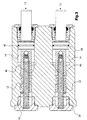
- the filling level relief valve 24 shown in FIG. 2 contains a large cylinder body as valve element 28 Diameter and one as a relief pressure piston 30 trained cylinder body of smaller diameter.
- the Valve element 28 is in a larger cylinder bore 32 and the relief pressure piston 30 is in a cylinder bore 34 smaller diameter can be moved lengthways.
- Both Cylinder bodies 28, 30 are commercially available Needle roller bearings that comply with high manufacturing tolerances.
- the Cylinder bores 32, 34 are aligned with one another and form one Stepped bore. They point in terms of their axial Alignment with a high level of manufacturing precision finely grated. They form with the associated cylinder bodies 28, 30 high precision sliding seals, one Prevent the passage of liquids as much as possible.
- the stepped bore 32, 34 is through a plug 36 locked.
- the plug 36 carries one into the cylinder bore 32 protruding approach 38, the axial movement of the Valve element 28 limited. Is concentric to approach 38 a helical compression spring 40 arranged between the plug 36 and the valve element 28 is clamped and that Valve element 28 pushes to the left, away from the plug 36.
- the larger cylinder bore 32 is via a sump channel 42 and a relief channel 44 with the reservoir 26 and over an only partially recognizable filling stage channel 46 with the Fill level 14 connected.
- the sump channel 42 opens into the larger one Cylinder bore 32 in the area of the stopper 38.
- the Sump channel 42 is not through valve element 28 lockable so that the fluid pressure in the reservoir always on the right end of the valve element 28 pending.
- the filling stage channel 46 opens into the larger one Cylinder bore 32 in an area to the left of that Valve element 28 so that the fluid pressure in the Fill level 14 constantly on the left side of the Valve element 28 bears.
- the relief channel 44 is closed by the valve element 28 when this is in the rest position shown in Fig. 2.
- the valve element 28 moves to the right and opens the Relief channel 44.
- the opening limit pressure depends on the pressure of the reservoir 26 and the force of the compression spring 40.
- the left end 47 of the smaller cylinder bore 34 stands with the brake compensation channel 19 in connection. If the brake piston 10, 12 is actuated and the second control edge 21 den Brake equalization channel 19 connects to pressure stage 16 on the left end face of the relief pressure piston 30 Pressure of pressure level 16 on. On the right front of the Relief pressure piston 30, however, the pressure of the Fill level 14. If the pressure of pressure levels 16 is greater than the pressure of the filling stage 14 becomes the relief pressure piston 30 pressed against the valve element 28. With increasing Pressure difference, the counterforce of the compression spring 40 is increasing compensated so that the required for the valve element 28 Opening pressure decreases and the pressure of the filling stage 14 over the Control edge 49 of the valve element 28 and the relief channel 44 will be gradually dismantled.
- the two compression springs 40 of the two valve units 11, 13 can have somewhat different spring constants, so that the Valve elements 28 react differently and not open at the same time but at different times. This leads to a further stabilization of the braking force characteristic, so that the transition from the filling level to the pressure level for the Operator is no longer noticeable.
- the plug 36 and / or the compression springs 40 of the two valve units 11, 13 different lengths have, so that the axial rest position, d. H. the situation in depressurized state of the two valve elements 28 is different.
- the filling stage 14 is with the reservoir 26 on Suction valve 52 in connection, via which when loosening the Brake pedal brake fluid from the reservoir 26 in the Filling stage 14 is sucked so that the piston 10 in its Starting position can return.
Landscapes
- Engineering & Computer Science (AREA)
- Transportation (AREA)
- Mechanical Engineering (AREA)
- Transmission Of Braking Force In Braking Systems (AREA)
- Valves And Accessory Devices For Braking Systems (AREA)
- Feeding And Controlling Fuel (AREA)
Applications Claiming Priority (2)
| Application Number | Priority Date | Filing Date | Title |
|---|---|---|---|
| DE10034787 | 2000-07-18 | ||
| DE10034787A DE10034787A1 (de) | 2000-07-18 | 2000-07-18 | Zweistufiges Ventil |
Publications (2)
| Publication Number | Publication Date |
|---|---|
| EP1174321A1 true EP1174321A1 (fr) | 2002-01-23 |
| EP1174321B1 EP1174321B1 (fr) | 2003-05-14 |
Family
ID=7649245
Family Applications (1)
| Application Number | Title | Priority Date | Filing Date |
|---|---|---|---|
| EP01115591A Expired - Lifetime EP1174321B1 (fr) | 2000-07-18 | 2001-06-28 | Soupape à deux étages |
Country Status (7)
| Country | Link |
|---|---|
| US (1) | US6502396B2 (fr) |
| EP (1) | EP1174321B1 (fr) |
| AT (1) | ATE240228T1 (fr) |
| BR (1) | BR0102932A (fr) |
| CA (1) | CA2352635A1 (fr) |
| DE (2) | DE10034787A1 (fr) |
| MX (1) | MXPA01007296A (fr) |
Families Citing this family (4)
| Publication number | Priority date | Publication date | Assignee | Title |
|---|---|---|---|---|
| JP4385001B2 (ja) * | 2005-03-31 | 2009-12-16 | 日信工業株式会社 | 液圧ブースタ |
| CA3023021C (fr) * | 2016-05-04 | 2020-12-29 | Ginda New-Tech Co., Ltd. | Dispositif de frein hydraulique a differentiel de temps et assemblage associe |
| CN108860036B (zh) * | 2018-07-26 | 2023-08-29 | 重庆交通职业学院 | 一种汽车防撞梁用可调阻尼式液压吸能机构 |
| CN112810591A (zh) * | 2021-03-05 | 2021-05-18 | 江苏沃得农业机械股份有限公司 | 一种单路二级压力增压制动泵 |
Citations (2)
| Publication number | Priority date | Publication date | Assignee | Title |
|---|---|---|---|---|
| US4455831A (en) * | 1981-04-14 | 1984-06-26 | Akebono Brake Industry Co., Ltd. | Differential master cylinder |
| US5239828A (en) * | 1991-09-27 | 1993-08-31 | Deere & Company | Two-stage valve |
Family Cites Families (1)
| Publication number | Priority date | Publication date | Assignee | Title |
|---|---|---|---|---|
| DE4130832C1 (fr) * | 1991-09-17 | 1993-05-13 | Deere & Co., Moline, Ill., Us, Niederlassung Deere & Co. European Office, 6800 Mannheim, De |
-
2000
- 2000-07-18 DE DE10034787A patent/DE10034787A1/de not_active Withdrawn
-
2001
- 2001-06-22 US US09/888,132 patent/US6502396B2/en not_active Expired - Lifetime
- 2001-06-28 AT AT01115591T patent/ATE240228T1/de not_active IP Right Cessation
- 2001-06-28 EP EP01115591A patent/EP1174321B1/fr not_active Expired - Lifetime
- 2001-06-28 DE DE50100240T patent/DE50100240D1/de not_active Expired - Lifetime
- 2001-07-06 CA CA002352635A patent/CA2352635A1/fr not_active Abandoned
- 2001-07-17 BR BR0102932-0A patent/BR0102932A/pt not_active Application Discontinuation
- 2001-07-18 MX MXPA01007296A patent/MXPA01007296A/es unknown
Patent Citations (2)
| Publication number | Priority date | Publication date | Assignee | Title |
|---|---|---|---|---|
| US4455831A (en) * | 1981-04-14 | 1984-06-26 | Akebono Brake Industry Co., Ltd. | Differential master cylinder |
| US5239828A (en) * | 1991-09-27 | 1993-08-31 | Deere & Company | Two-stage valve |
Also Published As
| Publication number | Publication date |
|---|---|
| US20020007635A1 (en) | 2002-01-24 |
| DE10034787A1 (de) | 2002-01-31 |
| DE50100240D1 (de) | 2003-06-18 |
| CA2352635A1 (fr) | 2002-01-18 |
| ATE240228T1 (de) | 2003-05-15 |
| US6502396B2 (en) | 2003-01-07 |
| MXPA01007296A (es) | 2003-05-19 |
| EP1174321B1 (fr) | 2003-05-14 |
| BR0102932A (pt) | 2002-03-05 |
Similar Documents
| Publication | Publication Date | Title |
|---|---|---|
| EP0744009B1 (fr) | Vanne de regulation a etages multiples | |
| DE2602050B2 (de) | Hydraulisches Verstärkerventil, insbesondere für eine hydraulische Bremsanlage eines Kraftfahrzeuges | |
| EP0368120B1 (fr) | Valve | |
| DE2558034A1 (de) | Druckreduzierungseinrichtung, insbesondere fuer hydraulische bremssysteme in kraftfahrzeugen | |
| DE3133995A1 (de) | Druckventil fuer eine hydraulische zweikreis-bremsanlage | |
| DE69102079T2 (de) | Bremsventil mit Druckbegrenzungsfunktion. | |
| DE3116237A1 (de) | Abstroemventil-vorrichtung in einem schnell ansprechenden hauptzylinder | |
| EP1174321B1 (fr) | Soupape à deux étages | |
| DE69101351T2 (de) | Verfahren zum Einstellen des Anlegehubs eines Tandem-Hauptzylinders und Tandem-Hauptzylinder zur Durchführung des Verfahrens. | |
| DE3037485A1 (de) | Hauptbremszylinder | |
| DE2926539C2 (de) | Regelventil für Fahrzeugbremsanlagen mit zwei Bremskreisen | |
| DE2213367C3 (de) | Druckminderventil für druckmittelbetatigbare Kraftfahrzeug-Bremsanlagen | |
| DE2932593C2 (de) | Drosseldruck-Regelventil für die hydraulische Steuereinrichtung eines automatischen Getriebes | |
| DE69013322T2 (de) | Druckentlastungsventil für Hydraulikfluid. | |
| DE2403430A1 (de) | Steuerventil mit abgestuftem druckanstieg | |
| DE2736095C3 (de) | Steuerventil für eine hydraulische Fahrzeugbremsanlage | |
| DE3878375T2 (de) | Proportionalventil zur verwendung bei blockierverhinderern. | |
| EP0534309B1 (fr) | Soupape à deux étages | |
| DE3029090C2 (fr) | ||
| DE69221377T2 (de) | Durchflussregelvorrichtung | |
| DE2508268C3 (de) | Steuerkolben fur hydraulische Druckmittelfolgesteuerungen, insbesondere für ein Lenkventil einer Servolenkeinrichtung von Fahrzeugen | |
| DE3836344C2 (fr) | ||
| DE2748698A1 (de) | Druckregulierventil | |
| DE19525582A1 (de) | Inchbremseinrichtung | |
| DE2426712B2 (de) | Servolenkeinrichtung für Fahrzeuge, insbesondere solche mit Speicher-Lenkungen |
Legal Events
| Date | Code | Title | Description |
|---|---|---|---|
| PUAI | Public reference made under article 153(3) epc to a published international application that has entered the european phase |
Free format text: ORIGINAL CODE: 0009012 |
|
| AK | Designated contracting states |
Kind code of ref document: A1 Designated state(s): AT BE CH CY DE DK ES FI FR GB GR IE IT LI LU MC NL PT SE TR |
|
| AX | Request for extension of the european patent |
Free format text: AL;LT;LV;MK;RO;SI |
|
| 17P | Request for examination filed |
Effective date: 20020723 |
|
| AKX | Designation fees paid |
Free format text: AT BE CH CY DE DK ES FI FR GB GR IE IT LI LU MC NL PT SE TR |
|
| GRAH | Despatch of communication of intention to grant a patent |
Free format text: ORIGINAL CODE: EPIDOS IGRA |
|
| GRAH | Despatch of communication of intention to grant a patent |
Free format text: ORIGINAL CODE: EPIDOS IGRA |
|
| GRAA | (expected) grant |
Free format text: ORIGINAL CODE: 0009210 |
|
| AK | Designated contracting states |
Designated state(s): AT BE CH CY DE DK ES FI FR GB GR IE IT LI LU MC NL PT SE TR |
|
| PG25 | Lapsed in a contracting state [announced via postgrant information from national office to epo] |
Ref country code: IT Free format text: LAPSE BECAUSE OF FAILURE TO SUBMIT A TRANSLATION OF THE DESCRIPTION OR TO PAY THE FEE WITHIN THE PRESCRIBED TIME-LIMIT;WARNING: LAPSES OF ITALIAN PATENTS WITH EFFECTIVE DATE BEFORE 2007 MAY HAVE OCCURRED AT ANY TIME BEFORE 2007. THE CORRECT EFFECTIVE DATE MAY BE DIFFERENT FROM THE ONE RECORDED. Effective date: 20030514 Ref country code: FR Free format text: LAPSE BECAUSE OF FAILURE TO SUBMIT A TRANSLATION OF THE DESCRIPTION OR TO PAY THE FEE WITHIN THE PRESCRIBED TIME-LIMIT Effective date: 20030514 Ref country code: NL Free format text: LAPSE BECAUSE OF FAILURE TO SUBMIT A TRANSLATION OF THE DESCRIPTION OR TO PAY THE FEE WITHIN THE PRESCRIBED TIME-LIMIT Effective date: 20030514 Ref country code: FI Free format text: LAPSE BECAUSE OF FAILURE TO SUBMIT A TRANSLATION OF THE DESCRIPTION OR TO PAY THE FEE WITHIN THE PRESCRIBED TIME-LIMIT Effective date: 20030514 Ref country code: IE Free format text: LAPSE BECAUSE OF FAILURE TO SUBMIT A TRANSLATION OF THE DESCRIPTION OR TO PAY THE FEE WITHIN THE PRESCRIBED TIME-LIMIT Effective date: 20030514 Ref country code: GB Free format text: LAPSE BECAUSE OF FAILURE TO SUBMIT A TRANSLATION OF THE DESCRIPTION OR TO PAY THE FEE WITHIN THE PRESCRIBED TIME-LIMIT Effective date: 20030514 Ref country code: TR Free format text: LAPSE BECAUSE OF FAILURE TO SUBMIT A TRANSLATION OF THE DESCRIPTION OR TO PAY THE FEE WITHIN THE PRESCRIBED TIME-LIMIT Effective date: 20030514 |
|
| REG | Reference to a national code |
Ref country code: GB Ref legal event code: FG4D Free format text: NOT ENGLISH |
|
| REG | Reference to a national code |
Ref country code: CH Ref legal event code: EP |
|
| REG | Reference to a national code |
Ref country code: IE Ref legal event code: FG4D Free format text: GERMAN |
|
| REF | Corresponds to: |
Ref document number: 50100240 Country of ref document: DE Date of ref document: 20030618 Kind code of ref document: P |
|
| PG25 | Lapsed in a contracting state [announced via postgrant information from national office to epo] |
Ref country code: AT Free format text: LAPSE BECAUSE OF NON-PAYMENT OF DUE FEES Effective date: 20030628 Ref country code: LU Free format text: LAPSE BECAUSE OF NON-PAYMENT OF DUE FEES Effective date: 20030628 Ref country code: CY Free format text: LAPSE BECAUSE OF FAILURE TO SUBMIT A TRANSLATION OF THE DESCRIPTION OR TO PAY THE FEE WITHIN THE PRESCRIBED TIME-LIMIT Effective date: 20030628 |
|
| PG25 | Lapsed in a contracting state [announced via postgrant information from national office to epo] |
Ref country code: MC Free format text: LAPSE BECAUSE OF NON-PAYMENT OF DUE FEES Effective date: 20030630 |
|
| PG25 | Lapsed in a contracting state [announced via postgrant information from national office to epo] |
Ref country code: GR Free format text: LAPSE BECAUSE OF FAILURE TO SUBMIT A TRANSLATION OF THE DESCRIPTION OR TO PAY THE FEE WITHIN THE PRESCRIBED TIME-LIMIT Effective date: 20030814 Ref country code: DK Free format text: LAPSE BECAUSE OF FAILURE TO SUBMIT A TRANSLATION OF THE DESCRIPTION OR TO PAY THE FEE WITHIN THE PRESCRIBED TIME-LIMIT Effective date: 20030814 Ref country code: PT Free format text: LAPSE BECAUSE OF FAILURE TO SUBMIT A TRANSLATION OF THE DESCRIPTION OR TO PAY THE FEE WITHIN THE PRESCRIBED TIME-LIMIT Effective date: 20030814 Ref country code: SE Free format text: LAPSE BECAUSE OF FAILURE TO SUBMIT A TRANSLATION OF THE DESCRIPTION OR TO PAY THE FEE WITHIN THE PRESCRIBED TIME-LIMIT Effective date: 20030814 |
|
| PG25 | Lapsed in a contracting state [announced via postgrant information from national office to epo] |
Ref country code: ES Free format text: LAPSE BECAUSE OF FAILURE TO SUBMIT A TRANSLATION OF THE DESCRIPTION OR TO PAY THE FEE WITHIN THE PRESCRIBED TIME-LIMIT Effective date: 20030825 |
|
| NLV1 | Nl: lapsed or annulled due to failure to fulfill the requirements of art. 29p and 29m of the patents act | ||
| GBV | Gb: ep patent (uk) treated as always having been void in accordance with gb section 77(7)/1977 [no translation filed] |
Effective date: 20030514 |
|
| BERE | Be: lapsed |
Owner name: *DEERE & CY Effective date: 20030630 |
|
| REG | Reference to a national code |
Ref country code: IE Ref legal event code: FD4D Ref document number: 1174321E Country of ref document: IE |
|
| PLBE | No opposition filed within time limit |
Free format text: ORIGINAL CODE: 0009261 |
|
| STAA | Information on the status of an ep patent application or granted ep patent |
Free format text: STATUS: NO OPPOSITION FILED WITHIN TIME LIMIT |
|
| 26N | No opposition filed |
Effective date: 20040217 |
|
| EN | Fr: translation not filed | ||
| PG25 | Lapsed in a contracting state [announced via postgrant information from national office to epo] |
Ref country code: CH Free format text: LAPSE BECAUSE OF NON-PAYMENT OF DUE FEES Effective date: 20050630 Ref country code: LI Free format text: LAPSE BECAUSE OF NON-PAYMENT OF DUE FEES Effective date: 20050630 |
|
| REG | Reference to a national code |
Ref country code: CH Ref legal event code: PL |
|
| PG25 | Lapsed in a contracting state [announced via postgrant information from national office to epo] |
Ref country code: BE Free format text: LAPSE BECAUSE OF NON-PAYMENT OF DUE FEES Effective date: 20030630 |
|
| PGFP | Annual fee paid to national office [announced via postgrant information from national office to epo] |
Ref country code: DE Payment date: 20200520 Year of fee payment: 20 |
|
| REG | Reference to a national code |
Ref country code: DE Ref legal event code: R071 Ref document number: 50100240 Country of ref document: DE |