EP1174572A2 - Schliesszylinder mit einer Anordnung zum kontaktlosen Übertragen eines Signals - Google Patents
Schliesszylinder mit einer Anordnung zum kontaktlosen Übertragen eines Signals Download PDFInfo
- Publication number
- EP1174572A2 EP1174572A2 EP01117887A EP01117887A EP1174572A2 EP 1174572 A2 EP1174572 A2 EP 1174572A2 EP 01117887 A EP01117887 A EP 01117887A EP 01117887 A EP01117887 A EP 01117887A EP 1174572 A2 EP1174572 A2 EP 1174572A2
- Authority
- EP
- European Patent Office
- Prior art keywords
- transmitting
- antenna
- knob
- locking cylinder
- receiving element
- Prior art date
- Legal status (The legal status is an assumption and is not a legal conclusion. Google has not performed a legal analysis and makes no representation as to the accuracy of the status listed.)
- Granted
Links
Images


Classifications
-
- E—FIXED CONSTRUCTIONS
- E05—LOCKS; KEYS; WINDOW OR DOOR FITTINGS; SAFES
- E05B—LOCKS; ACCESSORIES THEREFOR; HANDCUFFS
- E05B47/00—Operating or controlling locks or other fastening devices by electric or magnetic means
- E05B47/06—Controlling mechanically-operated bolts by electro-magnetically-operated detents
- E05B47/0611—Cylinder locks with electromagnetic control
- E05B47/0638—Cylinder locks with electromagnetic control by disconnecting the rotor
-
- E—FIXED CONSTRUCTIONS
- E05—LOCKS; KEYS; WINDOW OR DOOR FITTINGS; SAFES
- E05B—LOCKS; ACCESSORIES THEREFOR; HANDCUFFS
- E05B15/00—Other details of locks; Parts for engagement by bolts of fastening devices
- E05B15/02—Striking-plates; Keepers; Bolt staples; Escutcheons
-
- E—FIXED CONSTRUCTIONS
- E05—LOCKS; KEYS; WINDOW OR DOOR FITTINGS; SAFES
- E05B—LOCKS; ACCESSORIES THEREFOR; HANDCUFFS
- E05B47/00—Operating or controlling locks or other fastening devices by electric or magnetic means
- E05B47/06—Controlling mechanically-operated bolts by electro-magnetically-operated detents
- E05B47/0611—Cylinder locks with electromagnetic control
- E05B47/0615—Cylinder locks with electromagnetic control operated by handles, e.g. by knobs
-
- E—FIXED CONSTRUCTIONS
- E05—LOCKS; KEYS; WINDOW OR DOOR FITTINGS; SAFES
- E05B—LOCKS; ACCESSORIES THEREFOR; HANDCUFFS
- E05B47/00—Operating or controlling locks or other fastening devices by electric or magnetic means
- E05B2047/0048—Circuits, feeding, monitoring
- E05B2047/0065—Saving energy
-
- G—PHYSICS
- G07—CHECKING-DEVICES
- G07C—TIME OR ATTENDANCE REGISTERS; REGISTERING OR INDICATING THE WORKING OF MACHINES; GENERATING RANDOM NUMBERS; VOTING OR LOTTERY APPARATUS; ARRANGEMENTS, SYSTEMS OR APPARATUS FOR CHECKING NOT PROVIDED FOR ELSEWHERE
- G07C9/00—Individual registration on entry or exit
- G07C9/00174—Electronically operated locks; Circuits therefor; Nonmechanical keys therefor, e.g. passive or active electrical keys or other data carriers without mechanical keys
- G07C2009/00753—Electronically operated locks; Circuits therefor; Nonmechanical keys therefor, e.g. passive or active electrical keys or other data carriers without mechanical keys operated by active electrical keys
- G07C2009/00769—Electronically operated locks; Circuits therefor; Nonmechanical keys therefor, e.g. passive or active electrical keys or other data carriers without mechanical keys operated by active electrical keys with data transmission performed by wireless means
Definitions
- the invention relates to an arrangement for transmission a decoding signal for one by one Anti-pull fitting protected lock cylinder with a Transceiver unit for contactless reception of a Decoding signal, the at least one first transmission / Receiving element in the front End face region of the lock cylinder is arranged.
- the anti-pull fitting can be used as a core pull fitting be trained and part of a Rosette, which is only the area of the Locking cylinder covers. He can also Anti-pull fitting an insert in front of the locking cylinder have, which can be interchangeable. It will be in following spoken of a pull protection fitting without which is a limitation to its execution in is understandable to individual. Also in the following Transceiver element and antenna used synonymously.
- Such a locking cylinder with a transmitting / receiving element on the front of the locking cylinder is known for example from EP 0 187 363 B1.
- the arrangement is such that the transmitting / receiving element is arranged on the face to in to be in close contact with a transponder that is arranged in the key handle. This short distance is needed in the case of the relatively small Adequate signal transmission to antennas guarantee. For this reason, such Lock cylinder also not with an anti-pull fitting be protected, since this is the end face of the Lock cylinder essentially completely with metallic material covered. A contactless one Signal transmission is then no longer possible.
- the contactlessly transmitted decoding signal is used for Switching an electrically active drive element, Coupling element, end or locking element to to enable actuation of the locking cylinder.
- the decoding signal often becomes one used to create so-called access control systems create with which the individual closing processes can be checked and registered. Because of the required antenna arrangement on the face and the lack of protection of the Locking cylinders against pulling out have such electromechanical locking cylinder only one relatively low mechanical security. However, it does exist often the desire, even such electromechanical Lock cylinder, for example, outdoors to arrange in which increased mechanical security is required.
- knob cylinders which can be operated from at least one side with a knob are.
- Control electronics for evaluating the transponder signal arranged that with a key the above described type is transmitted.
- slip ring contacts Signal connection with the fixed part of the Lock cylinder and the transponder antenna on the opposite end of the lock cylinder. It has been shown that slip ring contacts are common Cause interference in the transmission of the signal.
- knob cylinders it is Decoding device often at a distance from the locking cylinder arranged, for example in the area of the door frame.
- the Decoding device can be a keypad or with a be equipped with a biometric sensor or via a Decoding element, for example a key or a chip card.
- a larger assembly effort for the locking cylinder and the related decoding device is required.
- the Control electronics and also the decoding sensor, for example the transponder antenna or a biometric sensor, for such electromechanical working lock cylinder housed in the knob become.
- the problem with such knob cylinders is then in the signal transmission from the fixed Lock cylinder part for the rotating knob.
- the invention is therefore based on the object Lock cylinder of the type described above train that a contactless transmission of the Decoding signal at an existing one Anti-pull fitting and also possible with a knob.
- the object is achieved according to the invention in a first Embodiment solved in that a second transmit / receive element on the front of the Anti-pull fitting is arranged, which in Signal connection with a third transmitting / receiving element is on the back of the anti-pull fitting, which is in Signal connection with the first transmitting / receiving element stands on the front of the locking cylinder.
- a second transmit / receive element on the front of the Anti-pull fitting is arranged, which in Signal connection with a third transmitting / receiving element is on the back of the anti-pull fitting, which is in Signal connection with the first transmitting / receiving element stands on the front of the locking cylinder.
- the connection between the two on the Anti-pull fitting arranged transmitting / receiving elements can be done for example by a signal cable that is guided through a hole or groove. This hole or groove causes only a slight weakening of the Anti-pull fitting, so that its protective function can be fully maintained.
- the transmitting / receiving element on the Front of the anti-pull fitting is arranged and in a direct signal connection with the transmitter / receiver unit it lock cylinder stands.
- the signal connection is detachable.
- the signal connection can be, for example, a signal cable include that through the anti-pull fitting from the transmitting / receiving element on the front of the Anti-pull fitting up to the transmitter / receiver unit of the Lock cylinder is guided. This can also be done Decoding signal are transmitted.
- the signal connection is a Contact arrangement includes, whose contacts so to the facing sides of the lock cylinder and the Anti-pull fitting are arranged that a Signal connection when installing the anti-pull fitting is effected on the lock cylinder.
- the contacts can, for example as resilient contact pins or in the form of a plug / coupling arrangement be trained.
- the transmission / reception element is on the front of the anti-pull fitting at least is partially located in the area that the Lock cylinder covered. This ensures that when using an active or passive transmitter on Key handle the required short distance can be observed. But it can also be provided be that the transmitting / receiving element on the Front of the anti-pull fitting in the Lock cylinder at least partially surrounding area is arranged. This can also result in a small distance to the active or passive transmitter of the key or another decoding element can be achieved.
- the signal transmission to the transmitting / receiving element on the The front of the anti-pull fitting is made expediently by a signal cable.
- the required hole or groove can preferably outside the area of the anti-pull fitting be arranged, which covers the lock cylinder. This ensures that a starting point of a Drawing tool that engage in the hole or groove could be outside the area where a drag the lock cylinder from the door or the like possible would.
- the transmission / reception element on the Anti-pull fitting can be arranged. However, it is useful if the transmission / reception element on the Front of the anti-pull fitting in a recess is arranged such that between the lock cylinder and Bottom surface of the depression still sufficient material is available.
- the transmission / reception element closes preferably flush with the surface of the Anti-pull fitting from so that on the one hand appealing appearance is achieved. On the other hand an accidental or deliberate destruction of the Transmit / receive element effectively prevented.
- the invention was based on a Lock cylinder described, the locking core by means of a key is to be operated. Here is that It is often necessary to provide an anti-pull fitting. However, essentially the same problem also occurs a locking cylinder, the locking nose with a Is to be operated knob. Here too it is often desirable and sometimes also required that the actuation first after receiving a corresponding decoding signal is possible. With such locking cylinders, the transmitting / receiving element is for receiving the decoding signal often arranged at a distance from the locking cylinder, for example in the area of the door frame in one Decoding apparatus.
- the decoding element for example a key, or a smart card, is in the area of the transmitting / receiving element held while at the same time the knob is operated with the other hand becomes.
- this requires a larger assembly effort of the lock cylinder and in connection with it standing transmission / reception elements.
- the inventive arrangement for the transmission of Decoding signal for one with a knob too actuating locking cylinder with a transmitting / receiving unit to receive the Decoding signal has at least one first transmit / receive element on that in the front face area of the lock cylinder is arranged.
- the lock cylinder housing also one Lock cylinder that can be operated with a key is.
- a second transmitting / receiving element arranged on the knob is in signal connection with a third transmitting / receiving element on the one facing the lock cylinder
- Front of the knob is in signal connection with the first transmitting / receiving element on the front of the Lock cylinder stands.
- the transmitting / receiving element is arranged on the knob, which in a signal connection with the transmitter / receiver unit of the Lock cylinder stands.
- This signal connection can for example, a slip ring contact.
- the decoding signal is preferably by means of transmit electromagnetic waves. But it can also optical, acoustic or inductive Signal transmission methods are used. Essential is that the corresponding transmit / receive elements according to the type of transmission to the person concerned Components are arranged. Especially with the It is using electromagnetic waves useful if on the decoding element, that is especially on a key or a chip card, a passive transponder is arranged by a Transmitting / receiving unit of the locking cylinder excited becomes. On the one hand, this has the advantage that the key can be designed without an energy supply. Furthermore, ensures that the transmission / reception element on Lock cylinder operated with sufficient power can be. As a result, the signal transmission is also over several contactless transmission routes without further ado possible. Overall, this can be a reliable Working of the lock cylinder can be effected.
- the antennas or the Transmit / receive elements are arranged basically any.
- the antennas can also be used in a Transmitting / receiving device can be integrated. expedient it is when the first antenna is in the front Front surface area of the housing of the locking cylinder is arranged. It is still favorable if the second antenna on the one facing the lock cylinder End face of the knob is arranged. Furthermore, it can be particularly advantageous here if the first and second antenna at approximately the same distance from Have axis of rotation. Through these measures, short Signal transmission paths reached, so that only small Transmission power will be required. This is because the frequently used off-grid power supply such lock cylinder useful.
- the first antenna can be connected directly to the housing of the Be connected to the cylinder. In principle, however, can also be provided that the first antenna in one Intermediate piece is arranged on the housing of the Lock cylinder is attachable. This has the advantage that the interacting first and second antennas are always present on an identical assembly, while the housing of the lock cylinder to the different conditions, in particular different installation lengths can be adapted. The Manufacturing effort is thus reduced.
- the antenna with Knob cooperating antenna on a security fitting of the lock cylinder is arranged.
- This antenna can in signal connection with another facility in Lock cylinder wired or wireless connection stand.
- the second antenna on the knob with a Control electronics interact in the knob. It can also second antenna with a sensor for detecting a Decode signal cooperate.
- This sensor can a biometric sensor or an antenna for one Be a transonder system. It can be provided that in Knauf part of an active transmission system, for example a signal amplifier or the like is arranged. So that the signal transmission is still more reliable.
- the lock cylinder can be used on both Front sides with antennas. It arises symmetrical cylinder housing that without much effort is producible and can be stored. In particular it is possible to have the same raw housing for both sides to provide, regardless of whether a first antenna on Housing is provided and which actuating means interacts with it.
- the installation length can also be without can be varied as required by extensions.
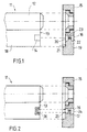
- the locking cylinder shown in Figures 1 and 2 11 has a cylindrical receptacle 12 for one Locking core on, with locking pins, not shown interacts. These locking pins are used in the Introduction of the mechanically suitable key unlocked so that the locking core for actuating the not shown locking nose can be rotated. in this respect the lock cylinder corresponds to a conventional one mechanical locking cylinder and requires no further Explanation.
- a transmitting / receiving element 14 arranged that with a not shown transmitting / receiving unit of the locking cylinder interacts.
- This transmitter / receiver unit can in the Lock cylinder or in a knob on the Locking side facing away from the locking cylinder be arranged.
- Such an arrangement is for example known from DE-U 299 11 353.1 of the applicant which font is expressly referred to here.
- the Training of the transmitter / receiver unit and the means for Therefore, no transmission of the decoding signal is required detailed explanation.
- the signal transmission arrangement has the Anti-pull fitting 15, which via the locking cylinder 11 is mounted, a second transmitting / receiving element 16.
- the arrangement is such that the second transmitting / receiving element 16 in a recess 17 the anti-pull fitting 15 embedded in an area is the fixed web 18 of the lock cylinder 11 covered.
- the second transmitting / receiving element has therefore the same relative position to the key as the transmitting / receiving element arranged directly on the locking cylinder 11 14. Accordingly, the active one or passive transmitter of a key in the inserted Condition the required short distance to contactless signal transmission.
- the protective function the anti-pull fitting 15 still upright is preserved because the area of the locking cylinder of Material, in particular metallic material, is covered.
- the one shown in the drawing Embodiment is the signal cable 22 in the shortest connection between the two in one flight lying transmitting / receiving elements 16, 20 by a Bore 23 out.
- the signal cable in holes or grooves around is guided around the area that lock cylinder 11 covered. This possibility is in the drawing shown in dashed lines.
- the Lock cylinder 11 not with its own transmission / reception element provided on the front end 13.
- the arrangement is such that the transmitting / receiving element 16 on the front 19 of the Pull protection fitting 15 via a signal cable 24 directly in connection with the transmitter / receiver unit of the locking cylinder.
- the signal cable 24 with Contacts 25 on the back 21 of the Pull protection fitting 15 is connected, which in turn with corresponding contacts 26 on the front End face 13 of the lock cylinder 11 cooperate.
- the contacts are designed and dimensioned so that that when installing the anti-pull fitting 15 required connection for signal transmission generated becomes.
- the contacts can be, for example, spring pins or be designed as a plug coupling arrangement.
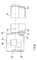
- FIG. 4 shows another embodiment of a Lock cylinder shown.
- the shooting cylinder 11 corresponds to the design of the housing that of Figure 1, and they are the same or equivalent elements with the same reference numerals Mistake.
- the arrangement is such that the locking lug does not have a mechanical key but can be operated via a rotary knob 27.
- the correct decoding signal switches on electrically or electronically operating drive element, Coupling element, locking or unlocking element, so that the actuation of the locking lug via the rotary knob 27 is possible.
- the rotary knob 27 has an outer second Transmit / receive element 28, for example on the Front of the rotary knob 29 is arranged.
- the send / receive element 28 can, as shown, be annular Antenna or formed as a plate-shaped antenna 28 ' be, for example, in the middle range of Front surface 29 of the knob 27 is arranged. This is in the drawing shown in dashed lines.
- the send / receive element 28, 28 ' is in signal connection with a third transmitting / receiving element 30, which on the Lock cylinder 11 facing side 31 of knob 27 is arranged.
- This transmitting / receiving element 30 is preferably formed as an annular antenna whose Radius is dimensioned so that regardless of the Rotary position of the knob 27 always a transmission of the Decoding signal to the transmitting / receiving element 14 am Lock cylinder 11 is possible.
- This arrangement becomes a contactless transmission of the decoding signal from an active or passive transmitter Decoding element via the outer, second transmitting / receiving element 28, a signal cable 32, the inner, third transmission / reception element 30 and the transmission / reception element 14 to the evaluating transmitter / receiver unit of the locking cylinder.
- the transmitting / receiving elements 14, 16, 20, 28, 28 '30 can as coil antennas, for example made of copper wire be formed, preferably in corresponding Plastic elements in recesses of the concerned Components are held. It is also possible to use the antennas to keep in a potting in the recess. The same applies to the contacts 25, 26 at the Embodiment according to FIG. 2.
- the above exemplary embodiments show one Lock cylinder either in combination with a Anti-pull fitting or a knob. It is natural also possible that a knob and an anti-pull fitting can be installed together with the locking cylinder. Instead of a locking core, the Knob 27 in the cylindrical receptacle 12 of the Lock cylinder mounted. The signal transmission takes place then from the outer transmit / receive element 28 via the inside transmitting / receiving element 30 of the knob for Transmitting / receiving element 16 of the anti-pull fitting. There can the signal directly as shown in FIG. 2 or via the further transmission / reception elements 20, 14 to the transmission / reception unit of the lock cylinder are transmitted. Basically, this can also in this embodiment Signal from the knob via a grinding wheel contact to the Lock cylinders are transmitted.
- the in 8 to 10 in particular Antenna arrangement in one by a knob actuable lock cylinder described in more detail.
- the in 8 to 10 has a locking cylinder Cylinder housing 111 in which a knob 112 by one Axis of rotation 113 is rotatably supported.
- the pommel can be in non-rotatable connection brought with a locking lug be operated by a locking bolt.
- the non-rotatable Connection can also be permanent or only through a control signal is generated or released.
- a first antenna 115 On the face 114 of the Cylinder housing 111 is a first antenna 115 arranged. This antenna is in signal connection with a device, not shown, in the cylinder housing, for example an electromechanical clutch, a electrical switch or with another Antenna 124 on the other end of the Cylinder housing.
- the antenna 115 can also have a Device outside the cylinder housing in Signal connection.
- Knob 112 faces the housing End face 116 provided with a second antenna 117.
- This antenna is in signal connection with the first Antenna 115.
- the arrangement is such that the first and second antennas are about the same Have a distance to the axis of rotation 113. This will small transmission distances reached.
- the second antenna can, as shown in Fig. 6, along as a ring antenna the circumference of the end face 116 of the knob be, or just on one sector of the face are located.
- the second antenna 117 can be connected to a Control electronics 118 stand. Then the transferred Signal a control signal for an electrical element in the Be cylinder housing. The signal can also be a Decoding signal from an antenna on the other side of the lock cylinder has been received.
- the second antenna 117 can also be connected to a third Antenna 119 or with a sensor 120, with which a decoding signal is generated.
- the Control electronics can then outside of this knob be arranged.
- Control electronics 118 and a third antenna 119 and / or a sensor 120 are arranged.
- the electronic assemblies only activated when required become.
- the knob is axial is movable to a switching means in an end position to switch, or that with a rotary movement Switching means for activating the control electronics on. In the other axial end position or The knob is turned by a spring in the Rest position kept. Activation can also be done in both End positions occur, and the rest position is a medium one Position is. The electricity consumption can be clear be reduced.
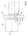
- Fig. 9 is an arrangement for signal transmission shown, in which the cylinder housing by a Protective fitting 121 is protected.
- an antenna 122 on the top 123 of the Security fitting arranged.
- the antenna 122 is in Connection to the lock cylinder, for example a further antenna arrangement 125 or via a Cable connection.
- the antenna on the security fitting can also be arranged on a releasable insert that fits into a appropriate fitting fits. Despite the security fitting the signal can be transmitted wirelessly.
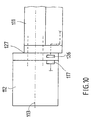
- the first antenna 126 of the lock cylinder 111 in one Intermediate piece 127 arranged on the face 114 of the cylinder housing is attachable.
- the intermediate piece fits the knob 112 with the corresponding one Antenna 117.
- the interacting antennas 126 and 117 as ring antennas along the circumference of the Be formed end face, which is independent of the Allow the angular position of the knob to transmit signals.
- This can be useful for some applications. In particular, this makes it possible to always have the same one Provide raw housing for the locking cylinder, because the choice of the actuating means used independently remains of the design of the housing.
- this intermediate piece 127 conventional slip ring contacts be arranged so that the choice of Signal transmission regardless of the design of the is this housing housing.
- the axis of rotation can also be electronic Switching element, for example, include a clutch. Basically, it will also be possible that the Antenna from the knob along the axis of rotation into that Cylinder housing extends or is formed by this and there cooperates with a fixed antenna.
Landscapes
- Physics & Mathematics (AREA)
- Electromagnetism (AREA)
- Lock And Its Accessories (AREA)
- Emergency Protection Circuit Devices (AREA)
- Arrangements For Transmission Of Measured Signals (AREA)
- Air Bags (AREA)
Abstract
Description
- Fig. 1
- die Seitenansicht eines Schließzylinders mit einem Ziehschutzbeschlag mit einer Signalübertragungsanordnung gemäß der Erfindung in auseinandergezogener Darstellung,
- Fig. 2
- die Seitenansicht eines Schließzylinders mit einem Ziehschutzbeschlag gemäß einer anderen Ausführungsform der Erfindung in auseinandergezogener Darstellung,
- Fig. 3
- die Vorderansicht auf einen Ziehschutzbeschlag mit einer Signalübertragungsanordnung gemäß Fig. 1 oder Fig. 2,
- Fig. 4
- die Seitenansicht eines Schließzylinders mit einem Drehknauf und einer Signalübertragungsanordnung gemäß der Erfindung,
- Fig. 5
- die Vorderansicht des Drehknaufs gemäß Fig. 4,
- Fig. 6
- die Draufsicht auf die dem Schließzylinder zugekehrte Seite des Drehknaufs gemäß Fig. 4,
- Fig. 7
- die Draufsicht auf einen Schließzylinder,
- Fig. 8
- die Seitenansicht eines Schließzylinders mit einem Knauf und einer Signalübertragungsanordnung gemäß der Erfindung,
- Fig. 9
- die Seitenansicht auf einen Schließzylinder und einem Knauf mit Ziehschutzbeschlag gemäß der Erfindung und
- Fig. 10
- die Seitenansicht eines Schließzylinders gemäß einer weiteren Ausführungsform der Erfindung.
Claims (20)
- Anordnung zur Übertragung des Dekodierungssignals für einen durch einen Ziehschutzbeschlag (15) geschützten Schließzylinder (11) mit einer Sende-/Empfangseinheit zum kontaktlosen Empfangen des Dekodierungssignals, die wenigstens ein erstes Sende-/Empfangselement (14) aufweist, das im vorderen Stirnflächenbereich (13) des Schließzylinders angeordnet ist, dadurch gekennzeichnet, daß ein zweites Sende-/Empfangselement (16) auf der Vorderseite (19) des Ziehschutzbeschlages angeordnet ist, das in Signalverbindung mit einem dritten Sende/Empfangselement (20) auf der Rückseite des Ziehschutzbeschlages steht, das in Signalverbindung mit dem ersten Sende-/Empfangselement (14) auf der Stirnseite des Schließzylinders steht.
- Anordnung zur Übertragung des Dekodierungssignals für einen durch einen Ziehschutzbeschlag (15) geschützten Schließzylinder (11) mit einer Sende-/Empfangseinheit (16) zum kontaktlosen Empfangen des Dekodierungssignals, die wenigstens ein Sende-/Empfangselement aufweist, dadurch gekennzeichnet, daß das Sende-/Empfangselement auf der Vorderseite (19) des Ziehschutzbeschlages angeordnet ist, das in einer Signalverbindung (24, 25, 26) mit der Sende-/Empfangseinheit des Schließzylinders steht.
- Anordnung nach einem der Ansprüche 1 oder 2, dadurch gekennzeichnet, daß das Sende-/Empfangselement auf der Vorderseite (19) des Ziehschutzbeschlages (15) zumindest teilweise in dem Bereich angeordnet ist, der den Schließzylinder überdeckt.
- Anordnung nach einem der Ansprüche 1 bis 3, dadurch gekennzeichnet, daß das Sende-/Empfangselement auf der Vorderseite des Ziehschutzbeschlages in dem den Schließzylinder zumindest teilweise umgebenden Bereich angeordnet ist.
- Anordnung nach einem der Ansprüche 1 bis 4, dadurch gekennzeichnet, daß die Signalübertragung zum Sende/Empfangselement auf der Vorderseite des Ziehschutzbeschlages durch ein Signalkabel (22) erfolgt.
- Anordnung nach Anspruch 5, dadurch gekennzeichnet, daß das Kabel durch eine Bohrung (23) oder Nut im Ziehschutzbeschlag geführt ist, die außerhalb des Bereiches des Ziehschutzbeschlages (15) liegt, der den Schließzylinder überdeckt.
- Anordnung nach einem der Ansprüche 1 bis 6, dadurch gekennzeichnet, daß der Schließzylinder mit einem Knauf betätigbar ist, der ein äußeres zweites Sende/Empfangselement (28, 28') aufweist, das in Signalverbindung mit einem dritten Sende-/Empfangselement (30) auf der dem Ziehschutzbeschlag (15) zugekehrten Seite (31) des Knaufs steht, das in Signalverbindung mit dem Sende-/Empfangselement (16) auf der Vorderseite des Ziehschutzbeschlages steht.
- Anordnung zur Übertragung des Dekodierungssignals für einen mit einem Knauf (27) zu betätigenden Schließzylinder (11) mit einer Sende-/Empfangseinheit zum kontaktlosen Empfangen des Dekodierungssignals, die wenigstens ein erstes Sende-/Empfangselement (14) aufweist, das im vorderen Stirnflächenbereich (13) des Schließzylinders angeordnet ist, dadurch gekennzeichnet, daß ein zweites Sende-/Empfangselement (28, 28') auf dem Knauf angeordnet ist, das in Signalverbindung mit einem dritten Sende-/Empfangselement (30) auf der dem Schließzylinder zugekehrten Seite (31) des Knaufs steht, das in Signalverbindung mit dem ersten Sende/Empfangselement (14) auf der Stirnseite des Schließzylinders steht.
- Anordnung zur Übertragung des Dekodierungssignals für einen mit einem Knauf zu betätigenden Schließzylinder mit einer Sende-/Empfangseinheit zum kontaktlosen Empfangen eines Dekodierungssignals, die wenigstens ein Sende/Empfangselement aufweist, dadurch gekennzeichnet, daß das Sende-/Empfangselement auf dem Knauf angeordnet ist, das in einer Signalverbindung mit der Sende/Empfangseinheit des Schließzylinders steht.
- Anordnung nach einem der Ansprüche 1 bis 9, dadurch gekennzeichnet, daß die Sende-/Empfangseinheit mit einem passiven Transponder auf einem Decodierelement, insbesondere auf einem Schlüssel oder einer Chipkarte, zusammenwirkt.
- Anordnung zur Übertragung eines Signals für einen mit einem um eine Drehachse (13) drehbaren Knauf (12) zu betätigenden Schließzylinder mit wenigstens einer ersten Antenne (15, 22, 26) an, in, vor oder auf dem feststehenden Gehäuse des Schließzylinders und mit wenigstens einer zweiten Antenne (17) an, in, vor oder auf dem Knauf, die in einer Signalverbindung mit der ersten Antenne des Schließzylinders steht.
- Anordnung nach Anspruch 11, dadurch gekennzeichnet, daß die erste Antenne im vorderen Stirnflächenbereich (14) des Gehäuses des Schließzylinders und die zweite Antenne (17) auf der dem Schließzylinder zugekehrten Stirnfläche (16) des Knaufs (12) angeordnet ist.
- Anordnung nach einem der Ansprüche 11 bis 12, dadurch gekennzeichnet, daß die erste Antenne (22) auf einem Schutzbeschlag (21) angeordnet ist.
- Anordnung nach einem der Ansprüche 11 bis 13, dadurch gekennzeichnet, daß in dem Knauf an oder über der mit diesem drehenden Drehachse eine Antenne angeordnet ist und an oder über dem in das Gehäuse des Schließzylinders hineinragenden Abschnitt der Drehachse eine Antenne relativ zur Drehachse drehbar fest im Gehäuse angeordnet ist, und daß die Drehachse zumindest zwischen diesen Antennen aus einem magnetisierbaren Material besteht.
- Anordnung nach einem der Ansprüche 11 bis 14, dadurch gekennzeichnet, daß sich die Antenne vom Knauf entlang der Drehachse bis in das Zylindergehäuse erstreckt oder durch diese gebildet wird und dort mit einer feststehenden Antenne zusammenwirkt.
- Knauf für eine Anordnung und einen Schließzylinder insbesondere gemäß einem oder mehreren der vorhergehenden Ansprüche, dadurch gekennzeichnet, daß auf, vor, an oder in dem Knauf eine Antenne vorhanden ist, die in eine Signalverbindung mit einer Antenne des Schließzylinders bringbar ist.
- Ziehschutzbeschlag für eine Anordnung mit einem Schließzylinder und/oder Knauf insbesondere gemäß einem oder mehreren der vorhergehenden Ansprüche, dadurch gekennzeichnet, daß vor dem Ziehschutzbeschlag wenigstens eine Antenne vorhanden ist, die in eine Signalverbindung mit einer Antenne des Kaufs oder einer Antenne eines Schlüssels bringbar ist.
- Ziehschutzbeschlag nach Anspruch 17, dadurch gekennzeichnet, daß die Antenne vor dem Ziehschutzbeschlag in unmittelbarer Signalverbindung mit der Sende- und Empfangseinheit des Schließzylinders steht.
- Ziehschutzbeschlag nach Anspruch 17, dadurch gekennzeichnet, daß hinter dem Ziehschutzbeschlag eine Antenne angeordnet ist, die in eine Signalverbindung mit einer Antenne des Schließzylinders bringbar ist.
- Ziehschutzbeschlag nach einem der Ansprüche 17 bis 19, dadurch gekennzeichnet, daß die Antenne des Ziehschutzbeschlags in einem Einsatz angeordnet ist, der in den Ziehschutzbeschlag einsetzbar ist.
Applications Claiming Priority (4)
| Application Number | Priority Date | Filing Date | Title |
|---|---|---|---|
| DE10035932 | 2000-07-21 | ||
| DE2000135932 DE10035932C1 (de) | 2000-07-21 | 2000-07-21 | Schliesszylinder mit kontaktloser Übertragung eines Dekodierungssignals |
| DE20102853U | 2001-02-16 | ||
| DE20102853U DE20102853U1 (de) | 2000-07-21 | 2001-02-16 | Schließzylinder mit kontaktloser Übertragung eines Signals |
Publications (3)
| Publication Number | Publication Date |
|---|---|
| EP1174572A2 true EP1174572A2 (de) | 2002-01-23 |
| EP1174572A3 EP1174572A3 (de) | 2004-03-17 |
| EP1174572B1 EP1174572B1 (de) | 2007-10-10 |
Family
ID=26006494
Family Applications (1)
| Application Number | Title | Priority Date | Filing Date |
|---|---|---|---|
| EP01117887A Expired - Lifetime EP1174572B1 (de) | 2000-07-21 | 2001-07-23 | Schliesszylinder mit einer Anordnung zum kontaktlosen Übertragen eines Signals |
Country Status (3)
| Country | Link |
|---|---|
| EP (1) | EP1174572B1 (de) |
| AT (1) | ATE375425T1 (de) |
| DE (1) | DE50113103D1 (de) |
Cited By (12)
| Publication number | Priority date | Publication date | Assignee | Title |
|---|---|---|---|---|
| EP1739631A1 (de) * | 2005-06-24 | 2007-01-03 | BUGA Technologies GmbH | Modularer elektromechanischer Schliesszylinder |
| EP2214141A1 (de) * | 2003-10-01 | 2010-08-04 | Palladio Systeme GmbH | Verfahren zur Erhöhung der Stör- und Übertragungssicherheit bei der Bereitstellung von Daten mittels drahtloser, insbesondere hochfrequenter Netzwerke zur Steuerung, Programmierung, Überwachung und Auswertung von Schließanlagen mit elektromechanischer Betätigung |
| US7845202B2 (en) | 2006-09-22 | 2010-12-07 | Assa Abloy Ab | Interchangeable electromechanical lock core |
| US7874190B2 (en) | 2003-06-23 | 2011-01-25 | Assa Abloy Ab | Electromechanical lock cylinder |
| WO2014101911A1 (de) * | 2012-12-17 | 2014-07-03 | Assa Abloy Sicherheitstechnik Gmbh | Schliesszylinder, insbesondere doppelschliesszylinder |
| EP2708681A3 (de) * | 2012-09-12 | 2017-10-18 | Aug. Winkhaus GmbH & Co. KG | Schließzylinder für einen elektronischen Schlüssel |
| EP2453085B1 (de) | 2010-11-10 | 2017-12-06 | BKS GmbH | Schliesseinrichtung |
| USD891901S1 (en) | 2019-04-05 | 2020-08-04 | Dormakaba Usa Inc. | Knob |
| US11339589B2 (en) | 2018-04-13 | 2022-05-24 | Dormakaba Usa Inc. | Electro-mechanical lock core |
| US11466473B2 (en) | 2018-04-13 | 2022-10-11 | Dormakaba Usa Inc | Electro-mechanical lock core |
| US11913254B2 (en) | 2017-09-08 | 2024-02-27 | dormakaba USA, Inc. | Electro-mechanical lock core |
| US11933076B2 (en) | 2016-10-19 | 2024-03-19 | Dormakaba Usa Inc. | Electro-mechanical lock core |
Citations (2)
| Publication number | Priority date | Publication date | Assignee | Title |
|---|---|---|---|---|
| EP0187363B1 (de) | 1985-01-08 | 1988-07-27 | BKS GmbH | Mechanisch und nichtmechanisch codierter Schlüssel sowie dadurch zu betätigendes Schloss |
| DE19930054A1 (de) | 1999-06-30 | 2001-01-18 | Buga Schliessysteme Ag | Elektromechanisches Schließsystem |
Family Cites Families (4)
| Publication number | Priority date | Publication date | Assignee | Title |
|---|---|---|---|---|
| DE4207161A1 (de) * | 1992-03-06 | 1993-09-09 | Winkhaus Fa August | Elektronischer schliesszylinder |
| DE4314903A1 (de) * | 1993-05-05 | 1994-11-10 | Winkhaus Fa August | Schloßanordnung |
| EP0730073A2 (de) * | 1995-03-03 | 1996-09-04 | Kaba Schliesssysteme AG | Schliessvorrichtung mit elektrischer Verriegelung |
| DE19861400B4 (de) * | 1997-11-07 | 2013-08-01 | Simonsvoss Technologies Ag | Schließzylinder |
-
2001
- 2001-07-23 DE DE50113103T patent/DE50113103D1/de not_active Expired - Lifetime
- 2001-07-23 AT AT01117887T patent/ATE375425T1/de not_active IP Right Cessation
- 2001-07-23 EP EP01117887A patent/EP1174572B1/de not_active Expired - Lifetime
Patent Citations (2)
| Publication number | Priority date | Publication date | Assignee | Title |
|---|---|---|---|---|
| EP0187363B1 (de) | 1985-01-08 | 1988-07-27 | BKS GmbH | Mechanisch und nichtmechanisch codierter Schlüssel sowie dadurch zu betätigendes Schloss |
| DE19930054A1 (de) | 1999-06-30 | 2001-01-18 | Buga Schliessysteme Ag | Elektromechanisches Schließsystem |
Cited By (20)
| Publication number | Priority date | Publication date | Assignee | Title |
|---|---|---|---|---|
| US7874190B2 (en) | 2003-06-23 | 2011-01-25 | Assa Abloy Ab | Electromechanical lock cylinder |
| EP2214141A1 (de) * | 2003-10-01 | 2010-08-04 | Palladio Systeme GmbH | Verfahren zur Erhöhung der Stör- und Übertragungssicherheit bei der Bereitstellung von Daten mittels drahtloser, insbesondere hochfrequenter Netzwerke zur Steuerung, Programmierung, Überwachung und Auswertung von Schließanlagen mit elektromechanischer Betätigung |
| EP1739631A1 (de) * | 2005-06-24 | 2007-01-03 | BUGA Technologies GmbH | Modularer elektromechanischer Schliesszylinder |
| US8028553B2 (en) | 2005-06-24 | 2011-10-04 | Assa Abloy Ab | Modular electromechanical lock cylinder |
| US7845202B2 (en) | 2006-09-22 | 2010-12-07 | Assa Abloy Ab | Interchangeable electromechanical lock core |
| EP2453085B1 (de) | 2010-11-10 | 2017-12-06 | BKS GmbH | Schliesseinrichtung |
| EP2708681A3 (de) * | 2012-09-12 | 2017-10-18 | Aug. Winkhaus GmbH & Co. KG | Schließzylinder für einen elektronischen Schlüssel |
| WO2014101911A1 (de) * | 2012-12-17 | 2014-07-03 | Assa Abloy Sicherheitstechnik Gmbh | Schliesszylinder, insbesondere doppelschliesszylinder |
| US11933076B2 (en) | 2016-10-19 | 2024-03-19 | Dormakaba Usa Inc. | Electro-mechanical lock core |
| US11913254B2 (en) | 2017-09-08 | 2024-02-27 | dormakaba USA, Inc. | Electro-mechanical lock core |
| US11339589B2 (en) | 2018-04-13 | 2022-05-24 | Dormakaba Usa Inc. | Electro-mechanical lock core |
| US11447980B2 (en) | 2018-04-13 | 2022-09-20 | Dormakaba Usa Inc. | Puller tool |
| US11466473B2 (en) | 2018-04-13 | 2022-10-11 | Dormakaba Usa Inc | Electro-mechanical lock core |
| US12031357B2 (en) | 2018-04-13 | 2024-07-09 | Dormakaba Usa Inc. | Electro-mechanical lock core |
| US12071788B2 (en) | 2018-04-13 | 2024-08-27 | Dormakaba Usa Inc. | Electro-mechanical lock core |
| US12435546B2 (en) | 2018-04-13 | 2025-10-07 | Dormakaba Usa Inc. | Electro-mechanical lock core |
| USD937655S1 (en) | 2019-04-05 | 2021-12-07 | Dormakaba Usa Inc. | Knob |
| USD965407S1 (en) | 2019-04-05 | 2022-10-04 | Dormakaba Usa Inc | Knob |
| USD926018S1 (en) | 2019-04-05 | 2021-07-27 | Dormakaba Usa Inc. | Knob |
| USD891901S1 (en) | 2019-04-05 | 2020-08-04 | Dormakaba Usa Inc. | Knob |
Also Published As
| Publication number | Publication date |
|---|---|
| ATE375425T1 (de) | 2007-10-15 |
| EP1174572B1 (de) | 2007-10-10 |
| DE50113103D1 (de) | 2007-11-22 |
| EP1174572A3 (de) | 2004-03-17 |
Similar Documents
| Publication | Publication Date | Title |
|---|---|---|
| DE19861400B4 (de) | Schließzylinder | |
| EP0976896B1 (de) | Schliesssystem | |
| DE19854879C1 (de) | Verschlußeinrichtung für Türen mit integrierter Antenne zur Funkfernbedienung | |
| DE69501206T2 (de) | Sicherheitssystem für fahrzeuge | |
| EP1174572B1 (de) | Schliesszylinder mit einer Anordnung zum kontaktlosen Übertragen eines Signals | |
| DE19930054C5 (de) | Elektromechanisches Schließsystem | |
| EP1256671B1 (de) | Rosette für einen zugeordneten Schliesszylinder | |
| EP0999328A1 (de) | Schliesszylinder | |
| EP0978611A2 (de) | Schliesssystem | |
| DE102004046778B4 (de) | Schließzylinder mit erhöhter Eingriffssicherheit | |
| EP0224607A1 (de) | Schliessvorrichtung mit elektronischem Identifizierungssystem | |
| EP3795786B9 (de) | Glasstürschloss mit autarkem funkmodul | |
| DE10035932C1 (de) | Schliesszylinder mit kontaktloser Übertragung eines Dekodierungssignals | |
| EP1736622B1 (de) | Schließzylinder | |
| EP0882858B1 (de) | Schliesszylinder mit elektromagnetisch betätigbarem Sperrstift | |
| DE10252025A1 (de) | Schloß | |
| DE3521822A1 (de) | Sender- und empfaengergesteuerte schliesseinrichtung | |
| DE10164831B4 (de) | Programmierbarer elektromechanischer Schließzylinder | |
| EP1580354B1 (de) | Beschlag | |
| EP2998470B1 (de) | Beschlag für eine gebäudetür | |
| EP1716544B1 (de) | Profilschliesszylinder zur erhöhung der stör- und übertragungssicherheit bei der bereitstellung von daten mittels drahtloser, insbesondere hochfrequenter netzwerke zur steuerung, programmierung, überwachung und auswertung von schliessanlagen mit elektromechanischer betätigung | |
| EP2998465B1 (de) | Beschlag für eine gebäudetür und ein verfahren hierfür | |
| DE29911356U1 (de) | Antennenanordnung für ein durch Funksignal betätigbares Schließsystem | |
| DE20207283U1 (de) | Türschloss | |
| DE10131280A1 (de) | Wendeschlüssel |
Legal Events
| Date | Code | Title | Description |
|---|---|---|---|
| PUAI | Public reference made under article 153(3) epc to a published international application that has entered the european phase |
Free format text: ORIGINAL CODE: 0009012 |
|
| AK | Designated contracting states |
Kind code of ref document: A2 Designated state(s): AT BE CH CY DE DK ES FI FR GB GR IE IT LI LU MC NL PT SE TR |
|
| AX | Request for extension of the european patent |
Free format text: AL;LT;LV;MK;RO;SI |
|
| PUAL | Search report despatched |
Free format text: ORIGINAL CODE: 0009013 |
|
| AK | Designated contracting states |
Kind code of ref document: A3 Designated state(s): AT BE CH CY DE DK ES FI FR GB GR IE IT LI LU MC NL PT SE TR |
|
| AX | Request for extension of the european patent |
Extension state: AL LT LV MK RO SI |
|
| 17P | Request for examination filed |
Effective date: 20040906 |
|
| RAP1 | Party data changed (applicant data changed or rights of an application transferred) |
Owner name: BUGA TECHNOLOGIES GMBH |
|
| AKX | Designation fees paid |
Designated state(s): AT BE CH CY DE DK ES FI FR GB GR IE IT LI LU MC NL PT SE TR |
|
| 17Q | First examination report despatched |
Effective date: 20041227 |
|
| GRAP | Despatch of communication of intention to grant a patent |
Free format text: ORIGINAL CODE: EPIDOSNIGR1 |
|
| GRAS | Grant fee paid |
Free format text: ORIGINAL CODE: EPIDOSNIGR3 |
|
| RAP1 | Party data changed (applicant data changed or rights of an application transferred) |
Owner name: HID GMBH |
|
| GRAA | (expected) grant |
Free format text: ORIGINAL CODE: 0009210 |
|
| AK | Designated contracting states |
Kind code of ref document: B1 Designated state(s): AT BE CH CY DE DK ES FI FR GB GR IE IT LI LU MC NL PT SE TR |
|
| REG | Reference to a national code |
Ref country code: GB Ref legal event code: FG4D Free format text: NOT ENGLISH |
|
| REG | Reference to a national code |
Ref country code: CH Ref legal event code: EP |
|
| REG | Reference to a national code |
Ref country code: IE Ref legal event code: FG4D Free format text: LANGUAGE OF EP DOCUMENT: GERMAN |
|
| REF | Corresponds to: |
Ref document number: 50113103 Country of ref document: DE Date of ref document: 20071122 Kind code of ref document: P |
|
| GBT | Gb: translation of ep patent filed (gb section 77(6)(a)/1977) |
Effective date: 20080113 |
|
| PG25 | Lapsed in a contracting state [announced via postgrant information from national office to epo] |
Ref country code: SE Free format text: LAPSE BECAUSE OF FAILURE TO SUBMIT A TRANSLATION OF THE DESCRIPTION OR TO PAY THE FEE WITHIN THE PRESCRIBED TIME-LIMIT Effective date: 20080110 Ref country code: ES Free format text: LAPSE BECAUSE OF FAILURE TO SUBMIT A TRANSLATION OF THE DESCRIPTION OR TO PAY THE FEE WITHIN THE PRESCRIBED TIME-LIMIT Effective date: 20080121 |
|
| PG25 | Lapsed in a contracting state [announced via postgrant information from national office to epo] |
Ref country code: PT Free format text: LAPSE BECAUSE OF FAILURE TO SUBMIT A TRANSLATION OF THE DESCRIPTION OR TO PAY THE FEE WITHIN THE PRESCRIBED TIME-LIMIT Effective date: 20080310 |
|
| REG | Reference to a national code |
Ref country code: IE Ref legal event code: FD4D |
|
| ET | Fr: translation filed | ||
| PG25 | Lapsed in a contracting state [announced via postgrant information from national office to epo] |
Ref country code: DK Free format text: LAPSE BECAUSE OF FAILURE TO SUBMIT A TRANSLATION OF THE DESCRIPTION OR TO PAY THE FEE WITHIN THE PRESCRIBED TIME-LIMIT Effective date: 20071010 |
|
| PLBE | No opposition filed within time limit |
Free format text: ORIGINAL CODE: 0009261 |
|
| STAA | Information on the status of an ep patent application or granted ep patent |
Free format text: STATUS: NO OPPOSITION FILED WITHIN TIME LIMIT |
|
| 26N | No opposition filed |
Effective date: 20080711 |
|
| PG25 | Lapsed in a contracting state [announced via postgrant information from national office to epo] |
Ref country code: IE Free format text: LAPSE BECAUSE OF FAILURE TO SUBMIT A TRANSLATION OF THE DESCRIPTION OR TO PAY THE FEE WITHIN THE PRESCRIBED TIME-LIMIT Effective date: 20071010 |
|
| PG25 | Lapsed in a contracting state [announced via postgrant information from national office to epo] |
Ref country code: GR Free format text: LAPSE BECAUSE OF FAILURE TO SUBMIT A TRANSLATION OF THE DESCRIPTION OR TO PAY THE FEE WITHIN THE PRESCRIBED TIME-LIMIT Effective date: 20080111 |
|
| PG25 | Lapsed in a contracting state [announced via postgrant information from national office to epo] |
Ref country code: FI Free format text: LAPSE BECAUSE OF FAILURE TO SUBMIT A TRANSLATION OF THE DESCRIPTION OR TO PAY THE FEE WITHIN THE PRESCRIBED TIME-LIMIT Effective date: 20071010 |
|
| REG | Reference to a national code |
Ref country code: CH Ref legal event code: PL |
|
| PG25 | Lapsed in a contracting state [announced via postgrant information from national office to epo] |
Ref country code: MC Free format text: LAPSE BECAUSE OF NON-PAYMENT OF DUE FEES Effective date: 20080731 |
|
| PG25 | Lapsed in a contracting state [announced via postgrant information from national office to epo] |
Ref country code: LI Free format text: LAPSE BECAUSE OF NON-PAYMENT OF DUE FEES Effective date: 20080731 Ref country code: CH Free format text: LAPSE BECAUSE OF NON-PAYMENT OF DUE FEES Effective date: 20080731 |
|
| PG25 | Lapsed in a contracting state [announced via postgrant information from national office to epo] |
Ref country code: CY Free format text: LAPSE BECAUSE OF FAILURE TO SUBMIT A TRANSLATION OF THE DESCRIPTION OR TO PAY THE FEE WITHIN THE PRESCRIBED TIME-LIMIT Effective date: 20071010 |
|
| NLS | Nl: assignments of ep-patents |
Owner name: ASSA ABLOY AB Effective date: 20090721 |
|
| REG | Reference to a national code |
Ref country code: GB Ref legal event code: 732E Free format text: REGISTERED BETWEEN 20090917 AND 20090923 |
|
| PG25 | Lapsed in a contracting state [announced via postgrant information from national office to epo] |
Ref country code: AT Free format text: LAPSE BECAUSE OF NON-PAYMENT OF DUE FEES Effective date: 20080723 |
|
| PG25 | Lapsed in a contracting state [announced via postgrant information from national office to epo] |
Ref country code: BE Free format text: LAPSE BECAUSE OF NON-PAYMENT OF DUE FEES Effective date: 20080731 Ref country code: LU Free format text: LAPSE BECAUSE OF NON-PAYMENT OF DUE FEES Effective date: 20080723 |
|
| PG25 | Lapsed in a contracting state [announced via postgrant information from national office to epo] |
Ref country code: TR Free format text: LAPSE BECAUSE OF FAILURE TO SUBMIT A TRANSLATION OF THE DESCRIPTION OR TO PAY THE FEE WITHIN THE PRESCRIBED TIME-LIMIT Effective date: 20071010 |
|
| REG | Reference to a national code |
Ref country code: FR Ref legal event code: TP Owner name: ASSA ABLOY AB, SE Effective date: 20130925 |
|
| REG | Reference to a national code |
Ref country code: FR Ref legal event code: PLFP Year of fee payment: 16 |
|
| REG | Reference to a national code |
Ref country code: FR Ref legal event code: PLFP Year of fee payment: 17 |
|
| REG | Reference to a national code |
Ref country code: FR Ref legal event code: PLFP Year of fee payment: 18 |
|
| PGFP | Annual fee paid to national office [announced via postgrant information from national office to epo] |
Ref country code: FR Payment date: 20190626 Year of fee payment: 19 Ref country code: NL Payment date: 20190712 Year of fee payment: 19 |
|
| PGFP | Annual fee paid to national office [announced via postgrant information from national office to epo] |
Ref country code: DE Payment date: 20190710 Year of fee payment: 19 Ref country code: IT Payment date: 20190719 Year of fee payment: 19 |
|
| PGFP | Annual fee paid to national office [announced via postgrant information from national office to epo] |
Ref country code: GB Payment date: 20190717 Year of fee payment: 19 |
|
| REG | Reference to a national code |
Ref country code: DE Ref legal event code: R119 Ref document number: 50113103 Country of ref document: DE |
|
| REG | Reference to a national code |
Ref country code: NL Ref legal event code: MM Effective date: 20200801 |
|
| GBPC | Gb: european patent ceased through non-payment of renewal fee |
Effective date: 20200723 |
|
| PG25 | Lapsed in a contracting state [announced via postgrant information from national office to epo] |
Ref country code: FR Free format text: LAPSE BECAUSE OF NON-PAYMENT OF DUE FEES Effective date: 20200731 Ref country code: GB Free format text: LAPSE BECAUSE OF NON-PAYMENT OF DUE FEES Effective date: 20200723 Ref country code: NL Free format text: LAPSE BECAUSE OF NON-PAYMENT OF DUE FEES Effective date: 20200801 |
|
| PG25 | Lapsed in a contracting state [announced via postgrant information from national office to epo] |
Ref country code: DE Free format text: LAPSE BECAUSE OF NON-PAYMENT OF DUE FEES Effective date: 20210202 |
|
| PG25 | Lapsed in a contracting state [announced via postgrant information from national office to epo] |
Ref country code: IT Free format text: LAPSE BECAUSE OF NON-PAYMENT OF DUE FEES Effective date: 20200723 |