EP1174573B1 - Verriegelungsvorrichtung mit einstellbarem Riegel und Verriegelungsschraube für Schiebeflügel - Google Patents
Verriegelungsvorrichtung mit einstellbarem Riegel und Verriegelungsschraube für Schiebeflügel Download PDFInfo
- Publication number
- EP1174573B1 EP1174573B1 EP01401792A EP01401792A EP1174573B1 EP 1174573 B1 EP1174573 B1 EP 1174573B1 EP 01401792 A EP01401792 A EP 01401792A EP 01401792 A EP01401792 A EP 01401792A EP 1174573 B1 EP1174573 B1 EP 1174573B1
- Authority
- EP
- European Patent Office
- Prior art keywords
- bolt
- screw
- locking
- slot
- locking device
- Prior art date
- Legal status (The legal status is an assumption and is not a legal conclusion. Google has not performed a legal analysis and makes no representation as to the accuracy of the status listed.)
- Expired - Lifetime
Links
- 230000000295 complement effect Effects 0.000 claims description 12
- 230000000903 blocking effect Effects 0.000 description 3
- 210000002445 nipple Anatomy 0.000 description 3
- 101100536354 Drosophila melanogaster tant gene Proteins 0.000 description 1
- 238000004519 manufacturing process Methods 0.000 description 1
- 238000010079 rubber tapping Methods 0.000 description 1
Images
Classifications
-
- E—FIXED CONSTRUCTIONS
- E05—LOCKS; KEYS; WINDOW OR DOOR FITTINGS; SAFES
- E05B—LOCKS; ACCESSORIES THEREFOR; HANDCUFFS
- E05B65/00—Locks or fastenings for special use
- E05B65/08—Locks or fastenings for special use for sliding wings
- E05B65/087—Locks or fastenings for special use for sliding wings the bolts sliding parallel to the wings
-
- E—FIXED CONSTRUCTIONS
- E05—LOCKS; KEYS; WINDOW OR DOOR FITTINGS; SAFES
- E05B—LOCKS; ACCESSORIES THEREFOR; HANDCUFFS
- E05B63/00—Locks or fastenings with special structural characteristics
- E05B63/06—Locks or fastenings with special structural characteristics with lengthwise-adjustable bolts ; with adjustable backset, i.e. distance from door edge
-
- E—FIXED CONSTRUCTIONS
- E05—LOCKS; KEYS; WINDOW OR DOOR FITTINGS; SAFES
- E05B—LOCKS; ACCESSORIES THEREFOR; HANDCUFFS
- E05B9/00—Lock casings or latch-mechanism casings ; Fastening locks or fasteners or parts thereof to the wing
- E05B9/08—Fastening locks or fasteners or parts thereof, e.g. the casings of latch-bolt locks or cylinder locks to the wing
Definitions
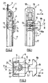
- FIGS. 1 to 3 attached illustrate the adjustable bolt fitting described in the application of the aforementioned patent.
- the fitting 1 with adjustable bolt for sliding door 3, window or the like comprises a bolt holder 4 having at least one slot 5 adapted to receive the tail 6 of a bolt 7 carrying hooks 8a, 8b.
- the bolt holder 4 is adapted to slide in the transverse direction 9 slot 5 to bring the hook 8a, 8b of the bolt 7 engaged with a keeper (not shown) of the frame and to release the hook from the keeper.
- the bolt 7 is adapted to slide in the longitudinal direction 11 of the slot 5 for allow adjustment of the bolt 7 relative to the strike.
- the fitting 1 comprises a housing 17 comprising a plate exterior 18.
- the fitting 1 is fixed at each end by means of a attachment 19 of any type to the wall 20 on the inner side of the opening 3. This structure is not mandatory.
- the tail 6 of the bolt 7 has a light 21 which is heard in the direction longitudinal 11 of the slot 5, and the screw 16 is adapted to bear on the edges 22, 23 of light 21.
- the longitudinal edges 22, 23 of the lumen 21 have teeth 25 in protruding towards the opposite edges 23, 22.
- the axis 13 of the tapped hole 12 is offset from the median axis 24 of the lumen 21 and the tail 6 of the bolt 7, from a distance A.
- This tool can be, for example, a Phillips screwdriver whose end has teeth which can engage the teeth 25 to move the bolt.
- the above device thus has many advantages.
- the purpose of the present invention is to describe and protect these improvements.
- the fitting comprises a member complementary to the screw blocking cooperating with the tail of the bolt to prevent the sliding of this bolt in the slot of the bolt holder, this complementary member being accessible from the outside the housing of the fitting on the same side as the locking screw.
- the tail of the bolt has at least one light which is heard in the longitudinal direction of the slot, the screw being adapted to bear on at least one edges of the light.
- the complementary member consists of a nipple carried by the end of the screw adapted to bear on at least one of the edges light, said stud being adapted to engage with one of said edges.
- At least one of said light edges have teeth forming protruding towards the other edge.
- the nipple is adapted to come into engagement with the teeth during tightening of said screw.
- the complementary member is a second screw screwed into a tapped hole made in the bolt holder parallel to the tapped hole dan which is engaged said locking screw, the end of this second screw taking support on one of the longitudinal edges of the bolt tail, said longitudinal edge projecting into the tapped hole into which said second screw is screwed.
- the bolt holder includes a member complementary to the locking screw 16 cooperating with the tail of the bolt to prevent the sliding of this bolt in the slot 5 of the bolt holder 4.
- the complementary member is constituted by a stud carried by the end of the screw 16 adapted to bear on the minus one of the edges of the light 21.
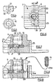
- This stud 30 is adapted to come into engagement with one of said edges, as shown by the Figures 6 and 7.
- the stud 30 is in fact adapted to come in engagement with the teeth 25 of the lumen 21, when the screw 16 is tightened.
- the outer surface of the tail 6 of the bolt is striated.
- the stud 30 extends along the axis 31 of the screw 6 and the axis of the tapped hole 32 into which the screw 16 is screwed is offset by relative to the median axis 33 of the lumen 21 of a distance A sufficient to allow to the nipple to engage and engage between two teeth 25 of the lumen 21, during the tightening the screw 16.
- the stud 30 has a frustoconical shape narrowed at its free end. This arrangement facilitates engagement between the teeth 25 of the lumen 21.
- the stud 30 of the screw 16 is offset from the axis of the screw by a distance equal to A.
- the tapping axis of screw 16 is not offset from the median axis of light 21.
- the complementary member is a second screw 34 screwed into a tapped hole 35 made in the bolt holder 4 parallel to the threaded hole 32 in which said locking screw 16 is engaged.
- the second screw 34 has one end pointed whose lateral surface bears on the longitudinal edge 6a so as to come engaged with it due to the tightening of the second screw 34.
Landscapes
- Connection Of Plates (AREA)
- Wing Frames And Configurations (AREA)
- Hinges (AREA)
- Closing And Opening Devices For Wings, And Checks For Wings (AREA)
- Details Of Spanners, Wrenches, And Screw Drivers And Accessories (AREA)
- Hinge Accessories (AREA)
- Devices For Conveying Motion By Means Of Endless Flexible Members (AREA)
- Fittings On The Vehicle Exterior For Carrying Loads, And Devices For Holding Or Mounting Articles (AREA)
- Mechanical Pencils And Projecting And Retracting Systems Therefor, And Multi-System Writing Instruments (AREA)
- Forms Removed On Construction Sites Or Auxiliary Members Thereof (AREA)
- Pens And Brushes (AREA)
- Mutual Connection Of Rods And Tubes (AREA)
- Door And Window Frames Mounted To Openings (AREA)
Claims (7)
- Beschlag (1) mit einstellbarem Riegel (7) für Schiebeflügel (3) von Tür, Fenster oder dergleichen, mit einem Riegelträger (4), der mindestens einen Schlitz (5) aufweist für die Aufnahme des Schaftes (6) eines mindestens einen Haken (8) tragenden Riegels (7), wobei der Riegelträger (4) in der Querrichtung (9) des Schlitzes (5) verschiebbar ist, um den Riegelhaken (7) in Eingriff mit einem Schließblech am Stockrahmen zu bringen und um den Haken von dem Schließblech freizugeben, wobei der Riegel (7) in der Längsrichtung (11) des Schlitzes (5) verschiebbar ist, um die Einstellung des Riegels (7) relativ zu dem Schließblech zu ermöglichen,
wobei der Riegelträger (4) mindestens ein Gewindeloch (12) mit zu den Wänden (14, 15) des Schlitzes (5) senkrechter Achse (13) aufweist für die Aufnahme einer Blockierschraube (16) zum Blockieren des Schaftes (6) des Riegels (7) gegen die der Schraube (16) gegenüberliegende Wand (14) des Schlitzes (5), dadurch gekennzeichnet, dass er ein die Blockierschraube (16) ergänzendes Organ aufweist, das mit'dem Schaft (6) des Riegels (7) zusammenwirkt, um die Verschiebung des Riegels in dem Schlitz (5) des Riegelträgers zu verhindern, wobei das ergänzende Organ von ausserhalb des Gehäuses (18) des Beschlages von der gleichen Seite her zugänglich ist wie die Blockierschraube (16). - Beschlag nach Anspruch 1, bei dem der Schaft (8) des Riegels (7) mindestens ein Langloch (21) aufweist, das sich in der Längsrichtung (11) des Schlitzes (5) erstreckt, wobei sich die Schraube (16) auf mindestens einem der Ränder des Langloch (21) abstützen kann, dadurch gekennzeichnet, dass das ergänzende Organ von einem Zapfen (30) gebildet ist, der von dem Ende der Schraube (16) getragen wird, das sich gegen mindestens einen der Ränder des Langlaufs (21) abstützen kann, wobei der Zapfen (30) für den Eingriff an einem dieser Ränder ausgebildet ist.
- Beschlag nach Anspruch 2, wobei mindestens einer der Ränder des Langloch (21) Zähne (25) trägt, die gegen den anderen Rand vorspringen, dadurch gekennzeichnet; dass der Zapfen (30) für den Eingriff in die Zähne (25) beim Festziehen der Schraube (16) ausgebildet ist.
- Beschlag nach Anspruch 3, dadurch gekennzeichnet, dass der Zapfen (30) sich gemäß der Achse (31) der Schraube (16) erstreckt, wobei die Achse des Gewindelochs (32), in das die Schraube (16) eingeschraubt ist, gegenüber der Mittelachse (33) des Langlaufs (21) um einen Abstand (A) versetzt ist, der ausreicht, um den Eingriff des Zapfens (13) zwischen zwei Zähnen (25) beim Festschrauben der Schraube (16) zu ermöglichen.
- Beschlag nach einem der Ansprüche 2 bis 4, dadurch gekennzeichnet, dass der Zapfen (30) eine sich an seinem freien Ende verjüngende Kegelstumpfform hat.
- Beschlag nach Anspruch 1, dadurch gekennzeichnet, dass das ergänzende Organ eine zweite Schraube (34) ist, die in ein Gewindeloch (35) eingeschraubt ist, welches in dem Regelträger (4) parallel zu dem Gewindeloch (32), in welches die Blockierschraube (16) eingesetzt ist, ausgebildet ist, wobei das Ende (34a) der zweiten Schraube (34) sich auf einem der Längsränder (6a) des Riegelschaftes (6) abstützt, wobei dieser Längsrand (6 a) in das Gewindeloch (35), in welches die zweite Schraube eingeschraubt ist, vorspringt.
- Beschlag nach Anspruch 6, dadurch gekennzeichnet, dass die zweite Schraube (34) ein zugespitztes Ende (34a) aufweist, dessen Seitenfläche sich gegen den Längsrand (6a) derart abstützt, das sie mit diesem beim Festziehen der zweiten Schraube (34) in Eingriff kommt.
Priority Applications (1)
| Application Number | Priority Date | Filing Date | Title |
|---|---|---|---|
| EP02075168A EP1211369B1 (de) | 2000-07-19 | 2001-07-05 | Beschlag mit einem einstellbaren Riegel für Schiebeflügel |
Applications Claiming Priority (2)
| Application Number | Priority Date | Filing Date | Title |
|---|---|---|---|
| FR0009491 | 2000-07-19 | ||
| FR0009491A FR2812017B1 (fr) | 2000-07-19 | 2000-07-19 | Ferrure a pene reglable et vis de blocage pour ouvrant coulissant |
Related Child Applications (1)
| Application Number | Title | Priority Date | Filing Date |
|---|---|---|---|
| EP02075168A Division EP1211369B1 (de) | 2000-07-19 | 2001-07-05 | Beschlag mit einem einstellbaren Riegel für Schiebeflügel |
Publications (2)
| Publication Number | Publication Date |
|---|---|
| EP1174573A1 EP1174573A1 (de) | 2002-01-23 |
| EP1174573B1 true EP1174573B1 (de) | 2004-01-07 |
Family
ID=8852708
Family Applications (2)
| Application Number | Title | Priority Date | Filing Date |
|---|---|---|---|
| EP01401792A Expired - Lifetime EP1174573B1 (de) | 2000-07-19 | 2001-07-05 | Verriegelungsvorrichtung mit einstellbarem Riegel und Verriegelungsschraube für Schiebeflügel |
| EP02075168A Expired - Lifetime EP1211369B1 (de) | 2000-07-19 | 2001-07-05 | Beschlag mit einem einstellbaren Riegel für Schiebeflügel |
Family Applications After (1)
| Application Number | Title | Priority Date | Filing Date |
|---|---|---|---|
| EP02075168A Expired - Lifetime EP1211369B1 (de) | 2000-07-19 | 2001-07-05 | Beschlag mit einem einstellbaren Riegel für Schiebeflügel |
Country Status (5)
| Country | Link |
|---|---|
| EP (2) | EP1174573B1 (de) |
| AT (2) | ATE312989T1 (de) |
| CA (1) | CA2352514C (de) |
| DE (2) | DE60101706T2 (de) |
| FR (1) | FR2812017B1 (de) |
Family Cites Families (4)
| Publication number | Priority date | Publication date | Assignee | Title |
|---|---|---|---|---|
| FR2591267B1 (fr) * | 1985-12-06 | 1988-02-05 | Ferco Int Usine Ferrures | Ferrure de verrouillage avec pene reglable pour un ouvrant coulissant de fenetre, porte ou analogue |
| IT1234029B (it) * | 1989-03-15 | 1992-04-24 | Giesse Spa | Dispositivo perfezionato per la regolazione della posizione operativa del catenaccio ad aggancio di ante scorrevoli di porte, finestre e simili |
| FR2743388B1 (fr) * | 1996-07-15 | 1998-10-02 | Croisee Ds | Fermeture encastrable a dispositif de verrouillage pour ouvrant de baie |
| FR2761722B1 (fr) | 1997-04-03 | 1999-06-18 | Ferco Int Usine Ferrures | Ferrure a pene reglable pour ouvrant coulissant |
-
2000
- 2000-07-19 FR FR0009491A patent/FR2812017B1/fr not_active Expired - Fee Related
-
2001
- 2001-07-05 DE DE60101706T patent/DE60101706T2/de not_active Expired - Lifetime
- 2001-07-05 DE DE60115823T patent/DE60115823T2/de not_active Expired - Lifetime
- 2001-07-05 AT AT02075168T patent/ATE312989T1/de not_active IP Right Cessation
- 2001-07-05 AT AT01401792T patent/ATE257538T1/de not_active IP Right Cessation
- 2001-07-05 EP EP01401792A patent/EP1174573B1/de not_active Expired - Lifetime
- 2001-07-05 EP EP02075168A patent/EP1211369B1/de not_active Expired - Lifetime
- 2001-07-06 CA CA002352514A patent/CA2352514C/fr not_active Expired - Fee Related
Also Published As
| Publication number | Publication date |
|---|---|
| FR2812017B1 (fr) | 2003-02-28 |
| ATE257538T1 (de) | 2004-01-15 |
| CA2352514A1 (fr) | 2002-01-09 |
| CA2352514C (fr) | 2005-05-24 |
| DE60115823T2 (de) | 2006-08-03 |
| FR2812017A1 (fr) | 2002-01-25 |
| DE60101706T2 (de) | 2004-12-02 |
| EP1211369B1 (de) | 2005-12-14 |
| EP1174573A1 (de) | 2002-01-23 |
| EP1211369A2 (de) | 2002-06-05 |
| DE60101706D1 (de) | 2004-02-12 |
| EP1211369A3 (de) | 2003-08-13 |
| ATE312989T1 (de) | 2005-12-15 |
| DE60115823D1 (de) | 2006-01-19 |
Similar Documents
| Publication | Publication Date | Title |
|---|---|---|
| FR2812680A1 (fr) | Systeme de positionnement et d'assemblage d'une vitre sur un leve-vitre | |
| FR2461842A1 (fr) | Goujon-rivet pour fixation de panneaux entre eux | |
| EP1087075B1 (de) | Permanente Verankerungsvorrichtung | |
| EP0869244B1 (de) | Beschlag mit einstellbarem Riegel für Schiebeflügel | |
| EP3263813B1 (de) | Befestigungsvorrichtung eines beschlags in einem t-förmigen rahmenfalz | |
| EP1182311B1 (de) | Verstellungsplatte für das Schliessblech eines Fahrzeugschlosses | |
| EP1211369B1 (de) | Beschlag mit einem einstellbaren Riegel für Schiebeflügel | |
| FR2684147A1 (fr) | Attache de fixation d'une piece munie d'une tige sur une paroi. | |
| EP0855776B1 (de) | Befestigungsvorrichtung für einen elektrischen Rohrleiter | |
| FR2766905A1 (fr) | Profile a rainure(s) pour la mise en place d'au moins un accessoire | |
| FR2652130A1 (fr) | Collier pour la fixation rapide de cables sur tout support tubulaire. | |
| FR2765261A1 (fr) | Ferrure de verrouillage pour ouvrant coulissant et dispositif anti-effraction pour une telle ferrure | |
| FR2764010A1 (fr) | Dispositif en materiau thermoplastique elastique destine au montage d'une platine support d'un accessoire sur une plaque | |
| FR2816653A1 (fr) | Ferrure a pene reglable pour ouvrant coulissant | |
| EP0326481A1 (de) | Zangenförmige Mutter und damit erfolgter Zusammenbau | |
| FR2966211A1 (fr) | Equerre de fixation et mode de pose | |
| FR2796427A1 (fr) | Dispositif de premontage d'un ecrou pour ensemble de fixation du type vis-ecrou | |
| FR2585056A1 (fr) | Ensemble de serrure de porte, notamment pour vehicule automobile | |
| FR2687439A1 (fr) | Ecrou a fut taraude et element tel que panneau muni de cet ecrou. | |
| FR2515753A1 (fr) | Ecrou coulissant pour montage, notamment dans une rainure en t | |
| FR2975364A1 (fr) | Dispositif pour fixer une gache sur une partie de la caisse d'un vehicule automobile | |
| EP3581745A1 (de) | Klammerhaken-befestigungsvorrichtung für beschläge | |
| EP0985834B1 (de) | Vorrichtung in Form einer Platte zum Befestigen mindestens eines Teils auf einem anderen | |
| FR2970207A1 (fr) | Dispositif pour positionner la vitre d'une porte laterale de vehicule automobile par rapport a une commande d'ouverture exterieure de cette porte. | |
| EP0193481B1 (de) | Türgriff, insbesondere für Drehtür |
Legal Events
| Date | Code | Title | Description |
|---|---|---|---|
| PUAI | Public reference made under article 153(3) epc to a published international application that has entered the european phase |
Free format text: ORIGINAL CODE: 0009012 |
|
| AK | Designated contracting states |
Kind code of ref document: A1 Designated state(s): AT BE CH CY DE DK ES FI FR GB GR IE IT LI LU MC NL PT SE TR |
|
| AX | Request for extension of the european patent |
Free format text: AL;LT;LV;MK;RO;SI |
|
| 17P | Request for examination filed |
Effective date: 20020220 |
|
| AKX | Designation fees paid |
Free format text: AT BE CH CY DE DK ES FI FR GB GR IE IT LI LU MC NL PT SE TR |
|
| 17Q | First examination report despatched |
Effective date: 20030124 |
|
| GRAP | Despatch of communication of intention to grant a patent |
Free format text: ORIGINAL CODE: EPIDOSNIGR1 |
|
| GRAS | Grant fee paid |
Free format text: ORIGINAL CODE: EPIDOSNIGR3 |
|
| GRAA | (expected) grant |
Free format text: ORIGINAL CODE: 0009210 |
|
| AK | Designated contracting states |
Kind code of ref document: B1 Designated state(s): AT BE CH CY DE DK ES FI FR GB GR IE IT LI LU MC NL PT SE TR |
|
| PG25 | Lapsed in a contracting state [announced via postgrant information from national office to epo] |
Ref country code: NL Free format text: LAPSE BECAUSE OF FAILURE TO SUBMIT A TRANSLATION OF THE DESCRIPTION OR TO PAY THE FEE WITHIN THE PRESCRIBED TIME-LIMIT Effective date: 20040107 Ref country code: FI Free format text: LAPSE BECAUSE OF FAILURE TO SUBMIT A TRANSLATION OF THE DESCRIPTION OR TO PAY THE FEE WITHIN THE PRESCRIBED TIME-LIMIT Effective date: 20040107 Ref country code: IE Free format text: LAPSE BECAUSE OF FAILURE TO SUBMIT A TRANSLATION OF THE DESCRIPTION OR TO PAY THE FEE WITHIN THE PRESCRIBED TIME-LIMIT Effective date: 20040107 Ref country code: AT Free format text: LAPSE BECAUSE OF FAILURE TO SUBMIT A TRANSLATION OF THE DESCRIPTION OR TO PAY THE FEE WITHIN THE PRESCRIBED TIME-LIMIT Effective date: 20040107 Ref country code: CY Free format text: LAPSE BECAUSE OF FAILURE TO SUBMIT A TRANSLATION OF THE DESCRIPTION OR TO PAY THE FEE WITHIN THE PRESCRIBED TIME-LIMIT Effective date: 20040107 Ref country code: TR Free format text: LAPSE BECAUSE OF FAILURE TO SUBMIT A TRANSLATION OF THE DESCRIPTION OR TO PAY THE FEE WITHIN THE PRESCRIBED TIME-LIMIT Effective date: 20040107 |
|
| REG | Reference to a national code |
Ref country code: GB Ref legal event code: FG4D Free format text: NOT ENGLISH |
|
| REG | Reference to a national code |
Ref country code: CH Ref legal event code: EP |
|
| GBT | Gb: translation of ep patent filed (gb section 77(6)(a)/1977) |
Effective date: 20040107 |
|
| REG | Reference to a national code |
Ref country code: IE Ref legal event code: FG4D Free format text: FRENCH |
|
| REF | Corresponds to: |
Ref document number: 60101706 Country of ref document: DE Date of ref document: 20040212 Kind code of ref document: P |
|
| PG25 | Lapsed in a contracting state [announced via postgrant information from national office to epo] |
Ref country code: SE Free format text: LAPSE BECAUSE OF FAILURE TO SUBMIT A TRANSLATION OF THE DESCRIPTION OR TO PAY THE FEE WITHIN THE PRESCRIBED TIME-LIMIT Effective date: 20040407 Ref country code: GR Free format text: LAPSE BECAUSE OF FAILURE TO SUBMIT A TRANSLATION OF THE DESCRIPTION OR TO PAY THE FEE WITHIN THE PRESCRIBED TIME-LIMIT Effective date: 20040407 Ref country code: DK Free format text: LAPSE BECAUSE OF FAILURE TO SUBMIT A TRANSLATION OF THE DESCRIPTION OR TO PAY THE FEE WITHIN THE PRESCRIBED TIME-LIMIT Effective date: 20040407 |
|
| PG25 | Lapsed in a contracting state [announced via postgrant information from national office to epo] |
Ref country code: ES Free format text: LAPSE BECAUSE OF FAILURE TO SUBMIT A TRANSLATION OF THE DESCRIPTION OR TO PAY THE FEE WITHIN THE PRESCRIBED TIME-LIMIT Effective date: 20040418 |
|
| NLV1 | Nl: lapsed or annulled due to failure to fulfill the requirements of art. 29p and 29m of the patents act | ||
| PG25 | Lapsed in a contracting state [announced via postgrant information from national office to epo] |
Ref country code: LU Free format text: LAPSE BECAUSE OF NON-PAYMENT OF DUE FEES Effective date: 20040705 |
|
| PG25 | Lapsed in a contracting state [announced via postgrant information from national office to epo] |
Ref country code: MC Free format text: LAPSE BECAUSE OF NON-PAYMENT OF DUE FEES Effective date: 20040731 Ref country code: BE Free format text: LAPSE BECAUSE OF NON-PAYMENT OF DUE FEES Effective date: 20040731 |
|
| REG | Reference to a national code |
Ref country code: IE Ref legal event code: FD4D |
|
| PLBE | No opposition filed within time limit |
Free format text: ORIGINAL CODE: 0009261 |
|
| STAA | Information on the status of an ep patent application or granted ep patent |
Free format text: STATUS: NO OPPOSITION FILED WITHIN TIME LIMIT |
|
| 26N | No opposition filed |
Effective date: 20041008 |
|
| BERE | Be: lapsed |
Owner name: *FERCO INTERNATIONAL FERRURES ET SERRURES DE BATIM Effective date: 20040731 |
|
| PGFP | Annual fee paid to national office [announced via postgrant information from national office to epo] |
Ref country code: FR Payment date: 20050531 Year of fee payment: 5 |
|
| PGFP | Annual fee paid to national office [announced via postgrant information from national office to epo] |
Ref country code: GB Payment date: 20050629 Year of fee payment: 5 |
|
| PG25 | Lapsed in a contracting state [announced via postgrant information from national office to epo] |
Ref country code: LI Free format text: LAPSE BECAUSE OF NON-PAYMENT OF DUE FEES Effective date: 20050731 Ref country code: CH Free format text: LAPSE BECAUSE OF NON-PAYMENT OF DUE FEES Effective date: 20050731 |
|
| REG | Reference to a national code |
Ref country code: CH Ref legal event code: PL |
|
| PG25 | Lapsed in a contracting state [announced via postgrant information from national office to epo] |
Ref country code: GB Free format text: LAPSE BECAUSE OF NON-PAYMENT OF DUE FEES Effective date: 20060705 |
|
| GBPC | Gb: european patent ceased through non-payment of renewal fee |
Effective date: 20060705 |
|
| REG | Reference to a national code |
Ref country code: FR Ref legal event code: ST Effective date: 20070330 |
|
| BERE | Be: lapsed |
Owner name: *FERCO INTERNATIONAL FERRURES ET SERRURES DE BATIM Effective date: 20040731 |
|
| PG25 | Lapsed in a contracting state [announced via postgrant information from national office to epo] |
Ref country code: PT Free format text: LAPSE BECAUSE OF NON-PAYMENT OF DUE FEES Effective date: 20040607 |
|
| PG25 | Lapsed in a contracting state [announced via postgrant information from national office to epo] |
Ref country code: FR Free format text: LAPSE BECAUSE OF NON-PAYMENT OF DUE FEES Effective date: 20060731 |
|
| PGFP | Annual fee paid to national office [announced via postgrant information from national office to epo] |
Ref country code: DE Payment date: 20100723 Year of fee payment: 10 |
|
| PG25 | Lapsed in a contracting state [announced via postgrant information from national office to epo] |
Ref country code: DE Free format text: LAPSE BECAUSE OF NON-PAYMENT OF DUE FEES Effective date: 20120201 |
|
| REG | Reference to a national code |
Ref country code: DE Ref legal event code: R119 Ref document number: 60101706 Country of ref document: DE Effective date: 20120201 |
|
| PGFP | Annual fee paid to national office [announced via postgrant information from national office to epo] |
Ref country code: IT Payment date: 20140731 Year of fee payment: 14 |
|
| PG25 | Lapsed in a contracting state [announced via postgrant information from national office to epo] |
Ref country code: IT Free format text: LAPSE BECAUSE OF NON-PAYMENT OF DUE FEES Effective date: 20150705 |