EP1174590B1 - Méthode et appareil pour produire de la puissance à partir de chaleur - Google Patents
Méthode et appareil pour produire de la puissance à partir de chaleur Download PDFInfo
- Publication number
- EP1174590B1 EP1174590B1 EP01117269A EP01117269A EP1174590B1 EP 1174590 B1 EP1174590 B1 EP 1174590B1 EP 01117269 A EP01117269 A EP 01117269A EP 01117269 A EP01117269 A EP 01117269A EP 1174590 B1 EP1174590 B1 EP 1174590B1
- Authority
- EP
- European Patent Office
- Prior art keywords
- fluid
- organic
- intermediate fluid
- vaporized
- vaporizer
- Prior art date
- Legal status (The legal status is an assumption and is not a legal conclusion. Google has not performed a legal analysis and makes no representation as to the accuracy of the status listed.)
- Expired - Lifetime
Links
- 238000000034 method Methods 0.000 title claims description 6
- 239000012530 fluid Substances 0.000 claims description 279
- 239000006200 vaporizer Substances 0.000 claims description 50
- 239000013529 heat transfer fluid Substances 0.000 claims description 11
- 125000003118 aryl group Chemical group 0.000 claims description 9
- 239000007788 liquid Substances 0.000 claims description 7
- 238000004519 manufacturing process Methods 0.000 claims description 7
- 238000010438 heat treatment Methods 0.000 claims description 6
- 230000008016 vaporization Effects 0.000 claims description 4
- OFBQJSOFQDEBGM-UHFFFAOYSA-N Pentane Chemical compound CCCCC OFBQJSOFQDEBGM-UHFFFAOYSA-N 0.000 description 17
- 230000005611 electricity Effects 0.000 description 8
- 239000007789 gas Substances 0.000 description 8
- 239000003570 air Substances 0.000 description 7
- 239000002918 waste heat Substances 0.000 description 7
- 239000002826 coolant Substances 0.000 description 6
- 238000010586 diagram Methods 0.000 description 6
- QWTDNUCVQCZILF-UHFFFAOYSA-N isopentane Chemical compound CCC(C)C QWTDNUCVQCZILF-UHFFFAOYSA-N 0.000 description 6
- 239000003921 oil Substances 0.000 description 6
- 238000011084 recovery Methods 0.000 description 6
- AFABGHUZZDYHJO-UHFFFAOYSA-N dimethyl butane Natural products CCCC(C)C AFABGHUZZDYHJO-UHFFFAOYSA-N 0.000 description 5
- 239000012080 ambient air Substances 0.000 description 4
- 239000000567 combustion gas Substances 0.000 description 4
- MHCVCKDNQYMGEX-UHFFFAOYSA-N 1,1'-biphenyl;phenoxybenzene Chemical compound C1=CC=CC=C1C1=CC=CC=C1.C=1C=CC=CC=1OC1=CC=CC=C1 MHCVCKDNQYMGEX-UHFFFAOYSA-N 0.000 description 3
- 239000000284 extract Substances 0.000 description 3
- 239000000203 mixture Substances 0.000 description 3
- VLKZOEOYAKHREP-UHFFFAOYSA-N n-Hexane Chemical compound CCCCCC VLKZOEOYAKHREP-UHFFFAOYSA-N 0.000 description 3
- XLYOFNOQVPJJNP-UHFFFAOYSA-N water Substances O XLYOFNOQVPJJNP-UHFFFAOYSA-N 0.000 description 3
- KVNYFPKFSJIPBJ-UHFFFAOYSA-N 1,2-diethylbenzene Chemical class CCC1=CC=CC=C1CC KVNYFPKFSJIPBJ-UHFFFAOYSA-N 0.000 description 2
- OCKPCBLVNKHBMX-UHFFFAOYSA-N butylbenzene Chemical compound CCCCC1=CC=CC=C1 OCKPCBLVNKHBMX-UHFFFAOYSA-N 0.000 description 2
- 239000004568 cement Substances 0.000 description 2
- 238000002485 combustion reaction Methods 0.000 description 2
- 230000008014 freezing Effects 0.000 description 2
- 238000007710 freezing Methods 0.000 description 2
- 239000000446 fuel Substances 0.000 description 2
- 229930195733 hydrocarbon Natural products 0.000 description 2
- 150000002430 hydrocarbons Chemical class 0.000 description 2
- NNPPMTNAJDCUHE-UHFFFAOYSA-N isobutane Chemical compound CC(C)C NNPPMTNAJDCUHE-UHFFFAOYSA-N 0.000 description 2
- -1 that is Chemical compound 0.000 description 2
- 239000002028 Biomass Substances 0.000 description 1
- 239000004215 Carbon black (E152) Substances 0.000 description 1
- 125000001931 aliphatic group Chemical group 0.000 description 1
- 125000000217 alkyl group Chemical group 0.000 description 1
- 239000001273 butane Substances 0.000 description 1
- 230000009977 dual effect Effects 0.000 description 1
- 230000005484 gravity Effects 0.000 description 1
- 239000001282 iso-butane Substances 0.000 description 1
- 235000013847 iso-butane Nutrition 0.000 description 1
- 238000012986 modification Methods 0.000 description 1
- 230000004048 modification Effects 0.000 description 1
- SYSQUGFVNFXIIT-UHFFFAOYSA-N n-[4-(1,3-benzoxazol-2-yl)phenyl]-4-nitrobenzenesulfonamide Chemical class C1=CC([N+](=O)[O-])=CC=C1S(=O)(=O)NC1=CC=C(C=2OC3=CC=CC=C3N=2)C=C1 SYSQUGFVNFXIIT-UHFFFAOYSA-N 0.000 description 1
- IJDNQMDRQITEOD-UHFFFAOYSA-N n-butane Chemical compound CCCC IJDNQMDRQITEOD-UHFFFAOYSA-N 0.000 description 1
- 239000000126 substance Substances 0.000 description 1
Images


Classifications
-
- F—MECHANICAL ENGINEERING; LIGHTING; HEATING; WEAPONS; BLASTING
- F01—MACHINES OR ENGINES IN GENERAL; ENGINE PLANTS IN GENERAL; STEAM ENGINES
- F01K—STEAM ENGINE PLANTS; STEAM ACCUMULATORS; ENGINE PLANTS NOT OTHERWISE PROVIDED FOR; ENGINES USING SPECIAL WORKING FLUIDS OR CYCLES
- F01K25/00—Plants or engines characterised by use of special working fluids, not otherwise provided for; Plants operating in closed cycles and not otherwise provided for
- F01K25/08—Plants or engines characterised by use of special working fluids, not otherwise provided for; Plants operating in closed cycles and not otherwise provided for using special vapours
-
- F—MECHANICAL ENGINEERING; LIGHTING; HEATING; WEAPONS; BLASTING
- F01—MACHINES OR ENGINES IN GENERAL; ENGINE PLANTS IN GENERAL; STEAM ENGINES
- F01K—STEAM ENGINE PLANTS; STEAM ACCUMULATORS; ENGINE PLANTS NOT OTHERWISE PROVIDED FOR; ENGINES USING SPECIAL WORKING FLUIDS OR CYCLES
- F01K23/00—Plants characterised by more than one engine delivering power external to the plant, the engines being driven by different fluids
- F01K23/02—Plants characterised by more than one engine delivering power external to the plant, the engines being driven by different fluids the engine cycles being thermally coupled
- F01K23/04—Plants characterised by more than one engine delivering power external to the plant, the engines being driven by different fluids the engine cycles being thermally coupled condensation heat from one cycle heating the fluid in another cycle
-
- F—MECHANICAL ENGINEERING; LIGHTING; HEATING; WEAPONS; BLASTING
- F01—MACHINES OR ENGINES IN GENERAL; ENGINE PLANTS IN GENERAL; STEAM ENGINES
- F01K—STEAM ENGINE PLANTS; STEAM ACCUMULATORS; ENGINE PLANTS NOT OTHERWISE PROVIDED FOR; ENGINES USING SPECIAL WORKING FLUIDS OR CYCLES
- F01K23/00—Plants characterised by more than one engine delivering power external to the plant, the engines being driven by different fluids
- F01K23/02—Plants characterised by more than one engine delivering power external to the plant, the engines being driven by different fluids the engine cycles being thermally coupled
- F01K23/06—Plants characterised by more than one engine delivering power external to the plant, the engines being driven by different fluids the engine cycles being thermally coupled combustion heat from one cycle heating the fluid in another cycle
- F01K23/10—Plants characterised by more than one engine delivering power external to the plant, the engines being driven by different fluids the engine cycles being thermally coupled combustion heat from one cycle heating the fluid in another cycle with exhaust fluid of one cycle heating the fluid in another cycle
-
- Y—GENERAL TAGGING OF NEW TECHNOLOGICAL DEVELOPMENTS; GENERAL TAGGING OF CROSS-SECTIONAL TECHNOLOGIES SPANNING OVER SEVERAL SECTIONS OF THE IPC; TECHNICAL SUBJECTS COVERED BY FORMER USPC CROSS-REFERENCE ART COLLECTIONS [XRACs] AND DIGESTS
- Y02—TECHNOLOGIES OR APPLICATIONS FOR MITIGATION OR ADAPTATION AGAINST CLIMATE CHANGE
- Y02E—REDUCTION OF GREENHOUSE GAS [GHG] EMISSIONS, RELATED TO ENERGY GENERATION, TRANSMISSION OR DISTRIBUTION
- Y02E50/00—Technologies for the production of fuel of non-fossil origin
- Y02E50/10—Biofuels, e.g. bio-diesel
Definitions
- This invention relates to producing power, and more particularly, to a method of and apparatus for producing power using an intermediate fluid.
- hot fluid is cooled by transferring heat in the hot fluid to a liquid coolant for vaporizing the liquid coolant.
- the vaporized coolant is used to produce work in the form of moving a mass of ambient air.
- the vaporized coolant after work has been extracted, is condensed by the transfer of heat therein to the moving mass of ambient air.
- an indirect heat exchanger is used to produce vaporized coolant using the hot fluid and a turbine is used for producing work using the vaporized coolant.
- a fan may be coupled directly to the output shaft of the turbine by attaching fan blades for producing the mass flow of ambient air in response to the operation of the turbine.
- US patent No. 5,704,209 described an externally energized gas turbine system which according to the invention described therein has a compressor for compressing ambient air and producing compressed air, an air heat exchanger for heating the compressed air to produce heated compressed air, a turbine for expanding the heated compressed air to produce expanded air, and a generator connected to the turbine for generating electricity.
- a closed Rankine cycle steam power plant is included wherein the expanded steam supplied to the steam condenser is cooled by organic fluid condensate and the resultant steam condensate is supplied to a water heat exchanger. Organic fluid condensate supplied to the steam condenser is thus preheated and then supplied to the organic fluid vaporizer of a Rankine cycle organic fluid power plant.
- a method for producing power from a heat source comprises the steps of: heating an intermediate fluid with heat from said heat source and producing a vaporized intermediate fluid in an intermediate fluid heater/vaporizer. Heat from the vaporized intermediate fluid is used to vaporize an organic liquid working fluid in an organic fluid vaporizer to form a vaporized organic working fluid and intermediate fluid condensate. According to the present invention prior to supplying said vaporized intermediate fluid to said organic fluid vaporizer said vaporized intermediate fluid is expanded in an intermediate fluid vapor turbine and power is produced.
- the vaporized organic working fluid is expanded in an organic vapor turbine for generating power and producing expanded vaporized organic working fluid; the expanded organic vaporized working fluid is condensed to produce an organic fluid condensate; and the organic fluid condensate is supplied to the organic fluid vaporizer.
- the intermediate fluid condensate produced is supplied to the intermediate fluid heater/vaporizer.
- the intermediate fluid comprises an organic, alkylated heat transfer fluid. Most preferably, the intermediate fluid is a synthetic alkylated aromatic heat transfer fluid.
- the present invention includes apparatus for producing power from a heat source comprising: an intermediate fluid heater/vaporizer that vaporizes the intermediate fluid with heat from said heat source and producing a vaporized intermediate fluid and an organic fluid vaporizer that vaporizes an organic liquid working fluid with heat from the vaporized intermediate fluid to form a vaporized organic working fluid and intermediate fluid condensate.
- an organic vapor turbine expands the vaporized organic working fluid and generates power and produces expanded vaporized organic working fluid and an organic fluid condenser condenses said expanded organic vaporized working fluid to produce an organic fluid condensate.
- the organic fluid condensate is supplied to the organic fluid vaporizer.
- an intermediate fluid vapor turbine expands said vaporized intermediate fluid prior to supplying it to said organic fluid vaporizer such that the intermediate fluid vapor turbine produces power.
- a pump supplies the intermediate fluid condensate to the intermediate fluid heater/vaporizer.
- the intermediate fluid comprises an organic, alkylated heat transfer fluid. Most preferably, the intermediate fluid is a synthetic alkylated aromatic heat transfer fluid.
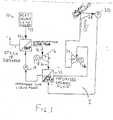
- reference numeral 10 designates an embodiment of apparatus for producing power in accordance with the present invention.
- the apparatus comprises intermediate fluid heater/vaporizer 12 through which vaporized intermediate fluid is produced using heat from heat source 13, e.g. using heat contained in hot gases, etc.
- the vaporized intermediate fluid is supplied to organic working fluid vaporizer 22 where it is condensed by transferring heat to organic fluid present in the vaporizer so that vaporized organic fluid is produced.
- Intermediate fluid condensate produced is returned to intermediate fluid heater/vaporizer 12 using pump 19.
- the vaporized organic fluid is supplied to organic vapor turbine 24 wherein it expands and produces power.
- generator 26 is driven by organic vapor turbine 24 and produces electricity.
- Expanded vaporized organic fluid exiting organic vapor turbine 24 is supplied to organic fluid condenser 28 and organic fluid condensate is produced.
- Pump 30 supplies organic fluid condensate exiting organic fluid condenser 28 to organic working fluid vaporizer 22.
- the vaporized intermediate fluid prior to supplying vaporized intermediate fluid vaporizer 22, the vaporized intermediate fluid is supplied to intermediate fluid turbine 16 wherein the vaporized intermediate fluid expands and produces power. Also here, preferably, intermediate fluid turbine 16 drives generator 18 that produces electricity.
- intermediate fluid present in intermediate fluid vaporizer 12 extracts heat from heat source 13, e.g. hot gases and intermediate fluid vapor is produced.
- the intermediate fluid vapor is supplied preferably to intermediate fluid turbine 16 and expands therein producing power and expanded intermediate fluid vapor exits intermediate fluid turbine 16. Since preferably, generator 18 is coupled to intermediate fluid turbine 16 electricity is produced.
- Expanded intermediate fluid vapor exiting intermediate fluid turbine 16 is supplied via line or conduit 20 to organic working fluid vaporizer 22.
- Organic working fluid present in organic working fluid vaporizer 22 cools the expanded intermediate fluid vapor and intermediate fluid condensate as well as vaporized organic working fluid is produced.
- Intermediate fluid condensate is supplied using pump 19 to intermediate fluid vaporizer 12.
- Vaporized organic working fluid is supplied to organic working fluid turbine 24 wherein it expands and power is produced. Expanded organic working fluid vapor exits organic working fluid turbine 24. Preferably, organic working fluid turbine 24 is coupled to a generator 26 and electricity is produced. The expanded organic working fluid vapor is supplied to organic working fluid condenser 28 that is preferably air-cooled and organic working fluid condensate is produced. Pump 30 supplies organic working fluid condensate to organic working fluid vaporizer 22.
- the intermediate fluid comprises an organic, alkylated heat transfer fluid.
- the intermediate fluid is a synthetic alkylated aromatic heat transfer fluid.
- the preferred intermediate fluid is advantageous since their use avoids problems of freezing, operates without being at vacuum conditions and there is no need for treatment. Water usually needs treatment when used as an intermediate fluid.
- the synthetic, alkylated, aromatic heat transfer fluid is useful in a relative high temperature range: vaporizing temperature between about 250°C and about 315°C. At these temperatures, the pressure of the intermediate fluid is between about 495kPA and 1560kPA. The relatively low pressures mentioned above make this type of fluid particularly suitable for use in the present invention.
- the condensing temperature of the intermediate fluid on the intermediate fluid side of organic working fluid vaporizer 22 will preferably be in the range of about 190°C to about 140°C but can be much lower if need be.
- the use of this type of intermediate fluid as a heat transfer medium for transferring heat from the heat source to the organic working fluid and as well as producing power form the intermediate fluid increases the efficiency of the power producing system on a whole.
- the organic working fluid comprises pentane, either n-pentane or iso-pentane.
- preferred organic fluid power cycle I can include a pre-heater, superheater and recuperator.
- generators 18 and 26 can be replaced by a single common generator driven by turbines 16 and 24 either using dual shaft ends in the single common generator or through a gear drive. Most preferred, the common generator is interposed between turbines 16 and 24.
- intermediate fluid condensate produced in organic working fluid vaporizer 22 can be used to pre-heat the organic working fluid prior to it entering the organic working fluid vaporizer.
- the intermediate fluid cycle can include a recuperator.
- An example of such a cycle is shown in Fig. 2 wherein numeral 10A designates another embodiment of the present invention and is presently considered the best mode for carrying out the present invention.
- numeral 21 designates an intermediate fluid recuperator in which heat is transferred from expanded intermediate fluid vapor exiting intermediate fluid turbine 16 to intermediate fluid condensate supplied by pump 19A from the intermediate fluid side of organic working fluid vaporizer 22.
- portion of the heated intermediate fluid condensate exiting intermediate fluid recuperator 21 is supplied to organic fluid pre-heater 23 for pre-heating the organic working fluid prior to supplying it to organic working fluid vaporizer 22.
- a further portion of the heated intermediate fluid condensate exiting intermediate fluid recuperator 21 is supplied to intermediate fluid vaporizer 12.
- organic working fluid recuperator 27 is included and is used for transferring heat from expanded organic working fluid vapor exiting organic working fluid turbine 24 to organic working fluid condensate supplied by pump 30A from organic working fluid condenser 28.
- Heated organic working fluid condensate exiting organic working fluid recuperator 27 is supplied to organic working fluid pre-heater 23.
- numeral 10B designates a further embodiment of the present invention.
- this embodiment preferred, rather than supplying all of the intermediate fluid expanded vapor exiting intermediate fluid turbine 16 to organic working fluid vaporizer 22, only portion of the intermediate fluid expanded vapor can be supplied to organic working fluid vaporizer 22.
- the other portion of the intermediate fluid expanded vapor can be supplied to suitable heat load 32.
- Heat load 32 extracts the required heat from the other portion of intermediate fluid expanded vapor and preferably produces intermediate fluid condensate that is returned to intermediate fluid vaporizer 12 using pump 34.
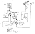
- FIG. 4 designates an additional embodiment of the present invention.
- another heat load 42 can be supplied with heat from intermediate fluid condensate or portion thereof that exits organic working fluid vaporizer 22.
- the heat depleted intermediate fluid condensate exiting other heat load 42 is supplied, using pump 44, to intermediate fluid heater/vaporizer 12.
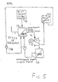
- numeral 10D designates a still further embodiment of the present invention.
- the organic fluid power cycle is eliminated and merely intermediate power cycle 50 is used for producing power as well as supplying heat load 52.
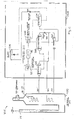
- numeral 10E refers to a still further embodiment of the present invention wherein a further example of a cycle including a recuperator in the intermediate fluid cycle is shown.
- numeral 21E designates an intermediate fluid recuperator in which heat is transferred from expanded intermediate fluid vapor exiting intermediate fluid turbine 16E to intermediate fluid condensate supplied by pump 19E from the intermediate fluid or shell side of organic working fluid vaporizer 22E.
- portion of the intermediate fluid condensate exiting the intermediate fluid side of organic working fluid vaporizer 22E is supplied to organic fluid pre-heater 23E for pre-heating the organic working fluid prior to supplying it to organic working fluid vaporizer 22E.
- a further portion of the intermediate fluid condensate exiting the intermediate fluid side of organic working fluid vaporizer 22E is supplied to intermediate fluid recuperator 21E.
- heat from heat sourse 13E is added to the intermediate fluid condensate exiting organic pre-heater 23E. Consequently, the heat transferred from the intermediate fluid condensate to the organic working fluid in pre-heater 23E enables further heat to be extracted from heat source 13E.
- organic working fluid recuperator 27E is included and is used for transferring heat from expanded organic working fluid vapor exiting organic working fluid turbine 24E to organic working fluid condensate supplied by pump 30E from organic working fluid condenser 28E.
- Heated organic working fluid condensate exiting organic working fluid recuperator 27E is supplied to organic working fluid pre-heater 23E.
- this embodiment is similar to the embodiment described with relation to Fig. 1 and also operates in a similar manner.
- all of the intermediate fluid exiting the intermediate fluid side of the organic working fluid vaporizer 22E can be supplied to organic working fluid pre-heater 23E. Thereafter, the cooled intermediate fluid exiting to organic working fluid pre-heater 23E can be supplied to heat source 13E, the heated intermediate fluid exiting heat source 13E being supplied to intermediate fluid recuperator 21E.
- the organic working fluid for this embodiment and all other embodiments mentioned herein comprises pentane, that is, iso-pentane and n-pentane.
- generator 18E is preferably shared by the output of intermediate turbine 16E and organic working fluid turbine 24E. This is because intermediate turbine 16E can operate efficiently at relatively low rotational speeds (1500-1800 RPM), permitting it to be directly coupled to generator 18E whose rotation speed is also relatively low (1500-1800 RPM). Similarly the rotational speed of organic working fluid turbine 24E can also be relatively low (1500-1800 RPM), permitting it also to be directly coupled to generator 18E. Thus generator 18E is interposed between intermediate fluid turbine 16E and organic working fluid turbine 24E. However, if preferred, separate generators can be provided.
- the embodiment described with reference to Fig. 6 comprises two separate entities, heat source unit or heat recovery vapor generator 40E and power cycle unit 50E.
- Heat recovery vapor generator 40E is a once-through heater/vaporizer comprising the heater bundles and structure, exhaust gas duct-work, diverter valve and actuators, exhaust stack and by-pass stack.
- the purpose of the heat acquisition subsystem is to: a) direct and control/meter the gas turbines' waste heat to the heat recovery vapor generator using a diverter valve; b) convert the heat contained in the combustion gases to vapor; and c) discard the cooled combustion gases to the atmosphere through a further exhaust stack 11E.
- Heat recovery vapor generator 40E is a tube/pipe heat exchanger in which the intermediate fluid or thermal oil, flowing in the tubes, is heated and vaporized by the combustion gases flowing on the shell side. After being cooled, the combustion gases are discarded to the atmosphere through exhaust stack 11E. Heating and vaporizing occur in a once-through heater design.
- This intermediate fluid or thermal oil vapor leaves the heat recovery vapor generator 40E slightly wet. The wet vapor is directed to a separator wherein its moisture is removed by a gravity separator. Dry vapor, leaving the top of the separator, is directed to intermediate fluid or topping turbine 16E. The liquid intermediate fluid or thermal oil, leaving the bottom of the separator, is returned to the heat recovery vapor generator.
- intermediate fluid turbine 16E The dry, separated intermediate fluid or thermal oil vapor directed to intermediate fluid turbine 16E is expanded to lower pressure.
- Intermediate fluid or topping turbine 16E, as well as organic working fluid or bottoming turbine 24E are both multi-staged (2 or 3 stages) axial, impulse-type turbines, preferably directly connected to opposite ends of generator 18E, as shown. Since the intermediate fluid or thermal oil is a hydrocarbon-based fluid (like pentane), the geometry and flow path of the intermediate fluid turbine 16E resembles that of organic working fluid turbine 24E.
- the intermediate fluid of the embodiment shown in Fig. 6 comprises an organic, alkylated heat transfer fluid.
- intermediate fluid is a synthetic alkylated aromatic heat transfer fluid.
- the most preferred examples of the intermediate fluid at present are the thermal oils Therminol LT fluid and Dowtherm J.
- Therminol LT is the commercial name for the alkyl substituted aromatic fluid of the Solutia Company having a center in Belgium.
- Dowtherm J is the commercial name for a mixture of isomers of an alkylated aromatic fluid of the Dow Chemical Company being centered in the U.S.A.
- Fluids such as Therminol LT and Dowtherm J are stable to temperatures near 340°C and as such are capable of better utilizing the high temperature portion of the gas turbine's waste heat more efficiently than pentane.
- Other most preferred examples of the intermediate fluids are isomers of diethyl benzene and mixtures of the isomers as well as butyl benzene.
- Examples of heat sources from which the present invention can extract heat from are waste heat from gas turbines, waste heat from other industrial processes, waste heat produced in cement manufacture and in the cement manufacturing industry, heat produced by the combustion of biomass fuel, etc.
- the embodiments of the present invention describe the use of generators 18 or 26 or the use of a common generator for producing electricity
- the power produced by turbines 16 and 24 or either of them can be used as a mechanical power.
- they can run a compressor, other loads, etc.
- the preferred organic working fluid is pentane, that is, iso-pentane and n-pentane
- other fluids such as butane and iso-butane, hexane and iso-hexane as well as additional fluids such as hydrocarbons, for example aliphatic parrafins in their normal and isomeric form
- hydrocarbons for example aliphatic parrafins in their normal and isomeric form
- mixtures of the above mentioned fluids can also be used as the working fluid for the above described invention and its embodiments.
Landscapes
- Engineering & Computer Science (AREA)
- Chemical & Material Sciences (AREA)
- Combustion & Propulsion (AREA)
- Mechanical Engineering (AREA)
- General Engineering & Computer Science (AREA)
- Engine Equipment That Uses Special Cycles (AREA)
Claims (4)
- Procédé de production d'énergie électrique à partir d'une source de chaleur en utilisant un fluide intermédiaire pour transférer la chaleur d'une source de chaleur vers un fluide de travail organique, comprenant les étapes consistant à :a) chauffer un fluide intermédiaire avec de la chaleur provenant de la source de chaleur (13), et produire un fluide intermédiaire vaporisé dans un réchauffeur/ évaporateur de fluide intermédiaire (12) ;b) vaporiser un fluide de travail liquide organique avec la chaleur provenant du fluide intermédiaire vaporisé dans un évaporateur de fluide organique (22) pour former un condensat de fluide de travail organique et de fluide intermédiaire vaporisé ;c) détendre le fluide intermédiaire vaporisé dans une turbine à vapeur de fluide intermédiaire (16) pour produire l'énergie électrique avant de fournir ce fluide intermédiaire vaporisé à l'évaporateur de fluide organique (22) ;d) détendre le fluide de travail organique vaporisé dans une turbine à vapeur organique (24) pour générer l'énergie électrique et produire un fluide de travail organique vaporisé détendu ;e) condenser le fluide de travail vaporisé organique détendu pour produire un condensat de fluide organique ; etf) fournir le condensat de fluide organique à l'évaporateur de fluide organique (22),caractérisé en ce que
le fluide intermédiaire est un fluide de transfert de chaleur synthétique, alkylé, aromatique. - Procédé selon la revendication 1,
caractérisé en ce que
le condensat de fluide intermédiaire est fourni au réchauffeur/évaporateur de fluide intermédiaire (12). - Dispositif de production d'énergie électrique à partir d'une source de chaleur (13) ayant un cycle de fluide intermédiaire comprenant un évaporateur de fluide intermédiaire (12), une turbine de fluide intermédiaire (16) et un condenseur de fluide intermédiaire (22),
caractérisé para) un réchauffeur/évaporateur de fluide intermédiaire (12) qui chauffe et vaporise le fluide intermédiaire avec de la chaleur provenant de la source de chaleur (13) et produit un fluide intermédiaire vaporisé ;b) un évaporateur de fluide organique (22) qui vaporise un fluide de travail liquide organique avec la chaleur provenant du fluide intermédiaire vaporisé pour former un condensat de fluide de travail organique et de fluide intermédiaire vaporisé ;c) une turbine à vapeur de fluide intermédiaire (16) qui détend le fluide intermédiaire vaporisé avant de le fournir à l'évaporateur de fluide organique (22), de telle sorte que la turbine à vapeur de fluide intermédiaire (16) produise l'énergie électrique ;d) une turbine à vapeur organique (24) qui détend le fluide de travail organique vaporisé et génère l'énergie électrique et produit le fluide de travail organique vaporisé détendu ;e) un condenseur de fluide organique (28) qui condense le fluide de travail vaporisé organique détendu pour produire un condensat de fluide de travail organique fourni à l'évaporateur de fluide de travail organique,caractérisé en ce que
le fluide intermédiaire est un fluide de transfert de chaleur synthétique, alkylé, aromatique. - Dispositif selon la revendication 3,
comprenant une pompe (19) pour fournir le condensat de fluide intermédiaire au réchauffeur/évaporateur de fluide intermédiaire (12).
Applications Claiming Priority (4)
| Application Number | Priority Date | Filing Date | Title |
|---|---|---|---|
| US617911 | 1984-06-06 | ||
| US61791100A | 2000-07-17 | 2000-07-17 | |
| US70271100A | 2000-11-01 | 2000-11-01 | |
| US702711 | 2000-11-01 |
Publications (3)
| Publication Number | Publication Date |
|---|---|
| EP1174590A2 EP1174590A2 (fr) | 2002-01-23 |
| EP1174590A3 EP1174590A3 (fr) | 2003-09-10 |
| EP1174590B1 true EP1174590B1 (fr) | 2007-03-07 |
Family
ID=27088120
Family Applications (1)
| Application Number | Title | Priority Date | Filing Date |
|---|---|---|---|
| EP01117269A Expired - Lifetime EP1174590B1 (fr) | 2000-07-17 | 2001-07-17 | Méthode et appareil pour produire de la puissance à partir de chaleur |
Country Status (10)
| Country | Link |
|---|---|
| US (2) | US6960839B2 (fr) |
| EP (1) | EP1174590B1 (fr) |
| CN (1) | CN1316146C (fr) |
| AR (1) | AR029849A1 (fr) |
| AT (1) | ATE356279T1 (fr) |
| BR (1) | BR0102935A (fr) |
| CA (1) | CA2353152C (fr) |
| DE (1) | DE60127040T2 (fr) |
| ES (1) | ES2281389T3 (fr) |
| MX (1) | MXPA01007239A (fr) |
Families Citing this family (103)
| Publication number | Priority date | Publication date | Assignee | Title |
|---|---|---|---|---|
| US6960839B2 (en) * | 2000-07-17 | 2005-11-01 | Ormat Technologies, Inc. | Method of and apparatus for producing power from a heat source |
| DE10238435A1 (de) * | 2002-08-16 | 2004-02-19 | Linde Ag | Verfahren und Vorrichtung zum Erzeugen eines verdichteten Gasstroms |
| GB2405458B (en) * | 2003-08-27 | 2006-12-20 | Freepower Ltd | Power control |
| BRPI0413986A (pt) * | 2003-08-27 | 2006-11-07 | Ttl Dynamics Ltd | sistema de recuperação de energia, usos de hfe-7100 ou hexano ou água e de um dos alcanos, sistema de geração de energia elétrica, unidade de turbina de afluxo radial, mancal, acoplamento magnético rotativo, método realizado em um sistema de recuperação de energia para extrair energia a apartir de uma fonte de calor residual, método de controle de um sistema de recuperação de energia, e, sistemas de controle programável e de purificação de fluido de trabalho para um sistema de conversão de energia |
| SE525918C2 (sv) | 2003-09-10 | 2005-05-24 | Eta Entrans Ab | System för värmeförädling |
| IL157887A (en) * | 2003-09-11 | 2006-08-01 | Ormat Ind Ltd | Method and apparatus for augmenting the pressure head of gas flowing in a pipeline |
| US7047744B1 (en) * | 2004-09-16 | 2006-05-23 | Robertson Stuart J | Dynamic heat sink engine |
| US7225621B2 (en) * | 2005-03-01 | 2007-06-05 | Ormat Technologies, Inc. | Organic working fluids |
| EP1869293B1 (fr) * | 2005-03-29 | 2013-05-08 | UTC Power Corporation | Cycles de rankine organiques en cascade utilises pour recuperer la chaleur |
| US7493763B2 (en) | 2005-04-21 | 2009-02-24 | Ormat Technologies, Inc. | LNG-based power and regasification system |
| US8181463B2 (en) * | 2005-10-31 | 2012-05-22 | Ormat Technologies Inc. | Direct heating organic Rankine cycle |
| US20070214804A1 (en) * | 2006-03-15 | 2007-09-20 | Robert John Hannan | Onboard Regasification of LNG |
| US20070214805A1 (en) * | 2006-03-15 | 2007-09-20 | Macmillan Adrian Armstrong | Onboard Regasification of LNG Using Ambient Air |
| US8069677B2 (en) * | 2006-03-15 | 2011-12-06 | Woodside Energy Ltd. | Regasification of LNG using ambient air and supplemental heat |
| US20080053093A1 (en) * | 2006-08-29 | 2008-03-06 | Chang Sun Kim | Uniform pressure unequal surface engine and engine for power generators using the same |
| AU2007295938A1 (en) * | 2006-09-11 | 2008-03-20 | Woodside Energy Limited | Power generation system for a marine vessel |
| US8438849B2 (en) | 2007-04-17 | 2013-05-14 | Ormat Technologies, Inc. | Multi-level organic rankine cycle power system |
| US8561405B2 (en) * | 2007-06-29 | 2013-10-22 | General Electric Company | System and method for recovering waste heat |
| WO2009045196A1 (fr) * | 2007-10-04 | 2009-04-09 | Utc Power Corporation | Système de cycle de rankine organique (orc) en cascade utilisant de la chaleur résiduelle d'un moteur alternatif |
| DE102008019906A1 (de) * | 2007-10-14 | 2009-04-16 | Ingelheim, Peter, Graf Von | Wärmekraftwerk für Dämpfe und seine Prozesse |
| US7866157B2 (en) | 2008-05-12 | 2011-01-11 | Cummins Inc. | Waste heat recovery system with constant power output |
| US20090284011A1 (en) * | 2008-05-16 | 2009-11-19 | Mcbride Thomas S | Continuos-Absorption Turbine |
| US8266908B2 (en) * | 2008-06-30 | 2012-09-18 | Ormat Technologies, Inc. | Multi-heat source power plant |
| US8297355B2 (en) * | 2008-08-22 | 2012-10-30 | Texaco Inc. | Using heat from produced fluids of oil and gas operations to produce energy |
| DE102008046509B4 (de) * | 2008-09-10 | 2022-02-24 | Man Energy Solutions Se | Vorrichtung zur Energierückgewinnung für einen Großdieselmotor |
| US8087248B2 (en) * | 2008-10-06 | 2012-01-03 | Kalex, Llc | Method and apparatus for the utilization of waste heat from gaseous heat sources carrying substantial quantities of dust |
| JP5123148B2 (ja) * | 2008-12-04 | 2013-01-16 | 川崎重工業株式会社 | 排熱回収タービン装置 |
| US8616323B1 (en) | 2009-03-11 | 2013-12-31 | Echogen Power Systems | Hybrid power systems |
| DE102009013570A1 (de) * | 2009-03-17 | 2010-09-30 | Siemens Aktiengesellschaft | Kraftwerksanlage mit zwei Kreisläufen sowie ein Verfahren zum Betrieb einer Kraftwerksanlage |
| US20100242476A1 (en) * | 2009-03-30 | 2010-09-30 | General Electric Company | Combined heat and power cycle system |
| EP2419621A4 (fr) | 2009-04-17 | 2015-03-04 | Echogen Power Systems | Système et procédé pour gérer des problèmes thermiques dans des moteurs à turbine à gaz |
| US8850814B2 (en) * | 2009-06-11 | 2014-10-07 | Ormat Technologies, Inc. | Waste heat recovery system |
| JP5681711B2 (ja) | 2009-06-22 | 2015-03-11 | エコージェン パワー システムズ インコーポレイテッドEchogen Power Systems Inc. | 1または2以上の工業プロセスでの熱流出物処理方法および装置 |
| US20100319346A1 (en) * | 2009-06-23 | 2010-12-23 | General Electric Company | System for recovering waste heat |
| US8237299B2 (en) * | 2009-06-26 | 2012-08-07 | Larry Andrews | Power generation systems, processes for generating energy at an industrial mine site, water heating systems, and processes of heating water |
| US8544274B2 (en) * | 2009-07-23 | 2013-10-01 | Cummins Intellectual Properties, Inc. | Energy recovery system using an organic rankine cycle |
| US9316404B2 (en) | 2009-08-04 | 2016-04-19 | Echogen Power Systems, Llc | Heat pump with integral solar collector |
| US20110030391A1 (en) * | 2009-08-06 | 2011-02-10 | Woodside Energy Limited | Mechanical Defrosting During Continuous Regasification of a Cryogenic Fluid Using Ambient Air |
| US8627663B2 (en) * | 2009-09-02 | 2014-01-14 | Cummins Intellectual Properties, Inc. | Energy recovery system and method using an organic rankine cycle with condenser pressure regulation |
| DE102009040300A1 (de) * | 2009-09-04 | 2011-05-12 | Conpower Energieanlagen Gmbh & Co Kg. | Verfahren und Einrichtung zur Energieerzeugung insbesondere aus Biomasse oder Biomasseenergieträgern |
| US8813497B2 (en) | 2009-09-17 | 2014-08-26 | Echogen Power Systems, Llc | Automated mass management control |
| US8613195B2 (en) | 2009-09-17 | 2013-12-24 | Echogen Power Systems, Llc | Heat engine and heat to electricity systems and methods with working fluid mass management control |
| US8869531B2 (en) | 2009-09-17 | 2014-10-28 | Echogen Power Systems, Llc | Heat engines with cascade cycles |
| US8794002B2 (en) | 2009-09-17 | 2014-08-05 | Echogen Power Systems | Thermal energy conversion method |
| US8459029B2 (en) | 2009-09-28 | 2013-06-11 | General Electric Company | Dual reheat rankine cycle system and method thereof |
| US8276379B2 (en) * | 2009-11-16 | 2012-10-02 | General Electric Company | Systems and apparatus relating to solar-thermal power generation |
| US8490397B2 (en) * | 2009-11-16 | 2013-07-23 | General Electric Company | Compound closed-loop heat cycle system for recovering waste heat and method thereof |
| US20120017591A1 (en) * | 2010-01-19 | 2012-01-26 | Leveson Philip D | Simultaneous production of electrical power and potable water |
| IN2012DN05179A (fr) | 2010-01-26 | 2015-10-23 | Tmeic Corp | |
| ITUD20100044A1 (it) * | 2010-03-09 | 2011-09-10 | Vittorio Centa | Impianto di produzione di energia a ciclo chiuso |
| IT1400467B1 (it) * | 2010-03-25 | 2013-06-11 | Nasini | Impianto per la produzione di energia basato sul ciclo rankine a fluido organico. |
| EP2378089A1 (fr) * | 2010-04-13 | 2011-10-19 | ABB Schweiz AG | Système de conversion pour convertir une chaleur de déchets en puissance d'arbre |
| US8752381B2 (en) * | 2010-04-22 | 2014-06-17 | Ormat Technologies Inc. | Organic motive fluid based waste heat recovery system |
| RU2433282C2 (ru) * | 2010-05-07 | 2011-11-10 | Владимир Петрович Севастьянов | Способ псевдодетонационной газификации угольной суспензии в комбинированном цикле "icsgcc" |
| CN103237961B (zh) | 2010-08-05 | 2015-11-25 | 康明斯知识产权公司 | 采用有机朗肯循环的排放临界增压冷却 |
| DE112011102672B4 (de) | 2010-08-09 | 2022-12-29 | Cummins Intellectual Properties, Inc. | Abwärmerückgewinnungssystem und Verbrennungsmotorsystem zum Einfangen von Energie nach Motornachbehandlungssytemen |
| DE112011102675B4 (de) | 2010-08-11 | 2021-07-15 | Cummins Intellectual Property, Inc. | Geteilter Radiatoraufbau zur Wärmeabfuhroptimierung für ein Abwärmeverwertungssystem |
| CN103180554B (zh) | 2010-08-13 | 2016-01-20 | 康明斯知识产权公司 | 使用换能装置旁通阀进行兰金循环冷凝器压力控制 |
| US8549838B2 (en) | 2010-10-19 | 2013-10-08 | Cummins Inc. | System, method, and apparatus for enhancing aftertreatment regeneration in a hybrid power system |
| US8616001B2 (en) | 2010-11-29 | 2013-12-31 | Echogen Power Systems, Llc | Driven starter pump and start sequence |
| US8857186B2 (en) | 2010-11-29 | 2014-10-14 | Echogen Power Systems, L.L.C. | Heat engine cycles for high ambient conditions |
| US8783034B2 (en) | 2011-11-07 | 2014-07-22 | Echogen Power Systems, Llc | Hot day cycle |
| US8742701B2 (en) | 2010-12-20 | 2014-06-03 | Cummins Inc. | System, method, and apparatus for integrated hybrid power system thermal management |
| US8826662B2 (en) | 2010-12-23 | 2014-09-09 | Cummins Intellectual Property, Inc. | Rankine cycle system and method |
| DE112011104516B4 (de) | 2010-12-23 | 2017-01-19 | Cummins Intellectual Property, Inc. | System und Verfahren zur Regulierung einer EGR-Kühlung unter Verwendung eines Rankine-Kreisprozesses |
| DE102012000100A1 (de) | 2011-01-06 | 2012-07-12 | Cummins Intellectual Property, Inc. | Rankine-kreisprozess-abwärmenutzungssystem |
| US9021808B2 (en) | 2011-01-10 | 2015-05-05 | Cummins Intellectual Property, Inc. | Rankine cycle waste heat recovery system |
| EP3214296B1 (fr) | 2011-01-20 | 2018-09-12 | Cummins Intellectual Properties, Inc. | Système récupérateur de chaleur résiduelle à cycle de rankine et procédé de régulation de température de rge améliorée |
| US8707914B2 (en) | 2011-02-28 | 2014-04-29 | Cummins Intellectual Property, Inc. | Engine having integrated waste heat recovery |
| US8650879B2 (en) * | 2011-04-20 | 2014-02-18 | General Electric Company | Integration of waste heat from charge air cooling into a cascaded organic rankine cycle system |
| JP5999322B2 (ja) * | 2011-06-03 | 2016-09-28 | 戸田工業株式会社 | 発電システム |
| US20120324885A1 (en) * | 2011-06-27 | 2012-12-27 | Turbine Air Systems Ltd. | Geothermal power plant utilizing hot geothermal fluid in a cascade heat recovery apparatus |
| US8667799B2 (en) * | 2011-07-25 | 2014-03-11 | Ormat Technologies Inc. | Cascaded power plant using low and medium temperature source fluid |
| US9671138B2 (en) | 2011-07-25 | 2017-06-06 | Ormat Technologies, Inc. | Cascaded power plant using low and medium temperature source fluid |
| EP2559867A1 (fr) | 2011-08-19 | 2013-02-20 | Alstom Technology Ltd | Procédé de production d'énergie électrique à l'aide d'une centrale électrique combinée et centrale électrique combinée destinée à l'exécution du procédé |
| WO2013055391A1 (fr) | 2011-10-03 | 2013-04-18 | Echogen Power Systems, Llc | Cycle de réfrigération du dioxyde de carbone |
| US8534039B1 (en) * | 2012-04-16 | 2013-09-17 | TAS Energy, Inc. | High performance air-cooled combined cycle power plant with dual working fluid bottoming cycle and integrated capacity control |
| US8893495B2 (en) | 2012-07-16 | 2014-11-25 | Cummins Intellectual Property, Inc. | Reversible waste heat recovery system and method |
| KR20150143402A (ko) | 2012-08-20 | 2015-12-23 | 에코진 파워 시스템스, 엘엘씨 | 직렬 구성의 터보 펌프와 시동 펌프를 갖는 초임계 작동 유체 회로 |
| AU2012216352B2 (en) | 2012-08-22 | 2015-02-12 | Woodside Energy Technologies Pty Ltd | Modular LNG production facility |
| US9188347B1 (en) | 2012-09-01 | 2015-11-17 | Home Energy Technologies, Inc. | Remote distance transporting and integrating heat ejection connected to central heating ductwork (auxiliary heat ejectors) |
| US9341084B2 (en) | 2012-10-12 | 2016-05-17 | Echogen Power Systems, Llc | Supercritical carbon dioxide power cycle for waste heat recovery |
| US9118226B2 (en) | 2012-10-12 | 2015-08-25 | Echogen Power Systems, Llc | Heat engine system with a supercritical working fluid and processes thereof |
| DE102012110579B4 (de) * | 2012-11-05 | 2019-03-14 | Esi Gmbh | Anlage und Verfahren zur Erzeugung von Prozessdampf |
| US9140209B2 (en) | 2012-11-16 | 2015-09-22 | Cummins Inc. | Rankine cycle waste heat recovery system |
| US9410451B2 (en) | 2012-12-04 | 2016-08-09 | General Electric Company | Gas turbine engine with integrated bottoming cycle system |
| US9638065B2 (en) | 2013-01-28 | 2017-05-02 | Echogen Power Systems, Llc | Methods for reducing wear on components of a heat engine system at startup |
| WO2014117074A1 (fr) | 2013-01-28 | 2014-07-31 | Echogen Power Systems, L.L.C. | Procédé de commande d'un robinet de débit d'une turbine de travail au cours d'un cycle de rankine supercritique au dioxyde de carbone |
| DE102013202111B4 (de) * | 2013-02-08 | 2015-06-03 | Siemens Aktiengesellschaft | Abwärmenutzung und Leistungserhöhung von Gasturbinenanlagen |
| JP2016519731A (ja) | 2013-03-04 | 2016-07-07 | エコージェン パワー システムズ エル.エル.シー.Echogen Power Systems, L.L.C. | 高正味電力の超臨界二酸化炭素回路を有する熱機関システム |
| US20160040560A1 (en) * | 2013-04-02 | 2016-02-11 | Aliasghar Hariri | Power Generation by Converting Low Grade Thermal Energy to Hydropower |
| US9845711B2 (en) | 2013-05-24 | 2017-12-19 | Cummins Inc. | Waste heat recovery system |
| DE102013212805A1 (de) | 2013-07-01 | 2015-01-08 | Evonik Industries Ag | Verwendung von hoch effizienten Arbeitsmedien für Wärmekraftmaschinen |
| US9869495B2 (en) | 2013-08-02 | 2018-01-16 | Martin Gordon Gill | Multi-cycle power generator |
| GB2526090B (en) * | 2014-05-12 | 2020-10-07 | Cummins Ltd | Turbine generator |
| US10570777B2 (en) | 2014-11-03 | 2020-02-25 | Echogen Power Systems, Llc | Active thrust management of a turbopump within a supercritical working fluid circuit in a heat engine system |
| US10883388B2 (en) | 2018-06-27 | 2021-01-05 | Echogen Power Systems Llc | Systems and methods for generating electricity via a pumped thermal energy storage system |
| US11435120B2 (en) | 2020-05-05 | 2022-09-06 | Echogen Power Systems (Delaware), Inc. | Split expansion heat pump cycle |
| CA3201373A1 (fr) | 2020-12-09 | 2022-06-16 | Timothy Held | Systeme de stockage d'energie thermique electrique a trois reservoirs |
| WO2023277720A1 (fr) * | 2021-07-01 | 2023-01-05 | Владимир Петрович СЕВАСТЬЯНОВ | Ekranoplane porte-aéronef nucléaire (epan) et fonction de propulsion de celui-ci |
| US12516855B2 (en) | 2022-10-27 | 2026-01-06 | Supercritical Storage Company, Inc. | High-temperature, dual rail heat pump cycle for high performance at high-temperature lift and range |
| CN120858221A (zh) | 2023-02-07 | 2025-10-28 | 超临界存储公司 | 废热与泵送热能存储的集成 |
| US12523172B1 (en) * | 2024-07-12 | 2026-01-13 | Rtx Corporation | Cryogenic bottoming cycle adaptable heat rejection loop split |
Family Cites Families (33)
| Publication number | Priority date | Publication date | Assignee | Title |
|---|---|---|---|---|
| US3648456A (en) * | 1970-08-17 | 1972-03-14 | Du Pont | Power generation with rankine cycle engines using alkylated adamantanes as a working fluid |
| US4279125A (en) * | 1975-06-23 | 1981-07-21 | Occidental Research Corporation | Process and system for recovery of energy from geothermal brines and other hot water containing sources |
| US4104535A (en) | 1976-04-23 | 1978-08-01 | Ormat Turbines (1965) Ltd. | Hybrid electric power generating system |
| US4132075A (en) | 1977-06-30 | 1979-01-02 | Union Oil Company Of California | Method of producing mechanical energy from geothermal brine |
| US4428190A (en) * | 1981-08-07 | 1984-01-31 | Ormat Turbines, Ltd. | Power plant utilizing multi-stage turbines |
| US4760705A (en) * | 1983-05-31 | 1988-08-02 | Ormat Turbines Ltd. | Rankine cycle power plant with improved organic working fluid |
| US4542625A (en) * | 1984-07-20 | 1985-09-24 | Bronicki Lucien Y | Geothermal power plant and method for operating the same |
| US4693087A (en) * | 1984-10-25 | 1987-09-15 | Thermal Engine Technology, Inc. | Method of generating power from a vapor |
| US4864826A (en) * | 1984-10-25 | 1989-09-12 | Lagow Ralph J | Method and apparatus for generating power from a vapor |
| US5483797A (en) * | 1988-12-02 | 1996-01-16 | Ormat Industries Ltd. | Method of and apparatus for controlling the operation of a valve that regulates the flow of geothermal fluid |
| US5038567A (en) * | 1989-06-12 | 1991-08-13 | Ormat Turbines, Ltd. | Method of and means for using a two-phase fluid for generating power in a rankine cycle power plant |
| US5437157A (en) * | 1989-07-01 | 1995-08-01 | Ormat Industries Ltd. | Method of and apparatus for cooling hot fluids |
| IL101002A (en) | 1991-02-20 | 2001-01-28 | Ormat Turbines 1965 Ltd | Method of and means for using a two phase fluid for generating power in a rankine cycle power plant |
| JPH07501164A (ja) * | 1991-11-21 | 1995-02-02 | イマジネイション テクノロジーズ リミテッド | ビデオ/グラフィックメモリシステム |
| US5349834A (en) | 1992-03-17 | 1994-09-27 | Tortoise Products, Inc. | Adhesively mounted security system |
| US5400598A (en) * | 1993-05-10 | 1995-03-28 | Ormat Industries Ltd. | Method and apparatus for producing power from two-phase geothermal fluid |
| NZ264077A (en) * | 1993-08-02 | 1996-05-28 | Ormat Ind Ltd | Geothermal power plant sealing system for containing leakage from high pressure end seal of back pressure turbine |
| US5860279A (en) * | 1994-02-14 | 1999-01-19 | Bronicki; Lucien Y. | Method and apparatus for cooling hot fluids |
| US5687570A (en) * | 1994-02-28 | 1997-11-18 | Ormat Industries Ltd. | Externally fired combined cycle gas turbine system |
| US5704209A (en) * | 1994-02-28 | 1998-01-06 | Ormat Industries Ltd | Externally fired combined cycle gas turbine system |
| US5799490A (en) * | 1994-03-03 | 1998-09-01 | Ormat Industries Ltd. | Externally fired combined cycle gas turbine |
| JP3920365B2 (ja) * | 1994-04-28 | 2007-05-30 | オルマット インダストリーズ リミテッド | 地熱流体中の非凝縮性ガスを処理するための装置および方法 |
| TR199501702A2 (tr) * | 1994-12-29 | 1997-03-21 | Ormat Ind Ltd | Jeotermal akiskandan güc üretmek icin usul ve cihaz. |
| US5640842A (en) * | 1995-06-07 | 1997-06-24 | Bronicki; Lucien Y. | Seasonally configurable combined cycle cogeneration plant with an organic bottoming cycle |
| US5687050A (en) * | 1995-07-25 | 1997-11-11 | Ficht Gmbh | Electronic control circuit for an internal combustion engine |
| US5664414A (en) * | 1995-08-31 | 1997-09-09 | Ormat Industries Ltd. | Method of and apparatus for generating power |
| JPH09209716A (ja) | 1996-02-07 | 1997-08-12 | Toshiba Corp | 発電プラント |
| US5953918A (en) | 1998-02-05 | 1999-09-21 | Exergy, Inc. | Method and apparatus of converting heat to useful energy |
| US6052997A (en) * | 1998-09-03 | 2000-04-25 | Rosenblatt; Joel H. | Reheat cycle for a sub-ambient turbine system |
| US6571548B1 (en) * | 1998-12-31 | 2003-06-03 | Ormat Industries Ltd. | Waste heat recovery in an organic energy converter using an intermediate liquid cycle |
| US6195997B1 (en) * | 1999-04-15 | 2001-03-06 | Lewis Monroe Power Inc. | Energy conversion system |
| DE19924593A1 (de) | 1999-05-28 | 2000-11-30 | Abb Patent Gmbh | Verfahren zum Betrieb eines Dampfkraftwerkes |
| US6960839B2 (en) * | 2000-07-17 | 2005-11-01 | Ormat Technologies, Inc. | Method of and apparatus for producing power from a heat source |
-
2001
- 2001-07-12 US US09/902,802 patent/US6960839B2/en not_active Expired - Lifetime
- 2001-07-16 CA CA2353152A patent/CA2353152C/fr not_active Expired - Lifetime
- 2001-07-17 AR ARP010103431A patent/AR029849A1/es not_active Application Discontinuation
- 2001-07-17 EP EP01117269A patent/EP1174590B1/fr not_active Expired - Lifetime
- 2001-07-17 AT AT01117269T patent/ATE356279T1/de not_active IP Right Cessation
- 2001-07-17 MX MXPA01007239A patent/MXPA01007239A/es active IP Right Grant
- 2001-07-17 BR BR0102935-5A patent/BR0102935A/pt not_active IP Right Cessation
- 2001-07-17 ES ES01117269T patent/ES2281389T3/es not_active Expired - Lifetime
- 2001-07-17 DE DE60127040T patent/DE60127040T2/de not_active Expired - Lifetime
- 2001-07-17 CN CNB011325461A patent/CN1316146C/zh not_active Expired - Lifetime
-
2005
- 2005-10-31 US US11/261,473 patent/US7340897B2/en not_active Expired - Lifetime
Also Published As
| Publication number | Publication date |
|---|---|
| CN1335451A (zh) | 2002-02-13 |
| EP1174590A3 (fr) | 2003-09-10 |
| US6960839B2 (en) | 2005-11-01 |
| US20060048515A1 (en) | 2006-03-09 |
| CA2353152C (fr) | 2010-05-04 |
| US7340897B2 (en) | 2008-03-11 |
| ES2281389T3 (es) | 2007-10-01 |
| DE60127040D1 (de) | 2007-04-19 |
| ATE356279T1 (de) | 2007-03-15 |
| US20020047267A1 (en) | 2002-04-25 |
| AR029849A1 (es) | 2003-07-16 |
| DE60127040T2 (de) | 2007-11-15 |
| MXPA01007239A (es) | 2003-08-20 |
| CN1316146C (zh) | 2007-05-16 |
| EP1174590A2 (fr) | 2002-01-23 |
| CA2353152A1 (fr) | 2002-01-17 |
| BR0102935A (pt) | 2002-03-05 |
Similar Documents
| Publication | Publication Date | Title |
|---|---|---|
| EP1174590B1 (fr) | Méthode et appareil pour produire de la puissance à partir de chaleur | |
| CN102084093B (zh) | 用于使热动力循环系统运行的方法以及热动力循环系统 | |
| DK2262979T3 (en) | Generating energy from medium temperature heat sources | |
| US20100071368A1 (en) | Multi-level organic rankine cycle power system | |
| EP2518283B1 (fr) | Système de refroidissement de générateur intégré | |
| EP2386727A1 (fr) | Turbodétendeur pour systèmes de génération de puissance | |
| EA014465B1 (ru) | Система теплового двигателя | |
| KR20050056941A (ko) | 캐스케이딩 폐루프 사이클 발전 | |
| CN108603418B (zh) | 热回收系统和使用热回收系统将热转换成电能的方法 | |
| EP3458688A1 (fr) | Système à cycle de rankine organique cogeneratif | |
| US20100307154A1 (en) | Closed thermodynamic system for producing electric power | |
| US20120047890A1 (en) | Advanced tandem organic rankine cycle | |
| WO2015019886A1 (fr) | Dispositif de récupération de chaleur perdue | |
| RU2785178C1 (ru) | Двухконтурная энергетическая установка | |
| RU2560624C1 (ru) | Способ утилизации теплоты тепловой электрической станции | |
| RU2562745C1 (ru) | Способ утилизации тепловой энергии, вырабатываемой тепловой электрической станцией | |
| EP3491220B1 (fr) | Cycle d'échange direct optimisé | |
| RU2560613C1 (ru) | Способ работы тепловой электрической станции | |
| USRE46316E1 (en) | Multi-level organic rankine cycle power system | |
| RU2560612C1 (ru) | Способ работы тепловой электрической станции | |
| RU2562743C1 (ru) | Способ утилизации тепловой энергии, вырабатываемой тепловой электрической станцией | |
| MXPA98006482A (en) | Apparatus and method for producing energy using a geoterm fluid |
Legal Events
| Date | Code | Title | Description |
|---|---|---|---|
| PUAI | Public reference made under article 153(3) epc to a published international application that has entered the european phase |
Free format text: ORIGINAL CODE: 0009012 |
|
| AK | Designated contracting states |
Kind code of ref document: A2 Designated state(s): AT BE CH CY DE DK ES FI FR GB GR IE IT LI LU MC NL PT SE TR |
|
| AX | Request for extension of the european patent |
Free format text: AL;LT;LV;MK;RO;SI |
|
| PUAL | Search report despatched |
Free format text: ORIGINAL CODE: 0009013 |
|
| AK | Designated contracting states |
Kind code of ref document: A3 Designated state(s): AT BE CH CY DE DK ES FI FR GB GR IE IT LI LU MC NL PT SE TR |
|
| AX | Request for extension of the european patent |
Extension state: AL LT LV MK RO SI |
|
| 17P | Request for examination filed |
Effective date: 20040115 |
|
| AKX | Designation fees paid |
Designated state(s): AT BE CH CY DE DK ES FI FR GB GR IE IT LI LU MC NL PT SE TR |
|
| AXX | Extension fees paid |
Extension state: SI Payment date: 20040115 Extension state: MK Payment date: 20040115 Extension state: RO Payment date: 20040115 Extension state: LT Payment date: 20040115 Extension state: AL Payment date: 20040115 Extension state: LV Payment date: 20040115 |
|
| GRAP | Despatch of communication of intention to grant a patent |
Free format text: ORIGINAL CODE: EPIDOSNIGR1 |
|
| 17Q | First examination report despatched |
Effective date: 20051212 |
|
| GRAS | Grant fee paid |
Free format text: ORIGINAL CODE: EPIDOSNIGR3 |
|
| GRAA | (expected) grant |
Free format text: ORIGINAL CODE: 0009210 |
|
| AK | Designated contracting states |
Kind code of ref document: B1 Designated state(s): AT BE CH CY DE DK ES FI FR GB GR IE IT LI LU MC NL PT SE TR |
|
| AX | Request for extension of the european patent |
Extension state: AL LT LV MK RO SI |
|
| PG25 | Lapsed in a contracting state [announced via postgrant information from national office to epo] |
Ref country code: LI Free format text: LAPSE BECAUSE OF FAILURE TO SUBMIT A TRANSLATION OF THE DESCRIPTION OR TO PAY THE FEE WITHIN THE PRESCRIBED TIME-LIMIT Effective date: 20070307 Ref country code: AT Free format text: LAPSE BECAUSE OF FAILURE TO SUBMIT A TRANSLATION OF THE DESCRIPTION OR TO PAY THE FEE WITHIN THE PRESCRIBED TIME-LIMIT Effective date: 20070307 Ref country code: NL Free format text: LAPSE BECAUSE OF FAILURE TO SUBMIT A TRANSLATION OF THE DESCRIPTION OR TO PAY THE FEE WITHIN THE PRESCRIBED TIME-LIMIT Effective date: 20070307 Ref country code: FI Free format text: LAPSE BECAUSE OF FAILURE TO SUBMIT A TRANSLATION OF THE DESCRIPTION OR TO PAY THE FEE WITHIN THE PRESCRIBED TIME-LIMIT Effective date: 20070307 Ref country code: CH Free format text: LAPSE BECAUSE OF FAILURE TO SUBMIT A TRANSLATION OF THE DESCRIPTION OR TO PAY THE FEE WITHIN THE PRESCRIBED TIME-LIMIT Effective date: 20070307 |
|
| REG | Reference to a national code |
Ref country code: GB Ref legal event code: FG4D |
|
| REG | Reference to a national code |
Ref country code: CH Ref legal event code: EP |
|
| REF | Corresponds to: |
Ref document number: 60127040 Country of ref document: DE Date of ref document: 20070419 Kind code of ref document: P |
|
| REG | Reference to a national code |
Ref country code: IE Ref legal event code: FG4D |
|
| PG25 | Lapsed in a contracting state [announced via postgrant information from national office to epo] |
Ref country code: SE Free format text: LAPSE BECAUSE OF FAILURE TO SUBMIT A TRANSLATION OF THE DESCRIPTION OR TO PAY THE FEE WITHIN THE PRESCRIBED TIME-LIMIT Effective date: 20070607 |
|
| PG25 | Lapsed in a contracting state [announced via postgrant information from national office to epo] |
Ref country code: PT Free format text: LAPSE BECAUSE OF FAILURE TO SUBMIT A TRANSLATION OF THE DESCRIPTION OR TO PAY THE FEE WITHIN THE PRESCRIBED TIME-LIMIT Effective date: 20070807 |
|
| ET | Fr: translation filed | ||
| LTIE | Lt: invalidation of european patent or patent extension |
Effective date: 20070307 |
|
| NLV1 | Nl: lapsed or annulled due to failure to fulfill the requirements of art. 29p and 29m of the patents act | ||
| REG | Reference to a national code |
Ref country code: CH Ref legal event code: PL |
|
| REG | Reference to a national code |
Ref country code: ES Ref legal event code: FG2A Ref document number: 2281389 Country of ref document: ES Kind code of ref document: T3 |
|
| PLBE | No opposition filed within time limit |
Free format text: ORIGINAL CODE: 0009261 |
|
| STAA | Information on the status of an ep patent application or granted ep patent |
Free format text: STATUS: NO OPPOSITION FILED WITHIN TIME LIMIT |
|
| PG25 | Lapsed in a contracting state [announced via postgrant information from national office to epo] |
Ref country code: DK Free format text: LAPSE BECAUSE OF FAILURE TO SUBMIT A TRANSLATION OF THE DESCRIPTION OR TO PAY THE FEE WITHIN THE PRESCRIBED TIME-LIMIT Effective date: 20070307 |
|
| 26N | No opposition filed |
Effective date: 20071210 |
|
| GBPC | Gb: european patent ceased through non-payment of renewal fee |
Effective date: 20070717 |
|
| PG25 | Lapsed in a contracting state [announced via postgrant information from national office to epo] |
Ref country code: MC Free format text: LAPSE BECAUSE OF NON-PAYMENT OF DUE FEES Effective date: 20070731 Ref country code: GR Free format text: LAPSE BECAUSE OF FAILURE TO SUBMIT A TRANSLATION OF THE DESCRIPTION OR TO PAY THE FEE WITHIN THE PRESCRIBED TIME-LIMIT Effective date: 20070608 |
|
| PG25 | Lapsed in a contracting state [announced via postgrant information from national office to epo] |
Ref country code: GB Free format text: LAPSE BECAUSE OF NON-PAYMENT OF DUE FEES Effective date: 20070717 |
|
| PG25 | Lapsed in a contracting state [announced via postgrant information from national office to epo] |
Ref country code: IE Free format text: LAPSE BECAUSE OF NON-PAYMENT OF DUE FEES Effective date: 20070717 |
|
| PG25 | Lapsed in a contracting state [announced via postgrant information from national office to epo] |
Ref country code: CY Free format text: LAPSE BECAUSE OF FAILURE TO SUBMIT A TRANSLATION OF THE DESCRIPTION OR TO PAY THE FEE WITHIN THE PRESCRIBED TIME-LIMIT Effective date: 20070307 |
|
| PG25 | Lapsed in a contracting state [announced via postgrant information from national office to epo] |
Ref country code: LU Free format text: LAPSE BECAUSE OF NON-PAYMENT OF DUE FEES Effective date: 20070717 |
|
| PGFP | Annual fee paid to national office [announced via postgrant information from national office to epo] |
Ref country code: BE Payment date: 20110712 Year of fee payment: 11 |
|
| BERE | Be: lapsed |
Owner name: ORMAT INDUSTRIES, LTD. Effective date: 20120731 |
|
| PG25 | Lapsed in a contracting state [announced via postgrant information from national office to epo] |
Ref country code: BE Free format text: LAPSE BECAUSE OF NON-PAYMENT OF DUE FEES Effective date: 20120731 |
|
| REG | Reference to a national code |
Ref country code: FR Ref legal event code: PLFP Year of fee payment: 16 |
|
| PGFP | Annual fee paid to national office [announced via postgrant information from national office to epo] |
Ref country code: DE Payment date: 20160712 Year of fee payment: 16 |
|
| REG | Reference to a national code |
Ref country code: FR Ref legal event code: PLFP Year of fee payment: 17 |
|
| REG | Reference to a national code |
Ref country code: DE Ref legal event code: R119 Ref document number: 60127040 Country of ref document: DE |
|
| PG25 | Lapsed in a contracting state [announced via postgrant information from national office to epo] |
Ref country code: DE Free format text: LAPSE BECAUSE OF NON-PAYMENT OF DUE FEES Effective date: 20180201 |
|
| REG | Reference to a national code |
Ref country code: FR Ref legal event code: PLFP Year of fee payment: 18 |
|
| PGFP | Annual fee paid to national office [announced via postgrant information from national office to epo] |
Ref country code: FR Payment date: 20200612 Year of fee payment: 20 |
|
| PGFP | Annual fee paid to national office [announced via postgrant information from national office to epo] |
Ref country code: ES Payment date: 20200803 Year of fee payment: 20 Ref country code: TR Payment date: 20200717 Year of fee payment: 20 |
|
| PGFP | Annual fee paid to national office [announced via postgrant information from national office to epo] |
Ref country code: IT Payment date: 20200610 Year of fee payment: 20 |
|
| REG | Reference to a national code |
Ref country code: ES Ref legal event code: FD2A Effective date: 20211026 |
|
| PG25 | Lapsed in a contracting state [announced via postgrant information from national office to epo] |
Ref country code: ES Free format text: LAPSE BECAUSE OF EXPIRATION OF PROTECTION Effective date: 20210718 |